Onbon OVP-H8X User manual

OVP-H8X USER MANUAL
Version:V1.0 Date:2020.1.7

Statement
Without the written permission of the company, any unit or
individual may not copy, copy, copy or translate
Part or all of this manual. Do not use this manual in any form or in
any way (electronic, mechanical, photocopying, recording or other
possible ways) to spread or use the product for any commercial or
profit-making purpose.
The product specifications and information mentioned in this
manual are for reference only, and the content is updated without prior
notice. Unless there is a special agreement, this manual is only used as a
guide. All the statements and information in this manual do not
constitute any form of guarantee.

Directory
Statement.................................................................................................................................................................... 2
Directory...................................................................................................................................................................... 3
INSTRUCTION............................................................................................................................................................ 4
Safety Notice......................................................................................................................................................4
About software.................................................................................................................................................. 5
FUNCTION...................................................................................................................................................................5
Description..........................................................................................................................................................5
Features............................................................................................................................................................... 6
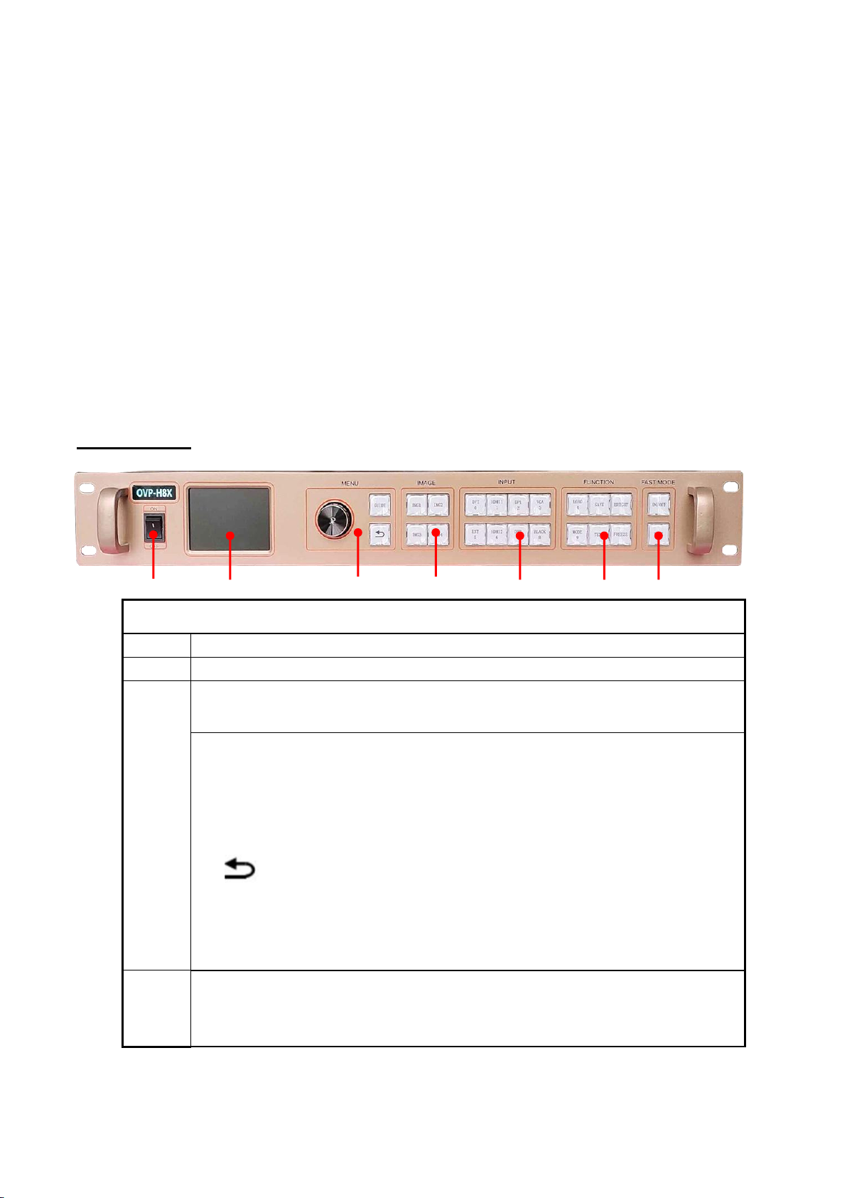
Panel instruction........................................................................................................................................................7
Front panel..........................................................................................................................................................7
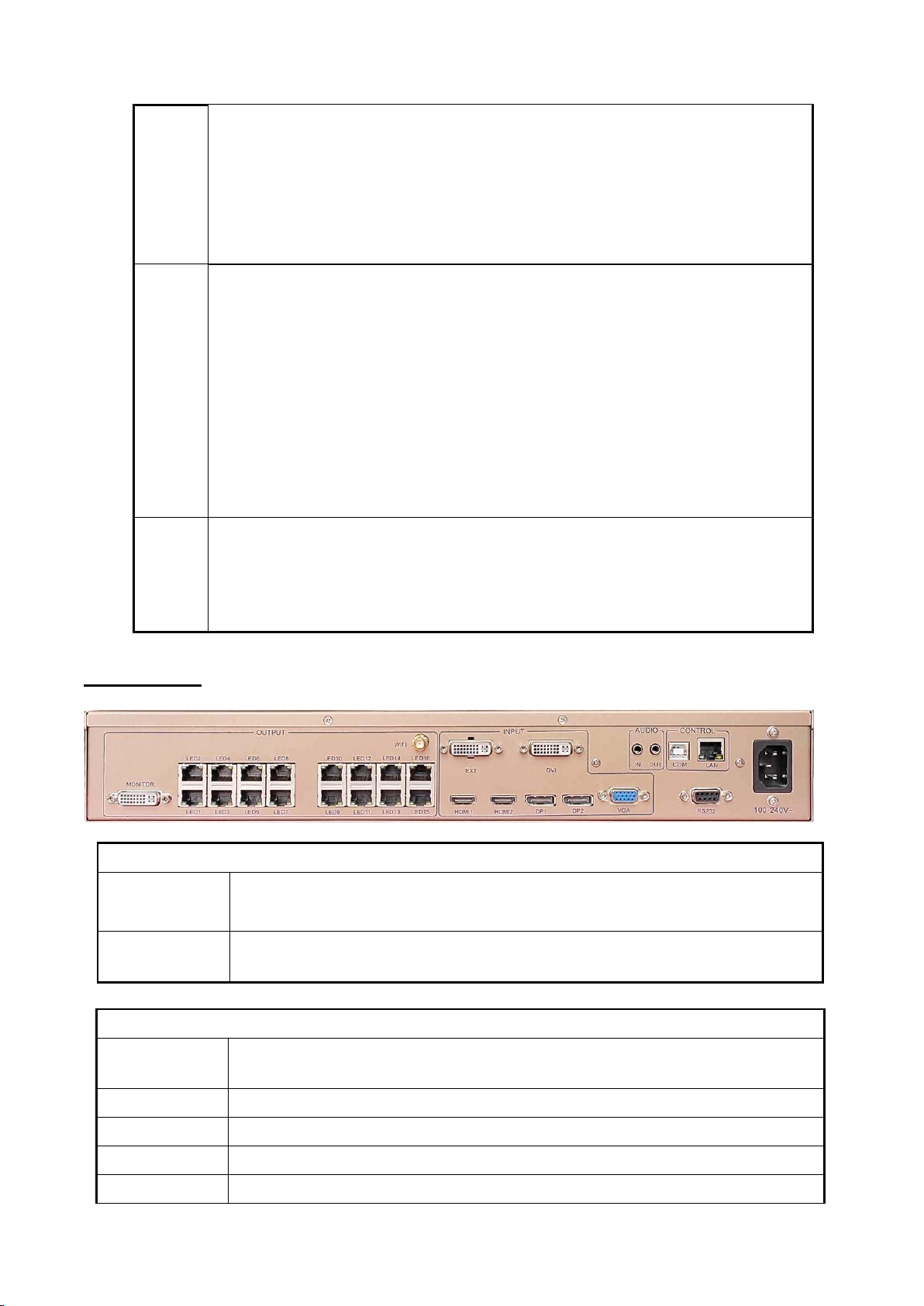
Back panel...........................................................................................................................................................8
Basic steps...................................................................................................................................................................9
Menu.............................................................................................................................................................................9
1.1 Menu key operation.........................................................................................................................................9
1.2 Initial menu status......................................................................................................................................... 10
Initial menu status.......................................................................................................................................... 10
Main menu........................................................................................................................................................11
Output configuration.....................................................................................................................................13
Image effect menu......................................................................................................................................... 14
Image capture menu......................................................................................................................................15
Note:................................................................................................................................................................... 16
(1) The image interception is for the input source, so the width and height of the interception
can not exceed the resolution of the currently intercepted source, and the interception will
not work if it exceeds it.................................................................................................................................16
(2) Through the panel input source selection shortcut keys, different input sources can be
selected to perform image interception..................................................................................................16
Advance............................................................................................................................................................. 16
User mode save and recall..................................................................................................................................... 3
User mode save.................................................................................................................................................3
User mode recall............................................................................................................................................... 3
Intelligent navigation...............................................................................................................................................4
FAQ................................................................................................................................................................................5
Specifications............................................................................................................................................................. 7

INSTRUCTION
Safety Notice
There are high voltages in this product, so non-maintenance personnel must not open
the case or repair the equipment by yourself to avoid danger.
The input voltage range of this product's AC power supply is 100 ~ 240V, 50 / 60Hz,
please use the correct power supply.
This product is grounded through the power cord. In order to avoid current impact,
please plug the power cord before connecting the product input or output port
Connect to a grounded socket.
Protective grounding of ground conductors in power cords is essential in safe operation.
Before proceeding with any hardware operation, please turn off the power of the LED video
processor and release your body by touching the grounded surface On the static electricity.
you want to disconnect or unplug any signal line or control line, please make sure that all
power cords have been unplugged in advance. Please use it in a clean, dry and ventilated
environment. Do not put this product in a high temperature and humidity environment.
This product is an electronic product. Please keep away from fire, water and flammable
and explosive dangerous goods. If you receive unusual noises such as strange noises, smoke
or odors, you should unplug the power plug immediately without contacting the dealer.

About software
Do not alter, decompile, disassemble, decrypt, or reverse engineer the software installed
on this product, all of which are far away.
FUNCTION
Description
OVP-H8X video controller is developed by our company for LED large screen display,
rented screen, conference room,High-end video processing equipment in the studio and
other markets. This product adopts the 4K image processing technology designed for
small-pitch LED display, which can effectively eliminate the edge jagged phenomenon
caused by the enlargement of the image and reduce the out-of-focus blur feeling after the
image is enlarged. OVP-H8X can receive ultra high-definition 4096x2160 @ 60Hz image
input and display four windows at the same time. The output of ultra-large resolution can
reach up to 4096x2160 @ 60Hz, 8192x1080 @ 60Hz, 16000x654 @ 60Hz, etc., which can
meet the application requirements of ultra-large LED display, hybrid LED display, and
special-shaped screen. At the same time, OVP-H8X also integrates 16 Gigabit Ethernet port
outputs, which combines the conventional video processor and the receiving card, which not
only improves the reliability, but also greatly facilitates the maintenance of the LED display.

Features
Single device can control 10.46 million pixels, horizontal maximum 16000 pixels, vertical
maximum 3840 pixels;
Integrated 16-channel Gigabit Ethernet port output interface;
Fast and seamless switching between all input signal sources and output modes;
With 7-channel ultra high definition (UHD) digital and analog input interfaces;
Equipped with DVI monitor output interface, support local picture output monitor;
Support 5 digital input ports DVI \ HDMI custom input resolution setting;
Support 2 channels 4K * 2K @ 60Hz and 2 channels 4K * 2K @ 30Hz input;
Support hot backup of input signal source;
16 user modes can be pre-stored for users to quickly call;
With fast switching mode, the pre-monitoring screen can be seamlessly switched to the
LED large screen for instant broadcast;
With "intelligent navigation" setting function, convenient for users to set up quickly;
The device can be controlled by panel keys, LAN, USB, WIFI, RS232.

Panel instruction
Front panel
Interfaces
1
Power supply
2
2.8”full color LCD screen(320×240)
3
Operate screen area and display the system status information through
the LCD.
MENU 区
Short press [OK]:means turn into menu or
confirm
[GUIDE] : fast switch to”smart
guiding”interface
[ ]: means exit the current operation
4
IMAGE
[IMG1]- [IMG4]:You can select the opened screen 1 ~ screen 4 window,
and the LED light indicates the currently selected window.
○
1
○
2
○
3
○
4
○
5
○
6
○
7

5
INPUT
The input Selection key area has [DVI] ~ [DP2] 8 buttons, 8 input source
port selection buttons, and correspond to the input interface logo of the
back panel.
When BLACK is pressed, the LED indicator of BALCK is on, and the screen
output is black.
6
FUNCTION
[LOAD]:fast switch to user mode
[SAVE]:fast switch to user save mode
[BRIGHT]:fast switch to brightness
adjust hot key.
[MODE] :fast switch to system fixed mode
menu.
[TEXT]:keep the function button
[FREEZE]:image freeze hot key
7
FAST-MODE
[ON/OFF] fast mode of ON/OFF hot key
[TAKE] fast switch from current LED screen signage to the fast switch signage
source
Back panel
Video output interface
LED1~LED16
16 nos of Gigabit network output ,connect with screen receiving card
MONITOR
Simultaneous multi-screen monitoring DVI output interface, connect to
LCD display
Video input source
EXT
Extended input port, default is DVI, HDMI or SDI or wireless screen input is
optional
DVI
DVI interface
HDMI1
HDMI 1
HDMI2
HDMI 2
DP1
DP 1

DP2
DP 2
VGA
VGA
Audio input/out put port
HDMI audio
HDMI video input port built-in
DP audio
DP video input port built-in
AUDIO_IN
Analog audio input port
AUDIO_OUT
Analog audio output port
Control interface
LAN
Network control port
COM
USB input port
WIFI
WIFI wireless control
RS232
RS232C control DB9 port
Power supply
Input voltage
100-240V~50/60Hz
Basic steps
Click [OK] to enter the main menu interface, and then follow the steps below :
Step 1: import or set the LED screen parameters;
Step 2: select the corresponding signal source according to the user's needs;
Step 3: Enter the "LED screen parameter \ display window adjustment" menu, adjust the picture
appropriately (change the aspect ratio or start bit);
Step 4: Turn to the panel "SAVE" button to enter the "user save mode " to save the current display
mode for the next call.
Note: For detailed instructions on the above four steps, please refer to the next chapter "Introduction
to Main Menu".
Menu
1.1 Menu key operation
The key operation area which includes a knob, a confirmation key [OK], a return key [ ] and a
[GUIDE] key.
In the initial state of the system, short press [OK] to enter the main menu setting interface. When
pressing the return key, the menu system will return to the previous menu until it returns to the

initial state.
In the browsing state, turn [Knob] counterclockwise to move the cursor upward or left; turn [Knob]
clockwise to move the cursor downward or right. When moving the cursor to the item to be
adjusted, press the [OK] key to enter the corresponding setting submenu. At this time, turn the
[knob] counterclockwise to decrease the current parameter value; turn the [knob] clockwise The
current parameter value can be increased. AdjustWhen finished, short press【OK】key to write data
to save. To return to the previous menu, use the return key; until you return to the initial state.
press[GUIDE] key can quickly switch out the "intelligent navigation" setting interface.
Note: The [knob] cannot be turned too fast, otherwise the value adjustment will change very little
and should be rotated at a constant speed.
1.2 Initial menu status
During the system startup, the LCD screen will display the startup interface. After the startup is
complete, the current machine status will be displayed on the screen. The initial menu of the system
startup is shown in the following figure:
Initial menu status
During the system startup, the LCD screen will display the startup interface. After the startup is
complete, the current machine status will be displayed on the screen. The initial menu of the system
startup is shown in the following figure:
Above three area display content instruction:
Input:
It displays the input source selection information, including the input source signal
format detected by the system.
output:
The first line: display the actual LED screen size set by the user
The second line: display the prompt information
Upper right corner:
The current contrast, brightness value and key lock status are displayed.

Main menu
The device uses a 2.8-inch LCD display software menu, the LCD display pixel is 320 * 240, and the
font 24 * 24 can display 10 lines. The user operation menu is divided into six categories. Click [OK] in
the non-menu state to pop up the main menu:
Main menu
Level 2 and Level 3 submenus
Output setup
LED screen size (horizontal width, vertical height)
Network port output settings (network port LED1-LED16: horizontal width,
vertical height, horizontal start, vertical start)
Window
layout
Window 1 (horizontal width, vertical height, horizontal start,
vertical start) is always on.
Window 2 (picture switch, horizontal width, vertical height,
horizontal start, vertical start)
Window 3 (picture switch, horizontal width, vertical height,
horizontal start, vertical start)
Window 4 (picture switch, horizontal width, vertical start)
Height, horizontal start, vertical start)
Image effect
Brightness, contrast, saturation, sharpness, color temperature, dynamic
contrast
Image capture
Intercept switch, intercept width, intercept height, horizontal start, vertical
start
Mode save
Mode1- mode16

Advance
Input resolution (horizontal width, vertical height, refresh rate)
Input hot backup VGA settings (automatic adjustment, horizontal start,
vertical start)
Timed switching (task 1, task 2, ...)
Other settings (image rotation, sound settings, screen projection equipment)
Test chart (closed, Figure 1 to Figure 8) Key lock (open, closed)
Factory setting (VGA ADC calibration, VGA DDC programming, comment,
factory reset, firmware version)

Output configuration
In the non-menu state, click the [OK] button to enter the main menu, and then select "Output
Settings", the following menu will pop up:
1. LED screen size
In the non-menu state, click [OK] to enter the main menu, then select "Output Settings", and
then select "LED Screen Size" to enter the LED screen size menu:
Note
:
After the PC screen control software is used to complete the settings of the “connect receiving
card” of each network port of the LED screen, the size of the LED screen is automatically calculated
and updated to the controller synchronously, so it is generally not necessary to set the LED screen
parameters (including LED The screen size and the network port parameters);
If you have previously set up an archive, you can complete the "LED screen parameter" data
synchronization through the PC control software "import \ export configuration";
The width and height of each network port must be the same as the local size of the LED screen
covered by the interface card actually carried by each network port. By changing the starting position
of each network port, the LED screen can be arbitrarily spliced (each Gigabit of the network port can
display any part of the screen or repeat it);
Pay attention to the size range of the LED screen and the total load points of the LED screen:
LED screen horizontal width <= 16000
Vertical height of LED screen <= 3840
LED screen horizontal width x LED screen vertical height <= 10464000 (when width> height)
LED screen horizontal width x LED screen vertical height <= 10430000 (when width <height)

2. LAN output setup
In the non-menu state, click [OK] to enter the main menu, then select "Output Settings", and
then select "Network Port Output Settings" to enter the network port output settings menu:
Note:
(1)As mentioned above, when the PC screen control software completes the settings of the
“connect card access” of each network port of the LED screen, it will automatically calculate the
LED screen size and update it to the controller synchronously. Parameters (including LED screen
size and network port parameters);
(2)When you need to "arbitrarily splice" or set for each network port, please pay attention to the
range and load points of a single network port:Horizontal width: 256 ~ 4000 Vertical height: 128
~ 3840Horizontal width x vertical height <= 655360 (when width> height)Horizontal width x
vertical height <= 652738 (when width <height)
(3) Network port 1, network port 2, network port 9, network port 10 support audio output, and
support mutual backup between network ports.
Image effect menu
In the non-menu state, click the [OK] button to enter the main menu, and then select "Image
Effect" to enter the image effect menu.

Brightness: The adjustment range is 0-100, and the default value is 50.
Contrast: the adjusting range is 0-100, and the default value is 50.
Saturation: the adjustment range is 0-100, and the default value is 50.
Sharpness: the adjustment range is 0-10, and the default value is 5.
Dynamic contrast: the adjustment range is 0-4, and the default value is 1. 0 is off, which is
not applicable to the input VGA signal source.
Color temperature type: "Warm", "Natural", "Poor" and "Custom" are divided into four
options.
Customized color temperature: red adjustment range 0-100.
The blue adjustment range is 0-100.
The green adjustment range is 0-100.
Note: The “BRIGHT” shortcut key on the panel can also immediately switch out the above menu
to perform “Brightness” adjustment.
Image capture menu
In the non-menu state, click the [OK] button to enter the main menu, then select "Image
Capture" to enter the image capture menu:

Capture switch: The input image intercept function is on or off, and the default is off.
Capture width: the minimum value is 128, and the maximum value is "the width of the
input signal".
Capture height: The minimum value is 128, and the maximum value is "the height of the
input signal".
Horizontal start: The minimum value is 0, and the maximum value is the difference
between "input signal width" minus "capture width".
Vertical start: The minimum value is 0, and the maximum value is the difference between
"the height of the input signal" minus the " capture height".
Note:
(1) The image interception is for the input source, so the width and height of the
interception can not exceed the resolution of the currently intercepted source, and the
interception will not work if it exceeds it.
(2) Through the panel input source selection shortcut keys, different input sources can be
selected to perform image interception.
Advance
In the non-menu state, click the [OK] button to enter the main menu, and then select
"Advanced " to enter the advanced options menu:
1. Input resolution

The input resolution setting provides users with DVI / HDMI input signal source EDID
editing function, and sets the recommended resolution of the input signal source. The
WIN7 computer graphics card can automatically read the recommended EDID resolution of
the input DVI / HDMI port of the device. Output recommended resolution; after WIN10
input resolution setting is completed, you must manually select "Recommended
Resolution" on the computer.
By setting the input resolution, users can realize the input and output point-to-point
display of the ultra-high-resolution LED large screen within the range of 3840x2160. The
point-to-point display does not scale the input image, so the display image on the LED
large screen can reach the highest definition degree.
Select the input resolution in the "Advanced Options" to enter the input resolution menu:
Horizontal width: adjustment range 640-3840
Vertical height: adjustment range 480-2160
Refresh rate: adjustment range 30 or 60
Note:
The actual adjustment range is not related to the interface type and the input bandwidth
limitation. For this device, because the standard used by the system's input source DP is
DP1.2, it can reach the highest 4K level input resolution: 3840x2160 @ 60Hz; HDMI uses the
standard It is HDMI1.4, so it can reach the highest 4K input resolution: 3840x2160 @ 30Hz.
2. Input hot backup
Different hot backup sources can be selected for the four display screens. Once the
current playback source of a certain screen is lost, the system will automatically switch to the
backup source.

3. VGA setup
Select VGA setting in "Advanced Options", then enter the VGA setting menu:
Horizontal start: adjustment range 0-300.
Vertical start: the adjustment range is 0-300.
Note:
(1)The actual adjustable range of horizontal start and vertical start is determined by the
internal calculation of the system.
(2) Under normal circumstances, when the VGA input image screen is shifted, the screen
position can be corrected by several automatic adjustments. If the automatic adjustment is
invalid, then use the manual adjustment of the "horizontal start" and "vertical start" positions
on the screen.
(3) The VGA screen is dark, just execute the "ADC correction". Generally, it will be corrected
before leaving the factory.
4. Timing switch
In the "Advanced Options", select the timer switch, then enter the timer switch setting
menu:
Notice:
(1) The user must first calibrate the internal clock of the system before using the timing
switch function. Calibration is done by the PC software.
(2)When the timing switch is turned on, several tasks can be set, and different user modes
can be called in different time periods (this user mode must be saved in advance), and the

www.onbonbx.com 第 2页
task settings are also completed by the PC software;(
(3) When the timing switch is turned on and the task is valid, the timing switch can be turned
off or on at any time through the LCD menu.
5. Other setup
There are three adjustment items in "Other Settings":
Image rotation: contains three special effects of "HV mirror", "horizontal mirror" and
"vertical mirror", the default is "off".
Sound setting: including audio switch and volume setting.
Screen projection device: Use electronic devices that support Android system or Apple
system to perform screen projection display.
6. Test picture
It can provide 8 kinds of test images in the system: Figure 1 ~ Figure 8, the default is
"off".
7. Key lock
The default is "off". When the "key lock" is in the on state, except the [OK] key, pressing
other keys will not work.
8. Factory setup
Select the factory settings in the "Advanced Options" to enter the factory settings menu:
VGA ADC calibration: It is used to calibrate the VGA input source. It is usually
performed before leaving the factory.
VGA DDC programming: When the input source is VGA, if the output
resolution of the computer cannot be changed, you need to do the
programming action here.
Language: Provide two choices of "Chinese" and "ENG", the default is Chinese.

www.onbonbx.com 第 3页
Factory reset: Reset to factory default.
Firmware version: Used to query the current software and hardware version
number, and the factory date.
User mode save and recall
User mode save
Press the front panel shortcut "SAVE" to quickly switch out the user mode save menu:
After selecting the save mode, press [OK] to save.
Note:
(1)The solid circle before the mode indicates that the currently selected mode data already
exists, and the open circle indicates that the currently selected mode data does not exist.
(2)Up to 16 user modes can be saved. In addition to the size, position and status of the
screen, the parameters saved in the user mode include brightness and contrast.
(3) When the splicing method is changed, the saved user mode will be cleared.
User mode recall
Press the front panel shortcut "LOAD" to quickly switch out the user mode to call the
menu:
Note:
Only user modes that have been previously saved can be called;
(2) For the saved user mode, you can also press "MODE" first, then directly press numeric
Table of contents
Other Onbon Media Converter manuals
Popular Media Converter manuals by other brands

Okto Research
Okto Research DAC8 PRO owner's manual

Teryair
Teryair SN 16 PG Operation & maintenance guide

Baumer
Baumer HOG 16 Mounting and operating instructions

CEL-MAR
CEL-MAR ADA-7210 user manual

Extron electronics
Extron electronics mediaport 200 user guide

N-audio
N-audio Isolated Guitar Splitter / DI Box manual