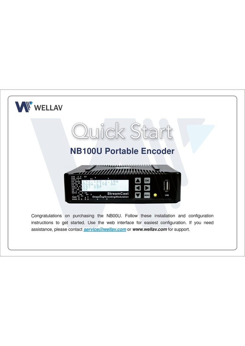
Wellav UMH252 User manual

MPEG-4/H.264 SD/HD Encoder
User manual
V1.13-N

1
TABLE OF CONTENT
SAFETY INSTRUCTION.................................................................................... 2
ABOUT THIS MANUAL..................................................................................... 4
ACCESSORIES LIST ........................................................................................ 5
1 OVERVIEW..................................................................................................... 6
1.1 PRODUCT INTRODUCTION ...........................................................................................6
1.2 FUNCTION &FEATURES ..............................................................................................6
1.3 FRONT PANEL..............................................................................................................7
1.4 REAR PANEL................................................................................................................8
2 OPERATING INSTRUCTION.......................................................................... 9
2.1 START UP.....................................................................................................................9
2.2 HIERARCHICAL MENU ..................................................................................................9
2. 3MENU FLOW RULES ..................................................................................................12
2. 4OPERATION OF FRONT PANEL..................................................................................13
2.4.1 Encode Setup.................................................................................... 13
2.4.2 TS/IP Setup....................................................................................... 14
2.4.3 System.............................................................................................. 16
2.5 NETWORK MANAGEMENT OPERATION .......................................................................17
2.5.1 Overview........................................................................................... 17
2.5.2 Software installation.......................................................................... 17
2.5.3 Login interface................................................................................... 18
2.5.4 Operation interface............................................................................ 19
2.5.4.1 Encoder..............................................................................................................................19
2.5.4.2 Ethernet..............................................................................................................................21
2.5.4.3 System ...............................................................................................................................22
2.5.4.4 Upgrade..............................................................................................................................23
3 TROUBLE SHOOTINGS............................................................................... 25
4 SPECIFICATIONS......................................................................................... 27
4.1 PHYSICAL SPECIFICATIONS.......................................................................................27
4.2 INPUT SPECIFICATIONS .............................................................................................27
4.3 OUTPUT SPECIFICATIONS .........................................................................................27
4.4 SIGNAL SPECIFICATIONS...........................................................................................28
5 MAINTENANCE AND SERVICES................................................................ 29

2
Safety Instruction
The following are the important safety instructions that you need to know before
operating this equipment. Please read and understand these notices before
using the equipment.
The operation and maintenance of this equipment must be handled by
professionals.
The equipment should be kept in a shady and cool place. Do not expose it
to high temperature or sunlight.
Please use the cable of good quality and make sure the connector is in
good condition.
Please do not use the power supply that doesn’t match the requirement.
Please do not open the machine cover.
Keep 10mm space for ventilating.
Keep the operating temperature within 0℃~40℃and the humidity within
10%~90% for long life-span.
Please do not operate the machine in a humid condition.
Please unplug the power supply cable under the following circumstances:
The power supply cable or the socket is damaged
Any liquid has been spilled into this equipment
The equipment has been collided or the components are damaged
Unplug the equipment from wall outlet before cleaning. Please use dry cloth
for cleaning.
The apparatus shall be connected the mains socket outlet with a protective
earthing connection.
The appliance coupler used as the disconnect device shall remain readily
operable.
This product has gone through regulated EMC test and meets with EMC
safety requirement.
(Note: Such tests are conducted in a controlled EMC environment. A controlled EMC
environment exists in a building where the installation has been designed having special
regards to EMC, and where technical personnel are present with experience of EMC
technology.)
Do not use this apparatus near water –The appliance should not be used
near water or moisture –for example, in a wet basement or near a
swimming pool, and the like.

3
Correct Disposal of this product. This marking indicates that this
product should not be disposed with other household wastes throughout the
EU. To prevent possible harm to the environment or human health from
uncontrolled waste disposal, recycle it responsibly to promote the
sustainable reuse of material resources. To return your used device, please
use the return and collection systems or contact the retailer where the
product was purchased. They can take this product for environmental safe
recycling.

4
About this manual
This manual introduces the basic conception of this MPEG-4/H.264 HD/SD
Encoder, including the detailed description of installation, setup and operating
method. Please read this manual carefully, especially the ‘Notice’ in the black
frame, to insure the correct operation.
Attention:
Please use the cable with good quality and confirm the connecter is in
good condition.
Please make sure the power source is qualified and do not use the power
line without the earth wire.
Please do not open the device cover privately

5
Accessories List
Item
Description
Quantity
1
Encoder Main Unit
1
2
Power Cord
1
3
NMS & User Guide Disc
1
4
RCACable (Optional)
1
5
BNC Cable (Optional)
1
6
HDMI Cable (Optional)
1

6
1 Overview
1.1 Product introduction
This new generation of MPEG-4/H.264 SD/HD Encoder supports HDMI, HD/SD
SDI, YPbPr, CVBS, SPDIF input and ASI and IP output. With improved algorithm
and compression efficiency, it presents major improvements in picture quality,
offering crisp and vibrant video at extremely low bit-rates. It helps deliver more
SD/HD video and audio channels in the available bandwidth, enabling the
launch of additional SD/HD service in an existing digital video or an IPTV
network.
1.2 Function & Features
Compatible with MPEG-4/H.264-AVC standard
MPEG-1 LayerⅡaudio encoding
SD video input format: NTSC/PAL
HD video input format: SMPTE-296/SMPTE-274
Support HDMI, SD/HD SDI, YPbPr and CVBS input
Digital SPDIF audio input
Support multiplexing of MPEG-4 video and audio compressed data stream
with DVB packets
SI related table editing
Support SD or HD TS stream output with the corresponding definition of
input signal
Two identical ASI outputs
IP output compliant with UDP/RTP protocol (optional)
Convenient and simple NMS for long-range management of the equipment

7
1.3 Front Panel
1. Power indicator: when you connect the power cord and start the equipment,
this indicator will be light all the time.
2. Lock indicator: when the output stream is stable, this indicator will be light
all the time.
3. Alarm: if there’s any abnormity (e.g. there’s no input stream or output
stream.), this indicator will be light all the time.
Notice: when you switch options in the ‘Encode Setup’ menu, both ‘Power’ and
‘Lock’ indicators will go out within several seconds, and it’s the normal
phenomena.
4. LCD Screen: display content of the menu you are operating.
5. Direction Keys: switch different options in each menu via the four keys.
6. MENU: enter the main menu, cancel the modification or exit from any menu.
7. OK: enter submenus or confirm the modification of the parameters.
7
1
2
3
4
5
6
7

8
1.4 Rear Panel
1. ETHERNET: connect this port to your server to realize the remote
management.
2. TS OUT: output the encoded stream as IP format.
3. ASI1 OUT: output the encoded stream as TS format.
4. ASI2 OUT: this output is just the same as ASI1 OUT.
5. HD-SDI IN: it supports both SD and HD SDI stream input with BNC interface.
6. HDMI IN: to encode the HD program, connect the HDMI cable to the port.
7. YPbPr: component YPbPr input.
8. A/V: video with CVBS format and audio input.
9/10. AC-3 Audio IN: the four ports with ‘FL’ and ‘FR’ together are used to input
the Dolby digital AC-3 audio.
11. SPDIF IN: digital audio input with optical interface.
12. Information: PowerAC, Max Power Consumption and CAUTION.
13. Grounding: the equipment should be earthed by connecting the ground
wire.
14. SWITCH: turn ON or OFF the equipment.
15. POWER: connect the equipment and power supply with the power cord.
16. Power Specifications: AC 90~250V, 50/60 Hz. (Note: Inrush Current at initial
switch on: 1.55A. Inrush Current after power supply interruption: 2.3A)
Notice: the function of ‘AC-3 IN’ and ‘SPDIF IN’ is not available temporarily;
they’re reserved for future use.
1
2
3
4
5
6
7
8
9
10
11
12
13
14
15
16

9
2 Operating instruction
Please make sure that all input/output cables are connected well. The
parameters can be configured by the operation of buttons through the guide of
menu displayed on LCD screen.
2.1 Start up
Start up the encoder, after about 8 seconds, the LCD displays initial state:
After start up, the encoder starts to encode automatically, LCD displays as
follows:
It includes the type and IP address of this equipment.
2.2 Hierarchical menu
Operation menu is a multilevel menu. The first level is initial interface. Each
menu item could have its own submenu. In the same way, each submenu item
can have its own submenu too. Due to the limitation of word count displayed, it
only can display one menu item at one time. Each menu item can display two
lines of content: the first line is the name of menu item; the forepart of second
line is the present value of adjustable parameter. The parameter can be
modified in the process of encoding.
HD/SD Encoder
IP: 192.168.1.16
HD/SD Encoder
[V 1.0.0] booting……

10
Menu Structure
CLASS1
CLASS
2
CLASS3
CLASS4 (or Options)
DEFAULT
PARAMETER
Main
Menu
Encode
Setup
Input Source
CVBS, HDMI, YPbPr,
SDI
CVBS
Parameter Setup
Video Encode Rate
10000
Audio Encode Rate
(32/64/128/192/256/3
20/384 Kbps)
256K
Video PID
4113
Audio PID
4352
PCR PID
4097
PMT PID
4096
Program Number
1
Transport Stream ID
0
Program Name
Program-1
Provider Name
Encoder
Gop Struct
(IBP/IBBP)
IBBP
Encode Mode
(CBR/VBR)
CBR
Max Encoder
(Biterate)
6000
Min Encoder
(Biterate)
0
Frame Rate
(59.94I/60I)
60I
TSIP
Setup
IP Source
Address
192.168.1.122

11
UDP Source Port
>1024
1000
Enable Channel
Enable, Disable
Enable
Packet Size
188, 204
188
TS Packets per
RTP
1-7
7
Type of Service
Normal, Min Delay,
Max Throughput
Max Reliabiability
Monetary Cost
Normal
Protocol
UDP, RTP
UDP
Time to Live
1-255
8
UDP Destination
Port
>1024
1234
IP Dest Address
224.1.0.0 ~
238.255.255.255
227.10.20.30
Source MAC
Address
01:02:03:04:05:
06
System
Local Setup
Host IP Address
192.168.1.16
Host Gateway
192.168.1.1
Host Subnet Mask
255.255.255.0
Host MAC Address
A0:07:ED:0F:60
:1F
Lock Timeout Setup
(Lock Now/5 Min/3
Min
/2 Min)
2 Min
PIN Setup
1234
Security Mode
(Security Mode)
Standard Mode

12
Host Trap IP Address
0.0.0.0
Language Select
English, Chinese
English
Factory Setting
NO, YES
NO
Version
Information
Hardware Version
The current
version
Software Version
The current
version
2. 3 Menu flow rules
1. Due to the limitation of word count displayed, it is impossible to display all
menu items in the same level. Menu items in the same level can be switched
through the two buttons ‘↑↓’.
2. The parameter only can be modified in the end level menu. Press button ‘OK’
to entry the lower level menu when it chooses a non-end level menu.
3. There is more than one way to enter the lower level menu from the higher
level menu.
4. Enter the end level menu, and modify the parameter and press ‘OK’ to save it.
If it has no use for modifying the parameter value, press ‘MENU’ to return the
next higher level menu and keep the former parameter value, or press ‘OK’ to
confirm the former one.
5. During the process of encoding, LCD will return the initial interface
automatically if any button operation stays on a menu item over 5 minutes.
Notice: to modify any parameter and save it, you need press ‘OK’ to enter
the editing status firstly, and then press ‘↑→↓←’ to select other options or
input the parameter. Lastly, press ‘OK’ to save the new parameter.

13
2. 4 Operation of Front Panel
2.4.1 Encode Setup
●Input Source
▲The options includes: CVBS (A/V), HDMI, SDI and YPbPr, and you should
select the right Input Source according to your application.
● Video Encode Rate ● Audio Encode Rate
★Input the Video Encode Rate value and select the Audio Encode Rate
according to your request.
Notice: the larger you input/select the Video/Audio Encode Rate is, the
broader bandwidth the program takes up.
●Video PID ● Audio PID
●PCR PID ● PMT PID
★The range of each PID value is: 0 ~ 8192, you can input any value within this
range according to your arrangement. However, be sure to set different PID for
Video, Audio, PCR and PMT.
●Program Number ● Transport Stream ID
Video Encode Rate
10000
Input Source
CVBS
Video PID
4113
Audio PID
4352
PCR PID
4097
PMT PID
4096
Program Number
1
Transport Stream ID
0
Audio Encode Rate
256K
The range is 1000 ~ 20000 Kbps
Options: 32/64/128/192//256/320/384 Kbps

14
●Program Name ● Provider Name
★Input the information about the encoded program, including Program
Number, Program Name, Transport Stream ID and Provider Name.
Tips: the Transport Stream ID is set for knowing this stream from other streams
within the same broadcasting network.
● Frame Rate ● Min Encode Rate
According to the signal select frame rate as 60I or 59.94I
● Max Encode Rate ● Encode Mode
Option: CBR/VBR
● GOP Struct
Option: IBBP/IBP
2.4.2 TS/IP Setup
● Enable Channel ● Packet Size
Program Name
Program-1
Provider Name
Encoder
Enable Channel
Enable
Packet Size
188
Open or close the output channel by
select Enable or Disable.
Select the TS packet size:
188 or 204 Byte
Frame Rate
60I
Min Encode Rate
0
Max Encode Rate
15000
Encode Mode
CBR
GOP Struct
IBBP

15
Source MAC Address
01:02:03:04:05:06
● TS Packets per RTP ● Protocol
● UDP Destination Port ● IP Dest Address
Notice: it’s necessary to set different ‘IP Dest Address’ or ‘UDP Destination
Port’ for each equipment when more than two equipments work as IP
output mode within the same broadcasting network.
● Type of Service ● Time to Live
▲When the equipment transmits the IP stream to other broadcasting network
by connecting TSIP port to the Router, the two parameters work. If you know
little about them, keep them in default.
● IP Source Address ● UDP Source Port
● Source MAC Address
TS Packets per RTP
7
Protocol
UDP
UDP Destination Port
1234
IP Source Address
192.168.1.122
UDP Source Port
1000
IP Dest Address
227.10.20.30
Type of Service
Normal
Time to Live
8
Select the amount of TS packets in
each RTP packet. The range is 1-7.
Select the transmission format:
UDP or RTP.
Set the port for broadcasting the IP stream,
it should be larger than 1024.
Set the address for broadcasting the
IP stream, the range is:
224.1.0.0~238.255.255.255
★The three parameters are used in
the internal communication of the
equipment, so you needn’t modify
them for normal application.

16
2.4.3 System
●Host IPAddress ●Host Gateway
●Host Subnet Mask ●Host MAC Address
▲The four parameters are set for the connection between equipment and its
NMS running on your server.
●Lock Timeout Setup ●PIN Setup
Used to set the time when front panel
LCD will be locked.
Option: 2Min,3Min,5Min,Lock Now
Host IP Address
192.168.1.16
Host Gateway
192.168.1.1
Host Subnet Mask
255.255.255.0
Host MAC Address
A0: 07: ED: 0F: 60: 1F
Notice:
1. After you modify the four parameters and press MENU button to apply
it, the equipment will restart automatically.
2. The ‘Host IP Address’ and the server’s IP address, should be in the
same network section; ‘Host Gateway’ and the server’s gateway, ‘Host
Subnet Mask’ and the server’s Subnet Mask should be the same. For
example:
Parameter
Encoder
Server
IPAddress
192.168.1.x (x: 3 ~254)
192.168.1.2
Gateway
192.168.1.1
192.168.1.1
Subnet Mask
255.255.255.0
255.255.255.0
3. When more than two pieces of encoders are connected to the same
server, it’s necessary to set different ‘Host IP Address’ and ‘Host MAC
Address’ for each one.
Lock Timeout Setup
2 Min
PIN Setup
****
1234 in default

17
●Security Mode
Option: Standard Mode/Security Mode
● Language Select
▲If needed, you can change the menu language into Chinese or English.
● Factory Setting
★You can set all the parameters back to the factory setting. If you select ‘YES’,
it’ll display as the right picture and restart automatically.
●Hardware Version ●Software Version
★Press OK button on the front panel to query the current Hardware and Software
version about the equipment.
2.5 Network management operation
2.5.1 Overview
The network management software is a remote management program based
on web service, which can conduct a remote management on any computer
running on windows98 system or above.
2.5.2 Software installation
With the network management software recorded on it, a CD is sent along with
the machine. Put the CD into the disk driver and a compressed file package will
Language Select
English
Factory Setting
NO
Version Information
Software Version
Factory Setting
Restart …
YES
Version Information
Hardware Version
Security Mode
Standard Mode
Host Trap IP Address
0.0.0.0

18
show up, and then double click the file. Install decompression software first if
there isn't one. After decompression, double click MNG_V1.0.0.exe to open the
program and conduct a remote control.
2.5.3 Login interface
Double click MNG_V 1.0.0.exe, the login interface is like Fig 2-1, and then input
the User and Password, both of them are ‘admin’ in default. Enter ‘Login’ to go
to the interface like Fig 2-2.
Fig 2-1

19
Fig 2-2
It’s convenient to manage several equipments at the same time via the NMS.
The NMS will read and display the name and IP address of all the equipments
connected to the server automatically. Double click the equipment’s name to
enter the corresponding operation interface.
2.5.4 Operation interface
The operation interface is like Fig 2-3, there’re four pages used to configure the
equipment, including: Encoder, Ethernet, System and Upgrade. You’ll see the
‘Encoder’ page as soon as entering this interface.
2.5.4.1 Encoder
You can set the basic parameters about encoding program here.
●Video Source: Select the corresponding option according to the actual input
source, including: CVBS (A/V), HDMI, SDI and YPbPr.
●Video PID: The range PID value is: 1024 ~ 8175, you can input any value
within this range according to your arrangement. However, be sure to set
different PID for Video,Audio, PCR and PMT.
●Audio Source: Select the corresponding option according to the actual
input source, including: CVBS (A/V), HDMI, SDI and YPbPr.
The name and IP address of all the
equipments connected to the server.
Display the correlative information
about the equipment you’re operating.
Display the status of
equipments, including
connection and signal
locking status and so on.
These options are not
valid temporary.
Modify the user name
and password here.
Table of contents
Other Wellav Media Converter manuals

Wellav
Wellav DMP900 User manual

Wellav
Wellav NB100U User manual

Wellav
Wellav CMP201 User manual

Wellav
Wellav UMH160R User manual

Wellav
Wellav NB100 User manual

Wellav
Wellav NB100U User manual

Wellav
Wellav CMP100 User manual

Wellav
Wellav SMP181-HLS User manual

Wellav
Wellav UMH160UIG User manual

Wellav
Wellav UMH-150 User manual