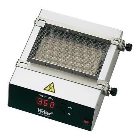
Weller WHP 3000 User manual

WHP 3000
Betriebsanleitung - Mode d’emploi - Gebruiksaanwijzing - Istruzioni per l’uso - Operating
Instructions - Instruktionsbok - Manual de uso - Betjeningsvejledning - Manual do utilizador -
Käyttöohjeet - √‰ËÁ›Â˜ §ÂÈÙÔ˘ÚÁ›·˜ - Kullan∂m k∂lavuzu -
Návod k pouÏití - Instrukcja obs∏ugi -
Üzemeltetési utasítás - Návod na pouÏívanie - Navodila za uporabo - Kasutusjuhend -
Naudojimo instrukcija - Lieto‰anas instrukcija -
Ръководство за работа
- Manual de exploatare
Naputak za rukovanje
200 / 600 W
600 / 1200 W
www. .com information@itm.com1.800.561.8187

D
F
NL
I
GBGB
FIN
P
DK
E
SGR
TR
CZ
PL
H
SK
SLO
EST
LT
LV
USA
CN
IL
RO
HR BG
D
F
NL
I
GB
FIN
P
DK
E
SGR
TR
CZ
PL
H
SK
SLO
EST
LT
LV
USA
CN
IL
RO
HR BG
D
F
NL
I
GB
FIN
P
DK
E
SGR
TR
CZ
PL
H
SK
SLO
EST
LT
LV
USA
CN
IL
RO
HR BG
D
F
NLNL
I
GB
FIN
P
DK
E
SGR
TR
CZ
PL
H
SK
SLO
EST
LT
LV
USA
CN
IL
RO
HR BG
D
F
NL
I
GB
FIN
P
DK
E
SGR
TR
CZ
PL
H
SK
SLO
EST
LT
LV
USA
CN
IL
RO
HR BG
D
F
NL
I
GB
FIN
P
DK
E
SGR
TR
CZ
PL
H
SK
SLO
EST
LT
LV
USA
CN
IL
RO
HR BG
D
F
NL
I
GB
FIN
P
DK
E
SGR
TR
CZ
PL
H
SK
SLO
EST
LT
LV
USA
CN
IL
RO
HR BG
D
F
NL
I
GB
FIN
P
DKDK
E
SGR
TR
CZ
PL
H
SK
SLO
EST
LT
LV
USA
CN
IL
RO
HR BG
D
F
NL
I
GB
FIN
P
DK
E
SGR
TR
CZ
PL
H
SK
SLO
EST
LT
LV
USA
CN
IL
RO
HR BG
D
F
NL
I
GB
FINFIN
P
DK
E
SGR
TR
CZ
PL
H
SK
SLO
EST
LT
LV
USA
CN
IL
RO
HR BG
D
F
NL
I
GB
FIN
P
DK
E
S
GRGR
TR
CZ
PL
H
SK
SLO
EST
LT
LV
USA
CN
IL
RO
HR BG
D
F
NL
I
GB
FIN
P
DK
E
SGR
TRTR
CZ
PL
H
SK
SLO
EST
LT
LV
USA
CN
IL
RO
HR BG
Inhaltsverzeichnis Seite
1. Achtung! 1
2. Beschreibung Technische Daten 1
3. Inbetriebnahme 1
4. Betrieb mit externem Sensor 2
5. Fehleranzeige im Display (4) 2
6. Weitere “Power On” Routinen 2
7. Zubehör 3
8. Lieferumfang 3
Table des matières Page
1. Attention! 4
2. Description Caractéristiques techniques 4
3. Mise en service 4
4. Fonctionnement avec capteur externe 5
5. Affichages d’erreurs sur l’écran de visualisation (4) 6
6. Autres fonctions “Power On” 6
7. Accessoires 6
8. Étendue de livraison 6
Inhoudsopgave Pagina
1. Opgelet! 7
2. Beschrijving Technische gegevens 7
3. Ingebruikneming 7
4. Gebruik met externe sensor 8
5. Foutmeldingen op het display (4) 8
6. Verdere “Power On” routines 8
7. Accessoires 8
8. Levering 8
Indice Pagina
1. Attenzione! 9
2. Descrizione Dati tecnici 9
3. Messa in funzione 9
4. Funzionamento con sensore esterno 10
5. Messaggi d’errore sul display (4) 10
6. Altre routine di accensione (Power On) 10
7. Accessori 11
8. Materiale in dotazione 11
Table of contents Page
1. Attention! 12
2. Description Technical data 12
3. Placing in operation 12
4. Operation with external sensor 13
5. Error indications on the display (4) 13
6. Other “Power On” routines 13
7. Accessories 13
8. Items supplied 13
Innehållsförteckning Sida
1. Observera! 14
2. Beskrivning Tekniska data 14
3. Idrifttagning 14
4. Drift med extern sensor 15
5. Felvisningar i display (4) 15
6. Ytterligare “Power On” rutiner 15
7. Tillbehör 15
8. Leveransomfattning 15
Índice Página
1. Atención! 16
2. Descripción Datos técnicos 16
3. Puesta en marcha 16
4. Funcionamiento con el sensor externo 17
5. Indicación de fallos en la pantalla de visualización (4) 18
6. Otras Power “On Routine” 18
7. Accesorios 18
8. Volumen de suministro 18
Indholdsfortegnelse Side
1. Bemærk! 19
2. Beskrivelse Tekniske data 19
3. Ibrugtagning 19
4. Drift med ekstern sensor 20
5. Fejlvisning på displayet (4) 20
6. Yderligere “Power On” rutiner 20
7. Tilbehør 20
8. Leveringsomfang 20
Índice Página
1. Atenção! 21
2. Descrição Dados técnicos 21
3. Colocação em serviço 21
4. Funcionamento com sensor externo 22
5. Indicação de erro no mostrador (4) 22
6. Outras rotinas de activação 22
7. Acessórios 23
8. Equipamento a fornecer 23
Sisällysluettelo Sivu
1. Huomio! 24
2. Tuoteseloste Tekniset tiedot 24
3. Käyttöönotto 24
4. Käyttö erillistä lämpötunnistinta hyödyntäen 25
5. Vikanäytöt - display(4) 25
6. Muut power on -rutiinit 25
7. Lisävarusteet 25
8. Toimituksen sisältö 25
¶›Ó·Î·˜ ÂÚȯÔÌ¤ÓˆÓ ™ÂÏ›‰·
1. ¶ÚÔÛÔ¯‹! 26
2. ¶ÂÚÈÁÚ·Ê‹ Δ¯ÓÈο ÛÙÔȯ›· 26
3. £¤ÛË Û ÏÂÈÙÔ˘ÚÁ›· 26
4. §ÂÈÙÔ˘ÚÁ›· Ì Â͈ÙÂÚÈÎfi ·ÈÛıËÙ‹Ú· 27
5. ∂Ó‰ÂÈÍË ÛÊ¿ÏÌ·ÙÔ˜ ÛÙËÓ ÔıfiÓË (4) 27
6. ¶ÂÚ·ÈÙ¤Úˆ ƒÔ˘Ù›Ó˜ “Power On“ 27
7. §›ÛÙ· ÂÍ·ÚÙËÌ¿ÙˆÓ 28
8. ™˘Û΢·Û›· ·Ú¿‰ÔÛ˘ 28
Íçindekiler Sayfa
1. Dikkat! 29
2. Aç∂klama Teknik bilgiler 29
3. Ílk çal∂μt∂rma 30
4. Harici sensör ile çal∂μt∂rma 30
5. Ekrandaki (4) ar∂za görüntüleri 30
6. Diπer “Power On“ Routinen 30
7. Aksesuarlar 30
8. Sevkiyat kapsam∂ 30
www. .com information@itm.com1.800.561.8187

D
F
NL
I
GB
FIN
P
DK
E
SGR
TR
CZCZ
PL
H
SK
SLO
EST
LT
LV
USA
CN
IL
RO
HR BG
D
F
NL
I
GB
FIN
P
DK
E
SGR
TR
CZ
PLPL
H
SK
SLO
EST
LT
LV
USA
CN
IL
RO
HR BG
Obsah Strana
1. Pozor! 31
2. Popis Technické údaje 31
3. Uvedení do provozu 31
4. Provoz s externím snímaãem 32
5. Zobrazení chyb na displeji (4) 32
6. Dal‰í rutiny “Power On“ 32
7.Pfiíslu‰enství 32
8. Rozsah dodávky 32
Spis treÊci Strona
1. Uwaga! 33
2. Opis Dane techniczne 33
3. Uruchomienie 33
4. Eksploatacja z u˝yciem 34
zewn´trznego czujnika
5. Wskazania b∏´dów na wyÊwietlaczu (4) 34
6. Dalsze funkcje Power “On Routinen” 35
7. Akcesoria 35
8. Zakres wyposa˝enia 35
D
F
NL
I
GB
FIN
P
DK
E
SGR
TR
CZ
PL
H
SK
SLO
EST
LT
LV
USA
CN
IL
RO
HR BG
D
F
NL
I
GB
FIN
P
DK
E
SGR
TR
CZ
PL
H
SK
SLOSLO
EST
LT
LV
USA
CN
IL
RO
HR BG
D
F
NL
I
GB
FIN
P
DK
E
SGR
TR
CZ
PL
H
SK
SLO
ESTEST
LT
LV
USA
CN
IL
RO
HR BG
Tartalomjegyzék Oldal
1. Figyelem! 36
2. Leírás Mıszaki adatok 36
3. Üzembevétel 36
4. Üzemeltetés külsŒ szenzor ral 37
5. Hibakijelzés a kijelzŒn (4) 37
6. További “Power On” rutinok 37
7. Tartozékok 37
8. Szállítási terjedelem 37
D
F
NL
I
GB
FIN
P
DK
E
SGR
TR
CZ
PL
H
SK
SLO
EST
LT
LV
USA
CN
IL
RO
HR BG
D
F
NL
I
GB
FIN
P
DK
E
SGR
TR
CZ
PL
H
SK
SLO
EST
LT
LV
USA
CN
IL
RO
HR BG
D
F
NL
I
GB
FIN
P
DK
E
SGR
TR
CZ
PL
H
SK
SLO
EST
LT
LV
USA
CN
IL
RO
HR
BGBG
Turinys Puslapis
1. Dòmesio! 44
2. Apra‰ymas Techniniai duomenys 44
3. Pradedant naudoti 44
4. Eksploatacija naudojant i‰orin∞ jutikl∞ 45
5. Klaid˜ parodymas displòju je (4) 45
6. Kitos mygtuk˜ kombinacijos 45
7. Papildoma ∞ranga 45
8. Tiekiamas komplektas 45
D
F
NL
I
GB
FIN
P
DK
E
SGR
TR
CZ
PL
H
SK
SLO
EST
LT
LV
USA
CN
IL
RORO
HR BG
D
F
NL
I
GB
FIN
P
DK
E
SGR
TR
CZ
PL
H
SK
SLO
EST
LT
LV
USA
CN
IL
RO
HRHR BG
ъдържание страница
1. нимание! 49
2. Описание ехнически данни 49
3. апочване на работа 49
4. абота с външен сензор 50
5. ндикация на неизправности на дисплея (4) 50
6. опълнително процедури “Power On” 50
7. "ринадлежности 51
8. Обем на доставката 51
Vsebina Stran
1. Pozor! 40
2. Tehniãni opis Tehniãni podatki 40
3. Pred uporabo 40
4. Delo z zunanjim senzorjem 41
5. Prikaz napak na ekranu (4) 41
6. Ostali postopki ob vklopu 41
7. Pribor 41
8. Obseg dobave 41
Sisukord Lehekülg
1. Tähelepanu! 42
2. Kirjeldus 42
Tehnilised andmed 42
3. Kasutuselevõtt 42
4. Töötamine välise sensoriga 43
5. Veateated ekraanil (4) 43
6. Täiendavad “Power On” pro grammid 43
7. Lisavarustus 43
7. Tarne sisu 43
D
F
NL
I
GB
FIN
P
DK
E
SGR
TR
CZ
PL
H
SKSK
SLO
EST
LT
LV
USA
CN
IL
RO
HR BG
ObsahStrana
1. Upozornenie 38
2. Popis Technické údaje 38
3. Uvedenie do prevádzky 38
4. Prevádzka s extern˘m sen zorom 39
5. Chybové hlásenia na disple ji (4) 39
6. ëal‰ie rutiny “Power On” 39
7. Príslu‰enstvo 39
7. Rozsah dodávky 39
Satura rÇd¥tÇjs
1. Uzman¥bu! 46
2. Apraksts Tehniskie dati 46
3. Sagatavo‰ana darbam 46
4. Darbs ar Çrïjo sensoru 47
5. K∫das rÇd¥jumi uz displeja (4) 47
6. Jaudas tÇlÇkÇs pakÇpes 47
7. Piederumi 48
8. PiegÇdes komplekts 48
Cuprins Pagina
1. Atenţie! 52
2. Descriere Date tehnice 52
3. Punerea în funcţiune 52
4. Funcţionare cu senzor extern 53
5. Afişarea defecţiunilor pe display (4) 53
6. Alte secvenţe fixe “Power On” 53
7. Accesorii 54
8. Volumul de livrare 54
Sadržaj Stranica
1. Pažnja! 55
2. Opis Tehnički podaci 55
3. Puštanje u pogon 55
4. Rad s vanjskim senzorom 56
5. Prikaz pogrešaka na zaslonu (4) 56
6. Ostale rutine Power On 56
7. Pribor 56
8. Opseg isporuke 56
www. .com information@itm.com1.800.561.8187

D
F
NL
I
GB
FIN
P
DK
E
SGR
TR
CZ
PL
H
SK
SLO
EST
LT
LV
USA
CN
IL
RO
HR BG
1. LED Remote (extern aktivering RS232)
2. LED High Power (stor 1200 W / liten 600 W vär
mezon
3. Visning extern sensorreglering
4. Display (3-siffrig 7-segmentsvisning)
5. ”UP”-knapp
6. Strömbrytare
7. ”DOWN”-knapp
8. Optisk justeringskontroll
9. ”HIGH POWER”-knapp (omkoppling stor
1200 W / liten 600 W värmezon)
(efter 3 sek. ”AUTO OFF” tid)
D
F
NL
I
GB
FIN
P
DK
E
SGR
TR
CZ
PL
H
SK
SLO
EST
LT
LV
USA
CN
IL
RO
HR BG
D
F
NL
I
GB
FIN
P
DK
E
SGR
TR
CZ
PL
H
SK
SLO
EST
LT
LV
USA
CN
IL
RO
HR BG
1. LED Remote (déclenchement externe RS232)
2. LED High Power (grande zone de chauffe
1200 W / petite zone de chauffe 600 W)
3. Écran de visualisation régulation externe de
capteur
4. Écran de visualisation (affichage sur 3 chiff
res et 7 segments)
5. Touche « UP »
6. Commutateur d’alimentation
7. Touche « DOWN »
8. Contrôle optique de régulation
9. Touche « HIGH POWER » (commutation gran
de zone de chauffe 1200 W / petite zone de
chauffe 600 W)
(après durée « AUTO OFF » de 3 sec.)
D
F
NLNL
I
GB
FIN
P
DK
E
SGR
TR
CZ
PL
H
SK
SLO
EST
LT
LV
USA
CN
IL
RO
HR BG
1. LED Remote (externe aansturing RS232)
2. LED High Power (grote 1200 W / kleine 600 W
verwarmingszone
3. Weergave externe sensorregeling
4. Display (3-posities, 7-segmentweergave)
5. “UP” toets
6. Netschakelaar
7. “DOWN” toets
8. Optische regelcontrole
9. “HIGH POWER” toets (omschakeling groot
1200 W / kleine 600 W verwarmingszone)
(na 3 sec. “AUTO OFF” tijd)
1. LED Remote (comando esterno RS232)
2. LED High Power (zona di riscaldamento
grande 1200 W/piccola 600 W)
3. Spia regolazione sensore esterno
4. Display alfa numerico (indicazione a
7 segmenti e 3 cifre)
5. Tasto “UP”
6. Interruttore di rete
7. Tasto “DOWN”
8. Controllo di regolazione ottico
9. Tasto “HIGH POWER” (Commutazione zona
di riscaldamento grande 1200 W/piccola
600 W (dopo 3 sec. di tempo “AUTO OFF”)
D
F
NL
I
GBGB
FIN
P
DK
E
SGR
TR
CZ
PL
H
SK
SLO
EST
LT
LV
USA
CN
IL
RO
HR BG
1. Remote LED (external control via RS232)
2. High Power LED (large 1200 W / small 600 W
heating zone)
3. Indication, external sensor regulation
4. Display (3-digit 7-segment display)
5. “UP” button
6. Mains switch
7. “DOWN” button
8. Optical indication of the state of regulation
9. “HIGH POWER” button (switchover large
1200 W small 600 W heating zone)
D
F
NL
I
GB
FIN
P
DK
E
SGR
TR
CZ
PL
H
SK
SLO
EST
LT
LV
USA
CN
IL
RO
HR BG
1. LED Remote (externe Ansteuerung RS232)
2. LED High Power (große 1200 W / kleine
600 W Heizzone
3. Anzeige externe Sensorregelung
4. Display (3-stellige 7-Segmentanzeige)
5. “UP” Taste
6. Netzschalter
7. “DOWN” Taste
8. Optische Regelkontrolle
9. “HIGH POWER” Taste (Umschaltung große
1200 W / kleine 600 W Heizzone)
(nach 3 sec. “AUTO OFF” Zeit)
www. .com information@itm.com1.800.561.8187

D
F
NL
I
GB
FIN
P
DK
E
SGR
TR
CZ
PL
H
SK
SLO
EST
LT
LV
USA
CN
IL
RO
HR BG
D
F
NL
I
GB
FIN
P
DK
E
SGR
TR
CZ
PLPL
H
SK
SLO
EST
LT
LV
USA
CN
IL
RO
HR BG
D
F
NL
I
GB
FIN
P
DK
E
SGR
TR
CZCZ
PL
H
SK
SLO
EST
LT
LV
USA
CN
IL
RO
HR BG
D
F
NL
I
GB
FINFIN
P
DK
E
SGR
TR
CZ
PL
H
SK
SLO
EST
LT
LV
USA
CN
IL
RO
HR BG
D
F
NL
I
GB
FIN
P
DK
E
SGR
TR
CZ
PL
H
SK
SLO
EST
LT
LV
USA
CN
IL
RO
HR BG
D
F
NL
I
GB
FIN
P
DKDK
E
SGR
TR
CZ
PL
H
SK
SLO
EST
LT
LV
USA
CN
IL
RO
HR BG
D
F
NL
I
GB
FIN
P
DK
E
SGR
TR
CZ
PL
H
SK
SLO
EST
LT
LV
USA
CN
IL
RO
HR BG
1. LED Remote (mando externo RS232)
2. LED High Power (zona de calefacción grande
1200 W / pequeña 600 W
3. Indicación regulación sensor externa
4. Pantalla de visualización (indicación de
7 segmentos de tres dígitos)
5. Tecla “UP”
6. Interruptor de red
7. Tecla “DOWN”
8. Control óptico de regulación
9. Tecla de “HIGH POWER” (cambio de zona de
calefacción grande 1200 W / queña 600 W)
(al cabo de 3 seg. tiempo “AUTO OFF”)
1. LED remote (erillinen rajapintaohjaus
RS232)
2. LED high power (laaja 1200 W / kapea
600 W lämmityskaista)
3. erillisen lämpötunnistimen näyttö
4. näyttö (3-merkkiä, 7 näyttösegmenttiä)
5. UP-painike
6. verkkokytkin
7. DOWN-painike
8. optinen säädöntarkkailu
9. HIGH POWER -painike (vaihto
lämmityskaistalta toiseen laaja 1200 W /
kapea 600 W)
1. LED Remote (externí fiízení pomocí RS232)
2. LED High Power (velká 1200 W / malá 600
W zóna ohfievu)
3. Indikátor externí senzorové regulace
4. Displej (3místn˘ 7segmentov˘ displej)
5. Tlaãítko UP
6. SíÈov˘ vypínaã
7. Tlaãítko DOWN
8. Optická kontrola regulace
9. Tlaãítko HIGH POWER (pfiepínání
velké 1200 W / malé 600 W zóny
ohfievu) (po 3 sek. AUTO OFF)
1. LED Remote (ekstern udløsning RS232)
2. LED High Power (stor 1200 W / lille 600 W var
mezone)
3. Indikator ekstern sensorregulering
4. Display (3-cifret 7-segment-display)
5. ”UP”-tast
6. Netafbryder
7. ”DOWN”-tast
8. Optisk regulatorkontrol
9. ”HIGH POWER”-tast (skift stor 1200 W / lille
600 W varmezone) (efter 3 sek. ”AUTO OFF”-tid)
1. Dioda Remote (zewn´trzne sterowanie
RS232)
2. Dioda High Power (du˝a 600 W / ma∏a 200
W strefa grzejna
3. Wskaênik regulacji zewn´trznego czujnika
4. WyÊwietlacz (3-pozycyjny 7-segmentowy)
5. Przycisk UP
6. W∏àcznik sieciowy
7. Przycisk DOWN
8. Optyczna kontrola regulacji
9. Przycisk HIGH POWER (prze∏àczenie du˝a
1200 W / ma∏a 600 W strefa
grzejna) (po 3 sek. za∏àcza si´ czas AUTO
OFF)
1. LED remoto (comando externo RS232)
2. LED de alta tensão (zona de aquecimento
grande 1200 W / pequena 600 W).
3. Indicação de regulação externa do sensor
4. Mostrador (7 segmentos com 3 dígitos)
5. Tecla “UP”:
6. Interruptor de rede
7. Tecla “DOWN”:
8. Controlo de regulação óptica
9. Tecla “HIGH POWER” (alta tensão) (comutaç
ão entre zona de aquecimento grande 600 W /
pequena 200 W)
(após 3 seg. “AUTO OFF”)
1. LED Remote (külsŒ megvezérlés, RS232)
2. LED High Power (nagy 1200 W / kicsi 600
W fıtŒzóna
3. KülsŒ szenzorszabályozás kijelzŒje
4. KijelzŒ (3-karakteres 7-szegmenses kijelzŒ)
5. UP gomb
6. hálózati kapcsoló
7. DOWN gomb
8. Optikai szabályozóellenŒrzŒ
9. HIGH POWER gomb (nagy 1200 W / kicsi
600 W fıtŒzóna átkapcsolás)
(3 másodperc AUTO OFF idŒ után)
D
F
NL
I
GB
FIN
P
DK
E
S
GRGR
TR
CZ
PL
H
SK
SLO
EST
LT
LV
USA
CN
IL
RO
HR BG
1. LED Remote (Â͈ÙÂÚÈÎfi˜ ¤ÏÂÁ¯Ô˜
RS232)
2. LED High Power (ÌÂÁ¿ÏË 1200 W /
ÌÈÎÚ‹ 600 W ˙ÒÓË ı¤ÚÌ·ÓÛ˘)
3. ∂Ó‰ÂÈÍË Â͈ÙÂÚÈÎÔ‡ ÂϤÁ¯Ô˘
·ÈÛıËÙ‹Ú·
4. √ıfiÓË (¤Ó‰ÂÈÍË 3 „ËÊ›ˆÓ ηÈ
7 ÛÙÔȯ›ˆÓ)
5. ¶Ï‹ÎÙÚÔ "UP"
6. ¢È·ÎfiÙ˘ ‰ÈÎÙ‡Ô˘
7. ¶Ï‹ÎÙÚÔ "DOWN"
8. √ÙÈÎfi˜ ¤ÏÂÁ¯Ô˜ Ú‡ıÌÈÛ˘
9. ¶Ï‹ÎÙÚÔ "HIGH POWER" (·ÏÏ·Á‹
ÌÂÁ¿ÏË 1200 W / ÈÎÚ‹ 600 W ˙ÒÓË
ı¤ÚÌ·ÓÛ˘) (ÌÂÙ¿ 3 ‰Â˘Ù. ¯ÚfiÓÔ˜
"AUTO OFF")
D
F
NL
I
GB
FIN
P
DK
E
SGR
TRTR
CZ
PL
H
SK
SLO
EST
LT
LV
USA
CN
IL
RO
HR BG
1. LED; Uzaktan kumanda (Harici kumanda
RS 232)
2. LED, Yüksek güç (büyük 1200 W/küçük
600 W ∂s∂tma bölgesi)
3. Harici sensörlü ayarlama göstergesi
4. Ekran (3 basamakl∂, 7 segmentli gösterge)
5. "YUKARI" tuμu
6. fiebeke μalteri
7. "Aμaπi" tuμu
8. Görsel ayar kontrolü
9. "YÜKSEK GÜÇ" tuμu (Büyük 1200 W/küçük
600 W ∂s∂tma bölgesi aras∂nda deπiμtirme)
(3 saniye "AUTO OFF" (OTOMATÍK KAPALI)
süresinden sonra)
www. .com information@itm.com1.800.561.8187

D
F
NL
I
GB
FIN
P
DK
E
SGR
TR
CZ
PL
H
SK
SLO
EST
LT
LV
USA
CN
IL
RO
HRHR BG
D
F
NL
I
GB
FIN
P
DK
E
SGR
TR
CZ
PL
H
SK
SLO
EST
LT
LV
USA
CN
IL
RORO
HR BG
D
F
NL
I
GB
FIN
P
DK
E
SGR
TR
CZ
PL
H
SK
SLO
EST
LT
LV
USA
CN
IL
RO
HR
BGBG
D
F
NL
I
GB
FIN
P
DK
E
SGR
TR
CZ
PL
H
SK
SLO
EST
LT
LV
USA
CN
IL
RO
HR BG
D
F
NL
I
GB
FIN
P
DK
E
SGR
TR
CZ
PL
H
SK
SLO
EST
LT
LV
USA
CN
IL
RO
HR BG
D
F
NL
I
GB
FIN
P
DK
E
SGR
TR
CZ
PL
H
SK
SLOSLO
EST
LT
LV
USA
CN
IL
RO
HR BG
D
F
NL
I
GB
FIN
P
DK
E
SGR
TR
CZ
PL
H
SK
SLO
ESTEST
LT
LV
USA
CN
IL
RO
HR BG
D
F
NL
I
GB
FIN
P
DK
E
SGR
TR
CZ
PL
H
SKSK
SLO
EST
LT
LV
USA
CN
IL
RO
HR BG
1. LED dioda za indikacijo daljinskega
upravljanja (zunanje upravljanje preko
RS232)
2. LED dioda High Power (velika 1200 W /
mala 600 W ogrevalna cona)
3. Prikaz regulacije zunanjega senzorja
4. Ekran (3-mestni, 7-segmentni prikaz)
5. Tipka UP
6. OmreÏno stikalo
7. Tipka DOWN
8. Vizualna kontrola krmiljenja
9. Tipka HIGH POWER (za preklop med
veliko 1200 W / malo 600 W ogrevalno
cono)
(po 3 sek. ãasu AUTO OFF)
1. Kontrolka LED Remote (externé ovláda-
nie pomocou RS232)
2. Kontrolka LED High Power
(veºká 1200 W /malá 600 W vyhrievacia
zóna
3. Ukazovateº externej regulácie senzorov
4. Displej (3-miestny, kaÏdá ãíslica je zlo-
Ïená zo 7segmentov)
5. Tlaãidlo UP
6. SieÈov˘ vypínaã
7. Tlaãidlo DOWN
8. Optická kontrola regulácie
9. Tlaãidlo HIGH POWER (prepínanie
veºká 1200 W/malá 600 W vyhrievacia
zóna) (po 3 s ãas AUTO OFF)
1. „LED Remote“ (i‰orinio valdymo RS232
indikatorius)
2. „LED High Power“ (indikatorius - didelò
1200 W / maÏa 600 W kaitinimo zona)
3. I‰orinio jutikli˜ nustatymo indikatorius
4. Displòjus (trij˜ skaitmen˜, septyni˜ seg-
ment˜ indikatorius)
5. „UP" mygtukas
6. Tinklo jungiklis
7. „DOWN" mygtukas
8. Optinò valdymo kontrolò
9. „HIGH POWER" mygtukas
(perjungiamos didelò 1200 W / maÏa
600 W kaitinimo zonos)
(praòjus 3 sek. po „AUTO OFF")
1. Valgusdiood Remote (kaugjuhtimine
RS232)
2. Valgusdiood High Power (suur 1200 W /
väike 600 W kuumutustsoon
3. Välise sensori juhtnäidik
4. Ekraan (3-kohaline 7-segmendiline näi
dik)
5. "UP" klahv
6. Võrgulüliti
7. "DOWN" klahv
8. Optiline reguleerimiskontroll
9. "HIGH POWER" klahv (ümberlülitus
suure 1200 W / väikese 600 W kuumu
tustsooni vahel) (pärast 3 sekundi möö
dumist "AUTO OFF" aeg)
1. LED tÇlvad¥ba (vad¥ba no Çrpuses
RS232)
2. LED lielÇkÇ jauda (lielÇkÇ 1200 W /
mazÇkÇ 600 W apsildes zonÇ
3. Årïjo sensoru rÇd¥jumi
4. Displejs (tr¥sviet¥gs 7 segmentu rÇd¥tÇjs)
5. "UP" tausti¿‰
6. Elektr¥bas t¥kla slïdzis
7. "DOWN" tausti¿‰
8. OptiskÇs regulï‰anas kontrole
9. "LielÇkÇs jaudas" tausti¿‰ (pÇrslïg‰anas
lielums 1200 W / mazÇkais 600 W
siltuma zonÇ)
(pïc 3 sekundïm "AUTOMÅTISKÅS
IZSLîG·ANÅS" laiks)
1. LED Remote (външно задействане RS232)
2. LED High Power (голяма 1200 W / малка 600 W
нагревателна зона
3. ндикация външно сензорно регулиране
4. исплей (3-цифрена, 7-сегментна индикация)
5. 'утон “UP”
6. *режов прекъсвач
7. 'утон “DOWN”
8. Оптичен контрол на регулирането
9. 'утон “HIGH POWER” (превключва от голяма
(1200 W) / на малка (600 W) нагревателна
зона) (след 3 сек. “AUTO OFF”)
1. LED Remote (comandă externă RS232)
2. LED High Power (zonă de încălzire mare 1200 W /
mică 600 W
3. Afişare control extern senzori
4. Display (afişare 7 segmente, 3 caractere)
5. Tasta “UP”
6. Comutator de reţea
7. Tasta “DOWN”
8. Controlul optic al setării
9. Tasta “HIGH POWER” (comutare zona de încălzire
mare 1200 W / mică 600 W) (după 3 sec. timp de
“AUTO OFF”)
1. LED Remote (vanjsko upravljanje RS232)
2. LED High Power zona grijanja
(velika 1200 W/mala 600 W)
3. Prikaz vanjske senzorske regulacije
4. Zaslon (3-znamenkasti prikaz u 7 segmenata)
5. Tipka “UP”
6. Mrežna sklopka
7. Tipka “DOWN”
8. Optička kontrola upravljanja
9. Tipka „HIGH POWER“ (prebacivanje između veli-
ke 1200 W/male 600 W zone grijanja) (nakon 3
sek. vremena „AUTO OFF“)
www. .com information@itm.com1.800.561.8187

WHP 3000
WHP 3000
200 W 600 W
600 W 1200 W
www. .com information@itm.com1.800.561.8187

Quick Reference WHP 3000
UP button increase value
DOWN button decrease value
Change over small / large heating zone High Power
Manual heating shut down (Off)
Automatic heating shut down (Auto Off) High Power
or (minutes)
Key function via “Power-On Routine”
Standby function ON / OFF High Power (- 1 -) ON
oder
(- 0 -) OFF
Change over °C / °F °C or °F
Resetting to the factory setting (FSE)
High Power
OFF
+
+
+
FSE
I
OFF
3 sec
www. .com information@itm.com1.800.561.8187

4
Nous vous remercions pour la confiance que vous nous
avez témoignée en achetant la platine chauffante Weller
WHP 3000. La fabrication a été soumise au respect des
exigences de qualité les plus sévères assurant un fonction-
nement impeccable de l’appareil et permettant d’obtenir
des résultats de soudage optimaux.
1. Attention!
Avant la mise en service de l'appareil, veuillez lire attenti-
vement le présent mode d'emploi de même que les consig-
nes de sécurité jointes. La non observation des consignes
de sécurité peut être à l'origine d'un danger de blessure et
de mort.
Le fabricant décline toute responsabilité en cas d'utilisation
de l'appareil à des fins autres que celles décrites dans le
mode d'emploi et en cas de modifications effectuées sans
son accord.
La platine chauffante WELLER WHP 3000 correspond à la
déclaration de conformité CE suivant les exigences fonda-
mentales de sécurité des directives 2004/108/CE,
2006/95/CE et 2011/65/EU (RoHS).
2. Description
La platine chauffante WHP 3000 est équipée de 3 émet-
teurs infrarouges à haute température et donnent à l’utili-
sateur de nombreuses possibilités pour le préchauffage de
sous-groupes électroniques. Les émetteurs à haute tempé-
rature délivrent leur énergie essentiellement dans la plage
de longueur d’ondes de 2 à 10 μm et assurent un réchauf-
fage rapide et efficace des matériaux modernes. Une élec-
tronique de régulation numérique garantit un comporte-
ment thermique précis et prend en charge différentes fonc-
tions spéciales comme l’arrêt automatique « AUTO OFF »
ou la température de veille (standby). Les valeurs nomina-
les et effectives sont affichées sous forme numérique. La
commutation met à disposition deux dimensions différentes
des zones de chauffe. Un capteur externe en option permet
de réguler la température sur des points de mesure définis.
Une interface RS232 intégrée permet une commande
externe via la station à air chaud Weller WHA 3000P /
WHA 3000V. La platine chauffante WHP 3000 est alors inté-
grée dans un profil de temps de température à 3 paliers en
tant que chauffage de dessous.
Caractéristiques techniques
Dimensions: 254 x 395 x 70 mm
(L x l x H) 10 x 15,55 x 2,75 inch
Tension secteur: 230 V (120 V); 50 Hz (60 Hz)
Puissance: T0053338699 Platine chauffante 600 W
T0053364699 Platine chauffante 1200 W
Plage de températures: 50°C - 400°C (150°F - 750°F)
Classe de protection: 1
3. Mise en service
Mettre tous les objets sensibles à la température et
susceptibles de brûler hors de proximité de la platine
chauffante. S’assurer que la platine chauffante soit débran-
chée. Veiller à ce que la tension secteur soit correcte.
Connecter l’appareil au secteur (12). Mettre l’appareil sous
tension avec le commutateur d’alimentation (6). Lors de la
mise sous tension de l’appareil, un autotest mettant en
route tous les éléments de l’écran de visualisation (4) est
lancé. Ensuite, la température réglée (valeur nominale) et la
version de température (°C / °F) sont affichés pour un court
instant. Ensuite, l’écran de visualisation passe automati-
quement à l’affichage de valeur effective. Le point rouge de
l’écran de visualisation (8) s’allume. Ce point sert de con-
trôle optique de régulation. Un allumage permanent signifie
que le système chauffe. Un clignotement signifie que la
température de service est atteinte.
3.1. Réglage de température
L’écran de visualisation numérique (4) indique toujours la
valeur réelle de température. En actionnant la touche « UP
» ou « DOWN » (5) (7), l’écran de visualisation numérique
(4) passe à la valeur nominale actuellement réglée. La
valeur nominale réglée (affichage clignotant) peut être
modifiée uniquement en appuyant ponctuellement ou conti-
nuellement sur la touche « UP » ou « DOWN » (5) (7) dans
la direction correspondante. Si la touche est enfoncée en
permanence, la valeur nominale change en défilement rapi-
de. Environ 2 sec. après le relâchement, l’écran de visuali-
sation numérique (4) repasse automatiquement à la valeur
réelle.
Francais
www. .com information@itm.com1.800.561.8187

3.2. Passage à la petite / grande zone de chauffe
Deux paliers de puissance et dimensions différents de la
surface de chauffe active sont disponibles. Commuter en
actionnant la touche HIGH POWER (9).
Petite platine chauffante:
200 W 600 W
120 x 60 mm 120 x 190 mm
(4.72 x 2.36 inch) (4.72 x 7.48 inch)
HIGH POWER (2) allumée
Grande platine de chauffe:
600 W 1200 W
183 x 120 mm 183 x 250 mm
(7.20 x 4.72 inch) (7.20 x 9.84 inch)
HIGH POWER (2) allumée
Remarque:
Sélectionner la zone de chauffe avant l’utilisation (état
froid). Une commutation de la petite à la grande zone
de chauffe dans l’état non régulé provoque des durées
de chauffe prolongées pour les émetteurs complémen-
taires.
3.3. Déconnexion manuelle de température (OFF)
Appuyer simultanément sur la touche «UP» et «DOWN» pour
déconnecter la température. «OFF» apparaît sur l’écran de
visualisation (4).
En cas de fonction de veille (standby) également activée, la
température est baissée jusqu’à 100°C (212°F). «Stb»
apparaît sur l’écran de visualisation (4).
3.4. Déconnexion automatique de température
(fonction AUTO OFF)
En appuyant en permanence (env. 3 sec.) sur la touche
HIGH POWER (2), la durée Auto Off est affichée en clignote-
ment après le déroulement automatique de la déconnexion
de température. En actionnant la touche «UP» ou «DOWN»
(5)(7), la durée de déconnexion peut être réglée par paliers
de 5 min. dans une plage comprise entre 5 et 600 minutes.
Dans le réglage inférieur à 5 minutes, la déconnexion auto-
matique de température se déconnecte et «OFF» apparaît
sur l’écran de visualisation (4).
En cas de fonction de veille (standby) également activée, la
température est baissée jusqu’à 100°C (212°F). «Stb»
apparaît sur l’écran de visualisation (4).
3.5. Fonctionnement avec interface série (RS232)
En cas de fonctionnement commun avec la station à air
chaud WHA 3000P / WHA 3000V, la platine chauffante WHP
3000 est pilotée via l’interface série RS232 (11). La platine
chauffante est alors utilisée en tant que chauffage par le
dessous pour les sous-groupes électroniques et intégrée en
mode automatique dans un profil de temps de température
à 3 paliers.
En fonctionnement en mode automatique (DEL Remote (1)
allumée), aucune possibilité de saisie n’est directement
possible sur la platine chauffante. Seule la commutation
des zones de chauffe (9) reste active. Le réglage de la tem-
pérature est assuré via la station à air chaud WHA 3000P /
WHA 3000V
En-dehors du déroulement du programme, la platine chauf-
fante est déconnectée. « OFF » apparaît sur l’écran de visu-
alisation (4).
En cas de fonction de veille (standby) également activée, la
température est baissée jusqu’à 100°C (212°F). « Stb»
apparaît sur l’écran de visualisation (4).
3.6. Mode de veille (fonction STANDBY)
En mode de veille (standby), la température est baissée à
100°C (212°F) si une déconnexion de température (via OFF,
AUTO OFF, RS232) a lieu.
Le mode de veille (standby) est activé via une «Power On
routine».
Pour cela, tout d’abord mettre l’appareil hors tension via le
commutateur d’alimentation (6).
Appuyer sur la touche HIGH POWER (9) et mettre l’appareil
sous tension. Maintenir la touche enfoncée jusqu’à ce que
-1–apparaisse à l’écran de visualisation (4). Le réglage
est enregistré en relâchant la touche «HIGH POWER». La
fonction de veille est activée.
Même procédure pour la désactiver. - 0 - apparaît sur l’é-
cran de visualisation (4) (réglage par défaut).
4. Fonctionnement avec capteur
externe
Il est possible d’enregistrer la valeur de capteur (grandeur
de régulation) pour la régulation de température via un cap-
teur externe. Si un capteur externe est contacté, la valeur
effective actuelle du capteur externe est affichée sur l’écran
de visualisation et régulée au lieu de la température d’é-
metteur chauffant.
5
Français
www. .com information@itm.com1.800.561.8187

6
Français
Le capteur externe - un thermoélément isolé modèle K –
est enfoncé sur la prise de connexion (10). La DEL (3) de
l’écran de visualisation (4) est allumée.
Remarque :
L’établissement de contact correct sur le sous-élément
ou le composant est la condition de base pour une uti-
lisation sans défaut sur le sous-groupe ou le compo-
sant. Lors du fonctionnement avec le capteur externe,
le réglage de température (valeur nominale) doit être
adapté au point de mesure.
5. Affichages d’erreurs dans l’écran
de visualisation (4)
- - - Aucun capteur de température détecté
E10 Température maximale de boîtier dépassée
6. Autres fonctions «power on»
Commutation °C / °F
Pour cela, tout d’abord mettre l’appareil hors tension via le
commutateur d’alimentation (6).
Appuyer sur la touche DOWN (7) et mettre l’appareil sous
tension. Maintenir la touche enfoncée jusqu’à ce que “°F ”
apparaisse à l’écran de visualisation (4). Le réglage est
enregistré en relâchant la touche «DOWN».
Même procédure pour la conversion sur «°C».
Réinitialiser sur le réglage par défaut (FSE)
Pour cela, tout d’abord mettre l’appareil hors tension via le
commutateur d’alimentation (6).
Appuyer simultanément sur les touches «UP» (5) +
«DOWN» (7) + «HIGH POWER» (9) et mettre l’appareil sous
tension. Maintenir les touches (5, 7 et 9) enfoncées jusqu’à
ce que « FSE » apparaisse sur l’écran de visualisation (4).
Le réglage est enregistré en relâchant les touches (5, 7, 9).
7. Accessoires
T005 31 190 99 Capteur externe modèle K (0,5mm)
T005 31 191 99 Câble d’interface
T005 33 162 99 WBH 3000 Support de platine
WBH 3000S Support de platine
T005 33 163 99 avec pied WHA 3000
T005 33 346 99 WHA 3000P Station à air chaud
T005 33 366 99 WHA 3000V Station à air chaud
8. Étendue de livraison
Platine chauffante WHP 3000
Câble d’alimentation
Mode d'emploi
Consignes de sécurité
Sous réserve de modifications techniques!
Vous trouverez les manuels d'utilisation actualisés sur
www. .com information@itm.com1.800.561.8187

12
We thank for the confidence you have shown by purchasing
the Weller Heating Plate WHP 3000. During manufacture the
strictest quality requirements are applied; these assure the
correct function of the device and make it possible to obtain
optimal soldering results.
1. Attention!
Prior to placing the device in operation, please carefully read
these operating instructions and the safety instructions
enclosed. If the safety instructions are not observed, there is
a risk of injury.
The manufacturer accepts no liability for usage other than
that described in the operating instructions or for unauthori-
sed modifications
The WELLER heating plate WHP 3000 complies with the EU
declaration of conformity as per the essential safety require-
ments in the directives 2004/108/EU, 2006/95/EU and
2011/65/EU (RoHS).
2. Description
The WHP 3000 heating plate is equipped with 3 infrared high
temperature lamps and enables electronic assemblies to be
pre-heated in numerous ways. The high temperature lamps
emit radiation primarily in the wavelength range 2 - 10 μm
and heat modern materials rapidly and efficiently. Digital
regulation electronics ensure precise temperature behaviour
and support various special functions such as “AUTO OFF” or
standby temperature. Setpoints and actual values are indi-
cated digitally. Two different size heating zones are availa-
ble. Using an optional external sensor, the temperature can
be regulated at defined measuring points. An integrated
RS232 interface enables the device to be controlled exter-
nally from the Weller WHA 3000P / WHA 3000V hot air sta-
tion. Here the WHP 3000 heating plate is used as a bottom
heater in a 3-step temperature-time profile.
Technical data
Dimensions: 254 x 395 x 70 mm
(W x L x H) 10 x 15,55 x 2,75 inch
Mains voltage: 230 V (120 V); 50 Hz (60 Hz)
Power:
T0053338699 small heating zone 600 W
T0053364699 large heating zone 1200 W
Temperature range: 50°C - 400°C (150°F - 750°F)
Protection class: 1
3. Placing in operation
Remove all temperature sensitive and flammable objects
from the vicinity of the heating plate. Ensure that the heating
plate is switched off. Ensure that the mains voltage is cor-
rect. Connect the device to the mains (12). Switch on the
device at the mains switch (6). When the device is switched
on, a self-test is performed during which all display elements
(4) are operated. The temperature set (setpoint) and the tem-
perature scale (°C / °F) are then displayed briefly. The
display then switches automatically to the indication of the
actual value. The red dot on the display illuminates (8). This
dot is a visual indication of the state of the regulation.
Continuous illumination indicates the system is warming up.
Flashing indicates that the operating temperature has been
reached.
3.1. Adjusting temperature
The digital display (4) normally indicates the actual tempe-
rature. The digital display (4) switches to the current setpo-
int when the ”UP” or “DOWN” button (5)(7) is pressed. The
setpoint (flashing indication) can now be changed as requi-
red by pressing or pressing and holding the “UP” or “DOWN”
button (5)(7). If the button is pressed and held down, the set-
point changes quickly. Approx. 2 sec. after the button is rele-
ased, the digital display (4) automatically switches back to
the actual value.
3.2. Switching over between large / small heating zone
Two different power settings and sizes of the active heating
surface are available. Switch over is performed by pressing
the HIGH POWER button (9).
Small heating zone:
200 W 600 W
120 x 60 mm 120 x 190 mm
(4.72 x 2.36 inch) (4.72 x 7.48 inch)
HIGH POWER LED (2) illuminates
Large heating zone:
600 W 1200 W
183 x 120 mm 183 x 250 mm
(7.20 x 4.72 inch) (7.20 x 9.84 inch)
HIGH POWER LED (2) illuminates
Note:
The heating zone should be selected prior to use (when
the device is cold). Switch over from the small to the
large heating zone when the device has reached a
English
www. .com information@itm.com1.800.561.8187

steady-state temperature will result in long warm up
times for the additional lamps.
3.3. Manual heating shut down (OFF)
The device heating is shut down by simultaneously pressing
the “UP” and “DOWN” buttons. "Off" appears on the display
(4). If the standby function is also active, the temperature is
reduced to 100°C (212°F). “Stb” appears on the display (4).
3.4. Automatic heating shut down (AUTO OFF function)
The auto off time for the heating shut down is displayed flas-
hing by pressing and holding (approx. 3 sec.) the HIGH
POWER button (2). The shut-down time can be adjusted in 5
minute steps in the range 5 - 600 min by pressing the “UP”
or “DOWN” button (5)(7). A setting of less than 5 min swit-
ches off the automatic heating shut-down and "OFF" appe-
ars on the display (4).
If the standby function is also active, the temperature is
reduced to 100°C (212°F). “Stb” appears on the display (4).
3.5. Operation using RS232 serial interface
When operated together with the WHA 3000P / WHA 3000V
hot air station, the WHP 3000 heating plate is controlled via
the RS232 serial interface (11). Here the heating plate is
used as a bottom heater for electronic assemblies and is
integrated into a 3-step temperature-time profile. When used
in automatic mode (Remote LED (1) illuminated) it is not pos-
sible to make any entries directly at the heating plate. Only
the switch over between the heating zones (9) remains acti-
ve. The temperature setting is made via the WHA 3000P /
WHA 3000V hot air station. When the program is not active,
the heating plate is switched off. "OFF" appears on the
display(4). If the standby function is also active, the tempera-
ture is reduced to 100°C (212°F). “Stb” appears on the
display (4).
3.6. STANDBY function
In standby mode the temperature is reduced to 100°C
(212°F) if a heating shut-down occurs (using OFF, AUTO OFF,
RS232). The standby mode is activated via a “Power-On
Routine”. For this purpose the device is first switched off at
the mains switch (6). Press the HIGH POWER button (9) and
switch on the device. Keep button pressed until the -
-1 -
appears on the display (4). When the “HIGH POWER” button
is released the setting is saved. The standby function is swit-
ched on. Use the same procedure for switching off. -
-0 -
appears on the display (4) (factory setting).
4. Operation with external Sensor
It is also possible to measure the control variable for the tem-
perature regulation using an external sensor. If an external
sensor is connected, the current temperature from the exter-
nal sensor is displayed and controlled instead of the
temperature of the heating lamps. The external sensor, an
insulated thermocouple type K, is connected to socket (10).
LED (3) on the display (4) illuminates.
Note:
The sensor must be adequately in contact with the
assembly or component for correct operation. When
working with the external sensor, the temperature set-
ting (setpoint) must be adjusted to suit the measuring
point.
5. Error indications on the display (4)
- - - No temperature sensor detected
E10 Maximum housing temperature exceeded
6. Other power-on routines
°C / °F change over
For this purpose the device is first switched off at the mains
switch (6). Press DOWN button (7) and switch on the device.
Keep button pressed until the “°F” appears on the display (4).
When the “DOWN” button is released the setting is saved.
Use the same procedure for the change over to “°C”.
Resetting to the factory setting (FSE)
For this purpose the device is first switched off at the mains
switch (6). Press “UP” (5) + “DOWN” (7) + “HIGH POWER” (9)
button simultaneously and switch on the device. Keep but-
tons (5, 7, 9) pressed until "FSE" appears on the display (4).
When the buttons (5, 7, 9) are released the setting is saved.
7. Accessories
T005 31 190 99 External sensor type K (0.5mm)
T005 31 191 99 Interface cable
T005 33 162 99 WBH 3000 Circuit board holder
T005 33 163 99 WBH 3000S Circuit board holder
with stand WHA 3000
T005 33 346 99 WHA 3000P Hot air station
T005 33 366 99 WHA 3000V Hot air station
8. Items supplied
WHP 3000 heating plate
Mains cable
Operating instructions
Safety information
Subject to technical change without notice!
See the updated operating instructions at
13
English
www. .com information@itm.com1.800.561.8187

58
Circuit Diagram
www. .com information@itm.com1.800.561.8187
Other manuals for WHP 3000
1
This manual suits for next models
1
Table of contents
Languages:
Other Weller Heater manuals
Popular Heater manuals by other brands

ECOMAT 2000
ECOMAT 2000 CLASSIC operating manual

Superior Radiant
Superior Radiant UAG series Installation, operation and service instructions

Zibro
Zibro SRE 188 E operating manual

EWT
EWT EVORAD2BT15/A manual

Goldair
Goldair GCH220 operating instructions

Bionaire
Bionaire CALEFACTOR BCH4562E instruction manual