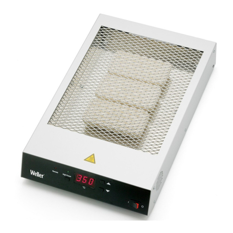
Weller whp 200 User manual

WHP 200
Betriebsanleitung - Mode d’emploi - Gebruiksaanwijzing - Istruzioni per l’uso - Operating
Instructions - Instruktionsbok - Manual de uso - Betjeningsvejledning - Manual do utilizador -
Käyttöohjeet - √‰ËÁ›Â˜ §ÂÈÙÔ˘ÚÁ›·˜ - Kullan∂m k∂lavuzu -
Návod k pouÏití - Instrukcja obs∏ugi -
Üzemeltetési utasítás - Návod na pouÏívanie - Navodila za uporabo - Kasutusjuhend -
Naudojimo instrukcija - Lieto‰anas instrukcija -
Ръководство за работа
- Manual de exploatare
Naputak za rukovanje
www.GlobalTestSupply.com
Find Quality Products Online at: sales@GlobalTestSupply.com

D
F
NLNL
I
GB FIN
P
DK
E
SGR
TR
CZ
PL
H
SK
SLO
EST
LT
LV
USA
CN
IL
RO
HR BG
D
F
NL
I
GB FIN
P
DK
E
SGR
TR
CZ
PL
H
SK
SLO
EST
LT
LV
USA
CN
IL
RO
HR BG
D
F
NL
I
GB FIN
P
DKDK
E
SGR
TR
CZ
PL
H
SK
SLO
EST
LT
LV
USA
CN
IL
RO
HR BG
D
F
NL
I
GB FIN
P
DK
E
SGR
TR
CZ
PL
H
SK
SLO
EST
LT
LV
USA
CN
IL
RO
HR BG
D
F
NL
I
GB FINFIN
P
DK
E
SGR
TR
CZ
PL
H
SK
SLO
EST
LT
LV
USA
CN
IL
RO
HR BG
D
F
NL
I
GB FIN
P
DK
E
SGR
TR
CZ
PL
H
SK
SLO
EST
LT
LV
USA
CN
IL
RO
HR BG
D
F
NL
I
GB FIN
P
DK
E
SGR
TR
CZ
PL
H
SK
SLO
EST
LT
LV
USA
CN
IL
RO
HR BG
D
F
NL
I
GB FIN
P
DK
E
SGR
TR
CZ
PL
H
SK
SLO
EST
LT
LV
USA
CN
IL
RO
HR BG
D
F
NL
I
GBGB FIN
P
DK
E
SGR
TR
CZ
PL
H
SK
SLO
EST
LT
LV
USA
CN
IL
RO
HR BG
D
F
NL
I
GB FIN
P
DK
E
SGR
TR
CZ
PL
H
SK
SLO
EST
LT
LV
USA
CN
IL
RO
HR BG
D
F
NL
I
GB FIN
P
DK
E
SGR
TRTR
CZ
PL
H
SK
SLO
EST
LT
LV
USA
CN
IL
RO
HR BG
D
F
NL
I
GB FIN
P
DK
E
SGRGR
TR
CZ
PL
H
SK
SLO
EST
LT
LV
USA
CN
IL
RO
HR BG
Inhaltsverzeichnis Seite
1. Achtung! 1
2. Beschreibung Technische Daten 1
3. Inbetriebnahme 1
4. Fehleranzeige im Display (1) 1
5. Power On Routinen 1
6. Leiterplattenhalter 1
7. Lieferumfang 1
Table des matières Page
1. Attention! 2
2. Description Caractéristiques techniques 2
3. Mise en service 2
4. Affichages d’erreurs sur l’écran de visualisation (1) 2
5. Fonctions “power on” 2
6. Support de circuit imprimé 2
7. Étendue de livraison 2
Inhoudsopgave Pagina
1. Opgelet! 3
2. Beschrijving Technische gegevens 3.
3. Ingebruikneming 3
4. Foutmeldingen op het display (1) 3
5. Power On Routines 3
6. Printplaathouder 3
7. Levering 3
Indice Pagina
1. Attenzione! 4
2. Descrizione Dati tecnici 4
3. Messa in funzione 4
4. Messaggi d’errore sul display (1) 4
5. Routine di accensione (Power On) 4
6. Supporto circuito stampato 4
7. Materiale in dotazione 4
Table of contents Page
1. Attention! 5
2. Description Technical data 5
3. Placing in operation 5
4. Error indications on the display (1) 5
5. Power- on routines 5
6. PCB holder 5
7. Items supplied 5
Innehållsförteckning Sida
1. Observera! 6
2. Beskrivning Tekniska data 6
3. Idrifttagning 6
4. Felvisningar i display (1) 6
5. Power On-rutin 6
6. Kretskortshållare 6
7. Leveransomfattning 6
Índice Página
1. Atención! 7
2. Descripción Datos técnicos 7
3. Puesta en marcha 7
4. Indicación de fallos en la pantalla de visualización (1) 7
5. Power On Routine 7
6. Soporte para circuitos impresos 7
7. Volumen de suministro 7
Indholdsfortegnelse Side
1. Bemærk! 8
2. Beskrivelse Tekniske data 8
3. Ibrugtagning 8
4. Fejlvisning på displayet (1) 8
5. Power On-rutine 8
6. Printkortholder 8
7. Leveringsomfang 8
Índice Página
1. Atenção! 9
2. Descrição Dados técnicos 9
3. Colocação em serviço 9
4. Indicação de erro no mostrador (1) 9
5. Rotina de activação 9
6. Suporte de placas de circuitos impressos 9
7. Equipamento a fornecer 9
Sisällysluettelo Sivu
1. Huomio! 10
2. Tuoteseloste Tekniset tiedot 10
3. Käyttöönotto 10
4. Vikanäytöt - display(1) 10
5. Power on -rutiinit 10
6. Piirilevypidin 10
7. Toimituksen sisältö 10
¶›Ó·Î·˜ ÂÚȯÔÌ¤ÓˆÓ ™ÂÏ›‰·
1. ¶ÚÔÛÔ¯‹! 11
2. ¶ÂÚÈÁÚ·Ê‹ Δ¯ÓÈο ÛÙÔȯ›· 11
3. £¤ÛË Û ÏÂÈÙÔ˘ÚÁ›· 11
4. ∂Ó‰ÂÈÍË ÛÊ¿ÏÌ·ÙÔ˜ ÛÙËÓ ÔıfiÓË (1) 11
5. ƒÔ˘Ù›Ó· Power On 11
6. ™Ù‹ÚÈÁÌ· οÚÙ·˜ Ù˘ˆÌ¤ÓÔ˘ ΢ÎÏÒÌ·ÙÔ˜ 11
7. ™˘Û΢·Û›· ·Ú¿‰ÔÛ˘ 11
Íçindekiler Sayfa
1. Dikkat! 12
2. Aç∂klama Teknik bilgiler 12
3. Ílk çal∂μt∂rma 12
4. Ekrandaki (1) ar∂za görüntüleri 12
5. Power On Rutini 12
6. Devre kartı tutucusu 12
7. Sevkiyat kapsam∂ 12
www.GlobalTestSupply.com
Find Quality Products Online at: sales@GlobalTestSupply.com

D
F
NL
I
GB FIN
P
DK
E
SGR
TR
CZ
PL
H
SK
SLOSLO
EST
LT
LV
USA
CN
IL
RO
HR BG
D
F
NL
I
GB FIN
P
DK
E
SGR
TR
CZ
PL
H
SK
SLO
ESTEST
LT
LV
USA
CN
IL
RO
HR BG
D
F
NL
I
GB FIN
P
DK
E
SGR
TR
CZ
PL
H
SK
SLO
EST
LT
LV
USA
CN
IL
RO
HR BG
D
F
NL
I
GB FIN
P
DK
E
SGR
TR
CZ
PL
H
SK
SLO
EST
LT
LV
USA
CN
IL
RO
HR BG
D
F
NL
I
GB FIN
P
DK
E
SGR
TR
CZ
PL
H
SKSK
SLO
EST
LT
LV
USA
CN
IL
RO
HR BG
D
F
NL
I
GB FIN
P
DK
E
SGR
TR
CZCZ
PL
H
SK
SLO
EST
LT
LV
USA
CN
IL
RO
HR BG
D
F
NL
I
GB FIN
P
DK
E
SGR
TR
CZ
PLPL
H
SK
SLO
EST
LT
LV
USA
CN
IL
RO
HR BG
D
F
NL
I
GB FIN
P
DK
E
SGR
TR
CZ
PL
H
SK
SLO
EST
LT
LV
USA
CN
IL
RO
HR BG
D
F
NL
I
GB FIN
P
DK
E
SGR
TR
CZ
PL
H
SK
SLO
EST
LT
LV
USA
CN
IL
RO
HR BGBG
D
F
NL
I
GB FIN
P
DK
E
SGR
TR
CZ
PL
H
SK
SLO
EST
LT
LV
USA
CN
IL
RORO
HR BG
D
F
NL
I
GB FIN
P
DK
E
SGR
TR
CZ
PL
H
SK
SLO
EST
LT
LV
USA
CN
IL
RO
HRHR BG
Turinys Puslapis
1. Dòmesio! 19
2. Apra‰ymas Techniniai duomenys 19
3. Pradedant naudoti 19
4. Klaid˜ parodymas displòjuje (1) 19
5. Øjungimo eiga 19
6. Spausdintini˜ plok‰ãi˜ laikiklis 19
7. Tiekiamas komplektas 19
Satura RÇd¥tÇjs
1. Uzman¥bu! 20
2. Apraksts Tehniskie dati 20
3. Sagatavo‰ana darbam 20
4. K∫das rÇd¥jumi uz displeja (1) 20
5. Power On Routine 20
6. Vad¥tÇju pla‰u turïtÇjs 20
7. PiegÇdes komplekts 2
ъдържание страница
1.нимание! 20
2.Описание ехнически данни 20
3.апочване на работа 20
4.ндикация на неизправности на дисплея (1) 20
5.Power On Routinen 20
6.ържач на платката 20
7.Обем на доставката 20
Cuprins Pagina
1.Atenie! 21
2.Descriere Date tehnice 21
3.Punere în funciune 21
4.Afişarea erorilor pe display (1) 21
5.Secvenţe fixe Power On 21
6.Suport placa cu circuite imprimate 21
7.Volumul de livrare 21
Sadržaj Stranica
1.Pažnja! 22
2.Opis Tehnički podaci 22
3.Puštanje u pogon 22
4.Prikaz pogrešaka na zaslonu (1) 22
5.Rutine Power On 22
6.Držač tiskane pločice 22
7.Opseg isporuke 22
Obsah Strana
1. Pozor! 13
2. Popis Technické údaje 13
3. Uvedení do provozu 13
4. Zobrazení chyb na displeji (1) 13
5. Zapínací (Power On) rutina 13
6. DrÏák desek ti‰tûn˘ch spojÛ 13
7. Rozsah dodávky 13
Spis treÊci Strona
1. Uwaga! 14
2. Opis Dane techniczne 14
3. Uruchomienie 14
4. Wskazania b∏ dów na wyÊwietlaczu (1) 14
5. Procedura Power On 14
6. Uchwyt do p∏ytek drukowanych 14
7. Zakres wyposa˝enia 14
Tartalomjegyzék Oldal
1. Figyelem! 15
2. Leírás Mıszaki adatok 15
3. Üzembevétel 15
4. Hibakijelzés a kijelzŒn (1) 15
5. Power On rutinok 15
6. Nyomtatott áramkör tartó 15
7. Szállítási terjedelem 15
Obsah Strana
1. Upozornenie 16
2. Popis Technické údaje 16
3. Uvedenie do prevádzky 16
4. Chybové hlásenia na disple ji (1) 16
5. Zapínacia (Power On) rutina 16
6. DrÏiak dosák tlaãen˘ch spojov 16
7. Rozsah dodávky 16
Vsebina Stran
1. Pozor! 17
2. Tehniãni opis Tehniãni podatki 17
3. Pred uporabo 17
4. Prikaz napak na ekranu (1) 17
5. Postopki ob vklopu 17
6. Nosilec plo‰ãe z vodniki 17
7. Obseg dobave 17
Sisukord Lehekülg
1. Tähelepanu! 18
2. Kirjeldus Tehnilised andmed 18
3. Kasutuselevõtt 18
4. Veateated ekraanil (1) 18
5. Power On programm 18
6. Juhtplaadihoidik 18
7. Tarne sisu 18
www.GlobalTestSupply.com
Find Quality Products Online at: sales@GlobalTestSupply.com

D
F
NL
I
GB FIN
P
DK
E
SGR
TR
CZ
PL
H
SK
SLO
EST
LT
LV
USA
CN
IL
RO
HR BG
D
F
NL
I
GBGB FIN
P
DK
E
SGR
TR
CZ
PL
H
SK
SLO
EST
LT
LV
USA
CN
IL
RO
HR BG
D
F
NL
I
GB FIN
P
DK
E
SGR
TR
CZ
PL
H
SK
SLO
EST
LT
LV
USA
CN
IL
RO
HR BG
D
F
NLNL
I
GB FIN
P
DK
E
SGR
TR
CZ
PL
H
SK
SLO
EST
LT
LV
USA
CN
IL
RO
HR BG
D
F
NL
I
GB FIN
P
DK
E
SGR
TR
CZ
PL
H
SK
SLO
EST
LT
LV
USA
CN
IL
RO
HR BG
D
F
NL
I
GB FIN
P
DK
E
SGR
TR
CZ
PL
H
SK
SLO
EST
LT
LV
USA
CN
IL
RO
HR BG
1. Écran de visualisation (affichage sur
3 chiffres et 7 segments)
2. Touche « UP »
3. Commutateur d’alimentation
4. Touche « DOWN »
5. Contrôle optique de régulation
6. Raccoordement au secteur
1. Display (3-stellige 7-Segmentanzeige)
2. “UP” Taste
3. Netzschalter
4. “DOWN” Taste
5. Optische Regelkontrolle
6. Netzanschluss
1. Display (3-posities, 7-segmentweergave)
2. “UP” toets
3. Netschakelaar
4. “DOWN” toets
5. Optische regelcontrole
6. Netaansluiting
1. Display (3-digit 7-segment display)
2. “UP” button
3. Mains switch
4. “DOWN” button
5. Optical indication of the state of
regulation
6. Mains connection
1. Display alfa numerico (indicazione a
7 segmenti e 3 cifre)
2. Tasto “UP”
3. Interruttore di rete
4. Tasto “DOWN”
5. Controllo di regolazione ottico
6. Allacciamento alla rete
1. Display (3-siffrig 7-segmentsvisning)
2. ”UP”-knapp
3. Strömbrytare
4. ”DOWN”-knapp
5. Optisk justeringskontroll
6. Elanslutning
www.GlobalTestSupply.com
Find Quality Products Online at: sales@GlobalTestSupply.com

D
F
NL
I
GB FIN
P
DK
E
SGR
TR
CZ
PL
H
SK
SLO
EST
LT
LV
USA
CN
IL
RORO
HR BG
1. Displejs (tr¥sviet¥gs 7 segmentu
rÇd¥tÇjs)
2. "UP" tausti¿‰
3. Elektr¥bas t¥kla slïdzis
4. "DOWN" tausti¿‰
5. OptiskÇs regulï‰anas kontrole
6. Pieslïgums t¥klam
D
F
NL
I
GB FIN
P
DK
E
SGR
TR
CZ
PL
H
SK
SLO
ESTEST
LT
LV
USA
CN
IL
RO
HR BG
D
F
NL
I
GB FIN
P
DK
E
SGR
TR
CZ
PL
H
SK
SLOSLO
EST
LT
LV
USA
CN
IL
RO
HR BG
D
F
NL
I
GB FIN
P
DK
E
SGR
TR
CZ
PL
H
SKSK
SLO
EST
LT
LV
USA
CN
IL
RO
HR BG
D
F
NL
I
GB FIN
P
DK
E
SGR
TRTR
CZ
PL
H
SK
SLO
EST
LT
LV
USA
CN
IL
RO
HR BG
D
F
NL
I
GB FIN
P
DK
E
SGRGR
TR
CZ
PL
H
SK
SLO
EST
LT
LV
USA
CN
IL
RO
HR BG
D
F
NL
I
GB FINFIN
P
DK
E
SGR
TR
CZ
PL
H
SK
SLO
EST
LT
LV
USA
CN
IL
RO
HR BG
D
F
NL
I
GB FIN
P
DK
E
SGR
TR
CZ
PL
H
SK
SLO
EST
LT
LV
USA
CN
IL
RO
HR BG
D
F
NL
I
GB FIN
P
DKDK
E
SGR
TR
CZ
PL
H
SK
SLO
EST
LT
LV
USA
CN
IL
RO
HR BG
D
F
NL
I
GB FIN
P
DK
E
SGR
TR
CZ
PL
H
SK
SLO
EST
LT
LV
USA
CN
IL
RO
HR BG
1. Display (3-cifret 7-segment-display)
2. ”UP”-tast
3. Netafbryder
4. ”DOWN”-tast
5. Optisk regulatorkontrol
6. Nettilslutning
1. Pantalla de visualización (indicación de
7 segmentos de tres dígitos)
2. Tecla “UP”
3. Interruptor de red
4. Tecla “DOWN”
5. Control óptico de regulación
6. Conexión de red
1. Mostrador (7 segmentos com 3 dígitos)
2. Tecla “UP”
3. Interruptor de rede
4. Tecla “DOWN”
5. Controlo de regulação óptica
6. Ligação à rede
1. √ıfiÓË (¤Ó‰ÂÈÍË 3 „ËÊ›ˆÓ Î·È 7 ÛÙÔȯ›ˆÓ)
2. ¶Ï‹ÎÙÚÔ "UP"
3. ¢È·ÎfiÙ˘ ‰ÈÎÙ‡Ô˘
4. ¶Ï‹ÎÙÚÔ "DOWN"
5. √ÙÈÎfi˜ ¤ÏÂÁ¯Ô˜ Ú‡ıÌÈÛ˘
6. ™‡Ó‰ÂÛË ‰ÈÎÙ‡Ô˘
1. näyttö (3-merkkiä, 7 näyttösegmenttiä)
2. UP-painike
3. verkkokytkin
4. DOWN-painike
5. optinen säädöntarkkailu
6. verkkoliitäntä
1. Ekran (3 basamakl∂, 7 segmentli
gösterge)
2. "YUKARI" tuμu
3. Fiebeke μalteri
4. "Aμaπi" tuμu
5. Görsel ayar kontrolü
6. Fiebeke baπlant∂s∂
D
F
NL
I
GB FIN
P
DK
E
SGR
TR
CZCZ
PL
H
SK
SLO
EST
LT
LV
USA
CN
IL
RO
HR BG
D
F
NL
I
GB FIN
P
DK
E
SGR
TR
CZ
PLPL
H
SK
SLO
EST
LT
LV
USA
CN
IL
RO
HR BG
D
F
NL
I
GB FIN
P
DK
E
SGR
TR
CZ
PL
H
SK
SLO
EST
LT
LV
USA
CN
IL
RO
HR BG
1. WyÊwietlacz (3-pozycyjny
7-segmentowy)
2. Przycisk UP
3. W∏àcznik sieciowy
4. Przycisk DOWN
5. Optyczna kontrola regulacji
6. Przy∏àcze sieciowe
1. KijelzŒ (3-karakteres
7-szegmenses kijelzŒ)
2. UP gomb
3. hálózati kapcsoló
4. DOWN gomb
5. Optikai szabályozóellenŒrzŒ
6. Hálózati csatlakozás
1. Displej (3místn˘ 7segmentov˘ displej)
2. Tlaãítko UP
3. SíÈov˘ vypínaã
4. Tlaãítko DOWN
5. Optická kontrola regulace
6. SíÈová pfiípojka
1. Displej (3-miestny, kaÏdá ãíslica je
zloÏená zo 7segmentov)
2. Tlaãidlo UP
3. SieÈov˘ vypínaã
4. Tlaãidlo DOWN
5. Optická kontrola regulácie
6. SieÈová prípojka
1. Ekran (3-mestni, 7-segmentni prikaz)
2. Tipka UP
3. OmreÏno stikalo
4. Tipka DOWN
5. Vizualna kontrola krmiljenja
6. OmreÏni prikljuãek
1. Ekraan (3-kohaline
7-segmendiline näidik)
2. "UP" klahv
3. Võrgulüliti
4. "DOWN" klahv
5. Optiline reguleerimiskontroll
6. Võrgupistik
D
F
NL
I
GB FIN
P
DK
E
SGR
TR
CZ
PL
H
SK
SLO
EST
LT
LV
USA
CN
IL
RO
HR BG
D
F
NL
I
GB FIN
P
DK
E
SGR
TR
CZ
PL
H
SK
SLO
EST
LT
LV
USA
CN
IL
RO
HR BG
1. Displòjus (trij˜ skaitmen˜, septyni˜
segment˜ indikatorius)
2. „UP" mygtukas
3. Tinklo jungiklis
4. „DOWN" mygtukas
5. Optinò valdymo kontrolò
6. Lizdas elektros tinklo prijun gimui
1. исплей (7-сегментна индикация,
3-цифрена )
2. #утон UP
3. %режов прекъсвач
4. #утон DOWN
5. Оптичен контрол на регулирането
6. #укса за включване в мрежата
1. Display (afişare 7 segmente, 3 caractere)
2. Tasta UP
3. Comutator de reea
4. Tasta DOWN
5. Controlul optic al setării
6. Racord la reea
D
F
NL
I
GB FIN
P
DK
E
SGR
TR
CZ
PL
H
SK
SLO
EST
LT
LV
USA
CN
IL
RO
HR BGBG
D
F
NL
I
GB FIN
P
DK
E
SGR
TR
CZ
PL
H
SK
SLO
EST
LT
LV
USA
CN
IL
RO
HRHR BG
1. Zaslon (3-znamenkasti prikaz u
7 segmenata)
2. Tipka UP
3. Mrežna sklopka
4. Tipka DOWN
5. Optička kontrola upravljanja
6. Mrežni priključak
www.GlobalTestSupply.com
Find Quality Products Online at: sales@GlobalTestSupply.com

WHP 200
Accessories
Easy fix board holder
Code No.: T0058757875
www.GlobalTestSupply.com
Find Quality Products Online at: sales@GlobalTestSupply.com

2
Français
Nous vous remercions pour la confiance que vous nous avez
témoignée en achetant la platine chauffante Weller
WHP 200. La fabrication a été soumise au respect des exi-
gences de qualité les plus sévères assurant un fonctionne-
ment impeccable de l’appareil et permettant d’obtenir des
résultats de soudage optimaux.
1. Attention!
Avant la mise en service de l'appareil, veuillez lire attentive-
ment le présent mode d'emploi de même que les consignes
de sécurité jointes. La non observation des consignes de
sécurité peut être à l'origine d'un danger de blessure et de
mort.
Le fabricant décline toute responsabilité en cas d'utilisation
de l'appareil à des fins autres que celles décrites dans le
mode d'emploi et en cas de modifications effectuées sans
son accord.
La platine chauffante WELLER WHP 200 correspond à la
déclaration de conformité CE suivant les exigences fonda-
mentales de sécurité des directives 2004/108/CE et
2006/95/CE.
2. Description
La platine chauffante WHP 200 est équipée d'un émetteur
infrarouge 200 W à haute température et donnent à l’utilisa-
teur de nombreuses possibilités pour le préchauffage de
sous-groupes électroniques. L'émetteur à haute températu-
re délivre son énergie essentiellement dans la plage de lon-
gueur d'ondes de 2 à 10 µm est assure un réchauffage rapi-
de et efficace des matériaux modernes. Une électronique de
régulation numérique garantit un comportement thermique
précis.
Caractéristiques techniques
Dimensions: 165 x 195 x 70 mm
(L x l x H) 6,5 x 7,68 x 2,75 inch
Tension secteur: 230 V (120 V); 50 Hz (60 Hz)
Puissance: Zone de chauffage 200 W
Plage de températures: 50°C - 400°C (150°F - 750°F)
Classe de protection: 1
Zone de chauffage: 120 (4,72) x 60 (2,36) mm (inch)
3. Mise en service
Mettre tous les objets sensibles à la température et suscep-
tibles de brûler hors de proximité de la platine chauffante.
S’assurer que la platine chauffante soit débranchée. Veiller à
ce que la tension secteur soit correcte. Connecter l’appareil
au secteur (6). Mettre l’appareil sous tension avec le com-
mutateur d’alimentation (3). Lors de la mise sous tension de
l’appareil, un autotest mettant en route tous les éléments de
l’écran de visualisation (1) est lancé. Ensuite, la températu-
re réglée (valeur nominale) et la version de
température (°C / °F) sont affichés pour un court instant.
Ensuite, l’écran de visualisation passe automatiquement à
l’affichage de valeur effective. Le point rouge de l’écran de
visualisation (5) s’allume. Ce point sert de contrôle optique
de régulation. Un allumage permanent signifie que le
système chauffe.Un clignotement signifie que la températu-
re de service est atteinte.
3.1. Réglage de température
L’écran de visualisation numérique (1) indique toujours la
valeur réelle de température. En actionnant la touche « UP »
ou « DOWN » (2)(4), l’écran de visualisation numérique (1)
passe à la valeur nominale actuellement réglée. La valeur
nominale réglée (affichage clignotant) peut être modifiée uni-
quement en appuyant ponctuellement ou continuellement sur
la touche « UP » ou « DOWN » (2)(4) dans la direction cor-
respondante. Si la touche est enfoncée en permanence, la
valeur nominale change en défilement rapide. Environ 2 sec.
après le relâchement, l’écran de visualisation numérique (1)
repasse automatiquement à la valeur réelle.
3.2. Déconnexion manuelle de température (OFF)
Appuyer simultanément sur la touche «UP» et «DOWN» pour
déconnecter la température. « OFF » apparaît sur l’écran de
visualisation (1).
4. Affichages d’erreurs dans l’écran
de visualisation (1)
- - - Aucun capteur de température détecté
E10 Température maximale de boîtier dépassée
5. Fonction « power on »
Commutation °C / °F
Pour cela, tout d’abord mettre l’appareil hors tension via le
commutateur d’alimentation (3). Appuyer sur la touche
DOWN (4) et mettre l’appareil sous tension. Maintenir la tou-
che enfoncée jusqu’à ce que “°F ” apparaisse à l’écran de
visualisation (1). Le réglage est enregistré en relâchant la
touche « DOWN ». Même procédure pour la conversion sur
«°C».
6. Support de circuit imprimé
Le support de circuit imprimé est fixé au-dessus de la zone
de chauffage sur la partie supérieure du boîtier. Pour fixer,
retirer ou déplacer le support de circuit imprimé, desserrer
les vis moletées.
7. Étendue de livraison
Platine chauffante WHP 200
Câble d’alimentation
Support de circuit imprimé
Mode d'emploi; Consignes de sécurité
Sous réserve de modifications techniques!
Vous trouverez les manuels d'utilisation actualisés sur
www.GlobalTestSupply.com
Find Quality Products Online at: sales@GlobalTestSupply.com

5
We thank for the confidence you have shown by purchasing
the Weller Heating Plate WHP 200. During manufacture the
strictest quality requirements are applied; these assure the
correct function of the device and make it possible to obtain
optimal soldering results.
1. Attention!
Prior to placing the device in operation, please carefully read
these operating instructions and the safety instructions
enclosed. If the safety instructions are not observed, there is
a risk of injury.
The manufacturer accepts no liability for usage other than
that described in the operating instructions or for unautho-
rised modifications
The WELLER heating plate WHP 200 complies with the
EU declaration of conformity as per the essential safety
requirements in the directives 2004/108/EU and
2006/95/EU.
2. Description
The WHP 200 heating plate is equipped with a 200 W
infrared high-temperature lamp and enables the user to pre-
heat electronic assemblies in numerous ways. The high-
temperature lamp supplies energy primarily in the wave-
length range of 2 - 10 m and heats modern tools quickly
and efficiently. Digital regulation electronics ensure precise
temperature behaviour.
Technical data
Dimensions: 165 x 195 x 70 mm
(W x L x H) 6,5 x 7,68 x 2,75 inch
Mains voltage: 230 V (120 V); 50 Hz (60 Hz)
Power: Heating zone 200 W
Temperature range: 50°C - 400°C (150°F - 750°F)
Protection class: 1
Heating zone: 120 (4,72) x 60 (2,36) mm (inch)
3. Placing in operation
Remove all temperature sensitive and flammable objects
from the vicinity of the heating plate. Ensure that the heating
plate is switched off. Ensure that the mains voltage is cor-
rect. Connect the device to the mains (6). Switch on the
device at the mains switch (3). When the device is switched
on, a self-test is performed during which all display ele-
ments (1) are operated. The temperature set (setpoint) and
the temperature scale (°C / °F) are then displayed briefly.
The display then switches automatically to the indication of
the actual value. The red dot on the display illuminates (5).
This dot is a visual indication of the state of the regulation.
Continuous illumination indicates the system is warming up.
Flashing indicates that the operating temperature has been
reached.
3.1. Adjusting temperature
The digital display (1) normally indicates the actual temper-
ature. The digital display (1) switches to the current setpoint
when the ”UP” or “DOWN” button (2)(4) is pressed. The set-
point (flashing indication) can now be changed as required
by pressing or pressing and holding the “UP” or “DOWN”
button (2)(4). If the button is pressed and held down, the set-
point changes quickly. Approx. 2 sec. after the button is
released, the digital display (1) automatically switches back
to the actual value.
3.2. Manual heating shut down (OFF)
The device heating is shut down by simultaneously pressing
the “UP” and “DOWN” buttons. "Off" appears on the display
(1).
4. Error indications on the display (1)
- - - No temperature sensor detected
E10 Maximum housing temperature exceeded
5. Power-on routine
°C / °F change over
For this purpose the device is first switched off at the mains
switch (3). Press DOWN button (4) and switch on the device.
Keep button pressed until the “°F” appears on the dis-
play (1). When the “DOWN” button is released the setting is
saved. Use the same procedure for the change over to “°C”.
6. PCB holder
The PCB holder is secured to the housing upper section by
the Heizone. For securing, removing or adjusting the PCB
holder, release the knurled screws.
7. Items supplied
WHP 200 heating plate
Mains cable
PCB holder
Operating instructions
Safety information
Subject to technical change without notice!
See the updated operating instructions at
English
www.GlobalTestSupply.com
Find Quality Products Online at: sales@GlobalTestSupply.com

24
Circuit Diagram
www.GlobalTestSupply.com
Find Quality Products Online at: sales@GlobalTestSupply.com
Other manuals for whp 200
1
This manual suits for next models
2
Other Weller Heater manuals