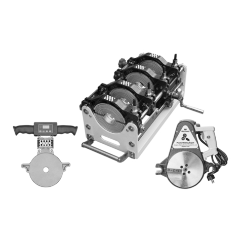
Welping WP250A User manual

HANGZHOU WEIPING MACHINERY EQUIPMENT CO., LTD
Room 1904 Building 1, Taifu Plaza, No. 1 Tonghui Middle Road, Chengxiang Street, Xiaoshan District, Hangzhou
www.welpingtool.com top@welping.cn
Operator’s Manual
Hydraulic Butt fusion welding machine
For Model: WP160A-1600A
WP160B-630B
WARNING!
Read this Operator’s Manual
carefully before using the
tool. Failure to understand
and follow the instructions of
this manual may result in
electrical shock, fire and/or
serious personal injury.

www.welpingtool.com
Overview of Fusion operation
The operation of heat fusion is to heat two pipe end surfaces to a specified temperature,
then fuse them together by application of certain force. This will develop pressure which
causes flow of the melted material, which causes mixing and thus fusion. When the
thermoplastic material is heated, the molecular structure is transformed into an amorphous
condition. When fusion pressure is applied, the molecules from each thermoplastic part mix
together. As the joint cools, the molecules return to the solid form, the original interfaces are
gone, and the fitting and pipe have become one complete unit. A strong, fully leak-tight
connection is the result.
Major operations include:
Clamping
The pipes are held axially and radially for all subsequent operations to follow
Planing
The pipe ends are planed (trimmed, faced) to establish clean, parallel jointing
surfaces perpendicular to the center line of the pipes
Aligning
The pipe ends are aligned with each other to minimize mismatch of the pipe
walls.
Heating
A melt pattern that penetrates into the pipe is formed around both pipe ends
Fusing
The melted pipe ends are joined under specified force, which is constant
around the pipe interfacial area.
Cooling
The fusion joint is held immobile under specified pressure until adequately
cooled.
Inspecting
Visually examine the outlook of the joint for compliance with the standard or
fusion procedure used.
Thank you for choosing WELPING
The A series butt fusion machines allow operators to butt fuse pipe(PE, HDPE, PP, MPP, PVDF)
in the thermoplastic piping jobs. With it’s compact design and optimal weight, it is an easy
machine to operate when performing fusions in tight spaces as well as on the ground.
The A series machines utilizes the enclosure type hydraulic station to provide hydraulic
power to the carriage (frame). The enclosure design can shield splash and dirt in field
operation. The Robust carriage (frame) part can withstand heavy duty jobs, free from
distortion and breakage. Color LCD screen provides clear and sharp display in different
environments.
With reasonable care and maintenance, the machine will give years of satisfactory service.
Before operating this machine, please read this manual thoroughly, and keep a copy with the
machine for future reference.
When fusing thermoplastic pipe materials, refer to the pipe manufacturer's fusion
procedures or appropriate joining standard.
Model
Fusion range (mm)
Standard reducers (mm)
WP160A/B
63-160
(50) 63-75-90-110-125-140-160
WP200A/B
63-200
63-75-90-110-125-140-160-180-200

www.welpingtool.com
WP250A/B
90-250
(63-75) 90-110-125-140-160-180-200-225-250
WP315A/B
90-315
90-110-125-140-160-180-200-225-250-280-315
WP355A/B
160-355
(110-125) 140-160-180-200-225-250-280-315-355
WP400A/B
180-400
180-200-225-250-280-315-355-400
WP450A/B
200-450
(180) 200-225-250-280-315-355-400-450
WP500A/B
200-500
(180-200-225) 250-280-315-355-400-450-500
WP630A/B
315-630
315-355-400-450-500-560-630
WP800A
500-800
(450-500-560) 630-710-800
WP1000A
800-1000
(630-710) 800-900-1000
WP1200A
1000-1200
(800-900) 1000-1100-1200
WP1600AH
1400-1600
(1000) 1200-1400-1600
Sizes those are in (**) are optional.
Read and Understand
Do not operate this equipment until you have carefully read, and understand all the sections
of this manual, and all other equipment manuals that will be used with it.
Your safety and the safety of others depends upon care and judgment in the operation of
this equipment.
Follow all applicable local, and industry specific regulations.
WELPING cannot anticipate every possible circumstance that might involve a potential
hazard. The warnings in this manual and on the machine are therefore not all inclusive.
You must satisfy yourself that a procedure, tool, work method, or operating technique is safe
for you and others. You should also ensure that the machine will not be damaged or made
unsafe by the method of operation or maintenance you choose.
General Safety
Safety is important. Pay attention to anything unusual that you notice during set up or
operation.
LISTEN for thumps, bumps, rattles, squeals, air leaks, or unusual sounds.
SMELL odors like burning insulation, hot metal, burning rubber etc.

www.welpingtool.com
FEEL any changes in the way the equipment operates.
SEE problems with wiring and cables, hydraulic connections, or other equipment.
REPORT anything you see, feel, smell, or hear that is different from what you expect, or that
you think may be unsafe.
Work Area Safety
• Keep work area clean and well lit. Cluttered or dark areas invite accidents.
• Do not operate the butt welder in explosive atmospheres, such as in the presence of
flammable liquids, gases or dust. The heat may ignite the dust or fumes.
• Keep children and bystanders away while operating the butt welding machine. Distractions
can cause you to lose control.
Personal Safety
• Wear a hard hat, safety shoes, safety glasses, and other applicable personal protective
equipment.
• Remove hanging jewelry and rings, and do not wear loose-fitting clothing or long hair that
could catch on controls or moving machinery.
Electrical Safety
• Always ensure equipment is properly grounded. It is important to remember that if you are
working in a wet environment with electrical devices. Proper ground connections help to
minimize the chances of an electric shock.
• Frequently inspect electrical cords and unit for damage. Have damaged components
replaced and service performed by a qualified electrician.
• Do not abuse the cord. Keep cord away from heat, oil, sharp edges or moving parts.
Damaged or entangled cords increase the risk of electric shock.
NOTICE: Always connect units to the proper power source as listed on the unit, or in the
owner's manual. Use GFCI electrical connections when available or required.
Butt Fusion Machine Use and Care
• Facer blades are sharp and can cut. Never attempt to remove blades while the facer
(planing tool) is running, or is in the facing position between the clamps. Use care when
operating the facer, and when handling the unit.
• The heater is hot and will burn clothing and skin. Keep the heater in its insulated heater
stand or blanket when not in use, and use care when heating the pipes.
• Do not use the butt welder if the switch does not turn it ON and OFF. Any welder that
cannot be controlled with the switch is dangerous and must be repaired.
• Maintain butt welder and accessories. Check for misalignment or binding of moving parts,
breakage of parts and any other condition that may affect the operation. If damaged, have
the tool repaired before use. Many accidents are caused by poorly maintained tools.

www.welpingtool.com
Butt Welding Procedures:
P1: Welding pressure (Mpa)
P2: Total pressure, P2=P1+Pt
(Mpa)
Pt: Drag pressure (Mpa)
t1: The time for the welding bead
reaching specific height
t2: Heat soaking time (s) = pipe
wall thickness (mm)×10
t3: Change-over time (s)
t4: Pressure build up time (s)
t5: Cooling time (min)
Pipe inspection
Before welding, first check if the pipe material and pressure setting are correct. Secondly
check if there are obvious scratches or fissures on the surface of pipes/fittings. If the depth of
scratches or fissures exceeds 10% of the wall thickness, cut the damaged section of pipe.
Clear the pipe end surfaces with clean cloth.
Pipe clamping
Place the pipes/fittings into reducers (inserts) of carriage (frame) and leave enough length of
pipe to be welded. If the pipe out of the main frame is too long, it should be supported to
keep level with the machine. Fasten the screws of clamps to fix the pipes/fittings.
Pipe milling (facing, or planing)
Put the milling cutter (facer) between the pipes/fittings ends and switch on. Assure the
pressure selector control is in the facing position. Move the carriage directional control to
close the carriage. If the facer stalls, adjust the facing pressure so the facer continues to cut.
Shift the carriage directional control to the neutral position. Allow the facer to run for several
revolutions to ensure that there are no chips hanging on the end of the pipe.Turn facer off.
Close the pipes/fitting ends and checks the alignment of pipes. The max misalignment
should not exceed 10% of the wall thickness, and it could be improved by loosening or
tightening the screws of clamps. The gap between two pipe ends should not exceed 10% of
wall thickness; otherwise the pipes/fittings should be faced again.
Pipe heating
Clear the dust and dirt on the surface of heating plate (Caution: Don’t damage PTFE layer),
and make sure the temperature has reached the required level.
Put the heating plate between the pipe ends after it reaches required temperature. Close the
carriage (frame) to bring pipe ends in contact with the heater. Allow for bead-up according
to pipe manufacturer's or appropriate joining standard recommendations.

www.welpingtool.com
Ensure the heater stays perpendicular to the pipe by supporting the heater during the
heating process.
NOTICE: Ensure that the pipe remains in contact with heater throughout the entire process.
Pipe fusing
Shift the carriage directional control to the neutral position. Open the carriage (frame) just
enough to remove the heater. Quickly remove the heater. Inspect pipe ends for appropriate
melt. Quickly close the carriage, bringing the pipe ends together under the fusion pressure.
Allow joint to cool under pressure according to pipe manufacturer's recommendations.
When it reaches the required cooling time, loosen the screw of clamps and then takes out
the jointed pipes.
Reference for Welding Parameters
Total sectional of cylinders
Model
Value (cm2)
WP160A/B
15.32
WP200A/B
15.32
WP250A/B
11
WP315A/B
20.02
WP355A/B
20.02
WP400A/B
22.38
WP450A/B
22.38
WP500A/B
22.38
WP630A/B
27.1
WP800A
31.8
WP1000A
36.52
WP1200A
45.94
WP1600AH
15.32
Wall
thickness
(mm)
Bead
height
(mm)
Bead
build-up
pressure
(MPa)
Soaking
time
t2(sec)
Soaking
pressure
(MPa)
Change-over
time
t3(sec)
Pressure build
-up time
t4(sec)
Welding
pressure
(MPa)
Cooling
time
t5
(min)
0~4.5
0.5
0.15
45
≤0.02
5
5
0.15±0.01
6
4.5~7
1.0
0.15
45~70
≤0.02
5~6
5~6
0.15±0.01
6~10
7~12
1.5
0.15
70~120
≤0.02
6~8
6~8
0.15±0.01
10~16
12~19
2.0
0.15
120~190
≤0.02
8~10
8~11
0.15±0.01
16~24
19~26
2.5
0.15
190~260
≤0.02
10~12
11~14
0.15±0.01
24~32
26~37
3.0
0.15
260~370
≤0.02
12~16
14~19
0.15±0.01
32~45
37~50
3.5
0.15
370~500
≤0.02
16~20
19~25
0.15±0.01
45~60
50~70
4.0
0.15
500~700
≤0.02
20~25
25~35
0.15±0.01
60~80

www.welpingtool.com
Remark:Bead build-up pressure and welding pressure in the form is the recommended interface pressure,
the gauge pressure should be calculated with the following formula.
Expressions:
Section of welding pipe ends
welding pressure =× 0.15 + drag pressure (Mpa)
Total section of cylinders
Pipe Joints Visual check
Visually check:round bead, good joint
Narrow and fall bead. Too high pressure while welding
Too small bead. Pressure is not enough while welding
A obvious gap between the welding beads. Temperature is not up
to required figure or change-over time is too long.
High & low bead. Different heating time or fusion temperature
causes that.
◎ Misalignment. Welding under the condition that the
misalignment exceeds 10% of pipe wall thickness while align the
two ends.
Maintenance
1. To ensure optimum performance, the machine must be kept clean and well maintained.
With reasonable care, this machine will give years of service. Therefore, it is important that a
regular schedule of preventive maintenance be kept.
2. Store machine under shelter, out of the weather, whenever possible.
3. The machine can be cleaned if needed with soap and water. Do not pressure wash. Dry
the machine and lubricate some part to keep free of rusting.
4. Pressure gauge should be checked daily. The gauge should read zero when the unit is not
running. Damaged gauges should be replaced.
5. To prevent slippage and ensure proper alignment, the clamping parts and inserts
(reducers) must be clean. Clean the clamping parts and inserts (reducers) of any dirt or
residual material using a stiff-bristled brush.
6. The lock nuts must turn freely. Keep the clamp lock bolt and nuts threads brushed clean.

www.welpingtool.com
Lubricate the threads if needed.
7. Facer (planing tool) blade should be inspected for damage and sharpness. Dull or
chipped blades must be replaced.
NOTICE: Never extend the blade beyond the outer circumference of the facer (planing tool).
8. The heater faces must be kept clean and free of any plastic build up or contamination.
Before each fusion joint the heater surfaces must be wiped with a clean dry lint free
non-synthetic cloth.
NOTICE: Do not use an abrasive pad or steel wool. Use a non synthetic cloth that won't
damage surfaces.
Hangzhou Welping Machinery Equipment Co., Ltd
Phone: 0086-571-89332538 Whatsapp:+86-13185061581
Office address: Room 1904Building 1, Taifu Plaza, No. 1 Tonghui Middle Road,Xiaoshan
District, Hangzhou
Factory address: No. 2 Jinyuan Road, Puyang Town, Xiaoshan District, Hangzhou, China
This manual suits for next models
11
Table of contents
Other Welping Welding System manuals
Popular Welding System manuals by other brands

Metal Man
Metal Man MIG/Stick 200 Operating instructions and parts manual

Air Liquide
Air Liquide SAF SAXOTIG 1600 Safety instruction for use and maintenance

Holzmann
Holzmann EISA162 user manual

Miller
Miller BOBCAT 225G PLUS owner's manual

Migatronic
Migatronic RALLY MIG 161i quick guide

Jasic
Jasic EVO 2.0 TR-01 Assembly instructions

Taurus
Taurus CUT-70I Operation manual

Lincoln Electric
Lincoln Electric POWER WAVE 405 Operator's manual

Miller Electric
Miller Electric LMSW Series Specifications

WELDKAR
WELDKAR WK TIG 2025 AC/DC Pulse instruction manual

Leister
Leister HEMTEK ST operating instructions

Magmate
Magmate MMA 160 operating manual