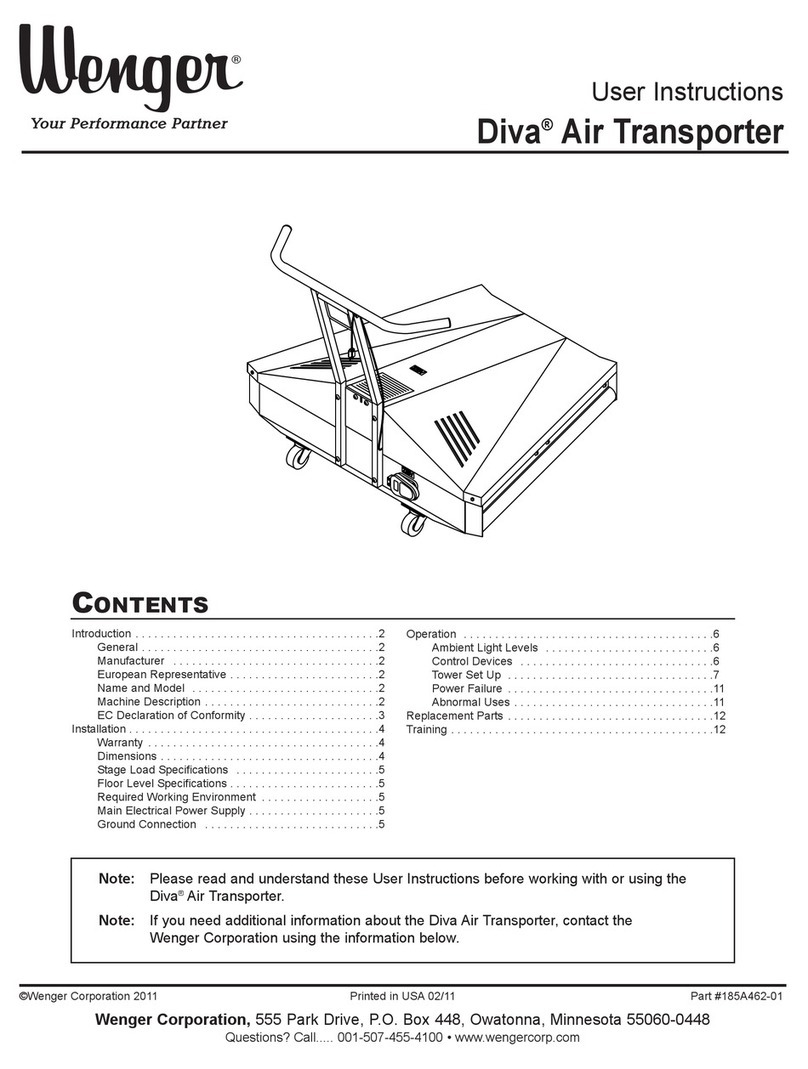
Wenger Diva 185E549 User manual

User Instructions
Diva
®
Air Transporter
©Wenger Corporation 2021 Printed in USA 2021-08 Part #185A462-02
Wenger Corporation, 555 Park Drive, P.O. Box 448, Owatonna, Minnesota 55060-0448
Questions? Call.....USA: (800) 4WENGER (493-6437) • Worldwide: +1-507-455-4100 • wengercorp.com
Introduction . . . . . . . . . . . . . . . . . . . . . . . . . . . . . . . . . . . . . . . . . . 2
General .........................................2
Manufacturer .....................................2
European Representative ...........................2
Name and Model..................................2
Machine Description ...............................2
EC Declaration of Conformity ........................3
Installation . . . . . . . . . . . . . . . . . . . . . . . . . . . . . . . . . . . . . . . . . . . 4
Warranty ........................................4
Dimensions ......................................4
Stage Load Specications...........................5
Floor Level Specications ...........................5
Required Working Environment ......................5
Main Electrical Power Supply ........................5
Ground Connection ................................5
Operation. . . . . . . . . . . . . . . . . . . . . . . . . . . . . . . . . . . . . . . . . . . . 6
Ambient Light Levels...............................6
Control Devices...................................6
Tower Set Up.....................................7
Power Failure ....................................11
Abnormal Uses ...................................11
Replacement Parts . . . . . . . . . . . . . . . . . . . . . . . . . . . . . . . . . . . . 11
Training . . . . . . . . . . . . . . . . . . . . . . . . . . . . . . . . . . . . . . . . . . . . . 11
Air Beam Replacement . . . . . . . . . . . . . . . . . . . . . . . . . . . . . . . . . 12
Check Size of the Air Beam .........................12
Remove Current Air Beam ..........................13
Attach New Air Beam ..............................15
Contents
Note: Please read and understand these instructions before using.
Note: If you need additional information, contact Wenger Corporation using the information below.
Visit the Diva Acoustical Shell web page at wengercorp.com for more information.

2
Important User Information
General
Copyright © 2021 by Wenger Corporation
All rights reserved. No part of the contents of this manual may be reproduced, copied, or transmitted in any form
or by any means including graphic, electronic, or mechanical methods or photocopying, recording, or information
storage and retrieval systems without the written permission of the publisher, unless it is for the purchaser's
personal use.
Printed and bound in the United States of America.
The information in this manual is subject to change without notice and does not represent a commitment on the
part of Wenger Corporation. Wenger Corporation does not assume any responsibility for any errors that may
appear in these instructions.
In no event will Wenger Corporation be liable for technical or editorial omissions made herein, nor for direct,
indirect, special, incidental, or consequential damages resulting from the use or defect of these instructions.
The manufacturer reserves the right to change this product at any time.
The information in this document is not intended to cover all possible conditions and situations that might occur.
The end user must exercise caution and common sense when assembling or installing Wenger Corporation
products. If any questions or problems arise, call the Wenger Corporation at (800) 4WENGER (493-6437)
or +1-507-455-4100 worldwide.
Manufacturer
The Diva®Air Transporter is manufactured by:
Wenger Corporation
555 Park Drive
Owatonna, MN 55060
(800) 4WENGER (493-6437) • +1 (507) 455-4100
wengercorp.com
European Representative
See the EC Declaration of Conformity for information about a European Representative.
Name and Model
Diva Air Transporter 230 volt.
Machine Description
A Diva Air Transporter is designed to receive acoustic towers. The machine is only intended to lift and
transport acoustic towers.
The operator loads and unloads a Diva Air Transporter manually. It requires a 230 VAC 50 or 60 Hz
single-phase 15 amp main electrical supply.
The air blower operates at a maximum pressure of 0.15 Bar (2.25 psig) at the maximum load and ow rate
of 1840 to 3681 liters/min (65 to 130 cubic feet/min).
Intended Use
• This product is intended for indoor use in normal ambient temperature and humidity conditions —
it must not be exposed to prolonged outside weather conditions.
• This product is intended to be used only as described in these instructions.
Warranty
This product is guaranteed free of defects in materials and workmanship for ve full years from date of
shipment. A full warranty statement is available upon request.

3
Important User Information (continued)
EC Declaration Of Conformity
Manufacturers Name: Wenger Corporation
Manufacturers' Address: 555 Park Drive, Owatonna, MN 55060 USA
Declare that the machinery described below complies with applicable health and safety requirements of Part 1
of Annex 1 of the Machinery Directive 98/37/EC taking full account of the additional requirements of Machinery
Directive 2006/42/EC and the EMC Directive. Condential technical documentation has been compiled in
accordance with Part A of Annex VII of Machinery Directive 2006/42/EC and is available to European national
authorities on written request only. If a request is received documentation will be transmitted by post.
Description: Diva Air Transporter 230 volt
Model Number: 185E549
Sizes: An Air Transporter is designed to receive acoustic towers varying in size from 4.8 m (192 inches) to
9.7 m (384 inches) high, 3 m (120 inches) to 3.6 m (144 inches) wide and length 1.4 m (56 inches)
deep weighing up to 885 Kg (1950 lbs). The machine is only intended to lift and transport acoustic
towers. The dierent types of acoustic tower that can be lifted and transported are identied in
operating instructions.
The following standards have either been referred to or been complied with in part or in full as relevant:
ENISO 12100 - 2 Machinery Safety - Basic concepts, general principles for design – Part 2: Technical
principles and specications
EN 954-1 Machinery Safety - Safety Related Parts of Control Systems – Part 1: General Principles for
Design
EN 811 Machinery Safety - Safety distances to prevent danger zones being reached by the lower limbs
EN 614 Machinery Safety - Ergonomic design principles
EN 953 Machinery Safety -General requirements for the design and construction of guards
EN 418 Machinery Safety - Emergency stop equipment, functional aspects. Principles for design
EN 60204-1 Machinery Safety - Electrical Equipment of Machines
EN61000-6-3:2001 EMC - Generic emissions standard
EN61000-6-1:2001 EMC - Generic susceptibility standard
Full Name of Responsible Person:……………………………………………………………….………..(Typed)
Position:…………………………………………..…..(Typed) Place of Signing:……………………….
Signature: …………………………………………… Date: ……………………………………
Full Name of Authorized European Representative:………………………………………………..…..(Typed)
Position:…………………………………………..…..(Typed) Place of Signing:……………………….
Signature: …………………………………………… Date: ……………………………………
Full Name of Authorized European Representative:…………………………………………….…..…..(Typed)
Position:…………………………………………..…..(Typed) Place of Signing:……………………….
Signature: …………………………………………… Date: …………………………………

4
Make sure that anyone working
with the air transporter has
read and understands these
instructions.
!WARNING
Always observe and comply
with the Warnings and
Cautions posted on the system
equipment.
!WARNING
Failure to comply with Warnings
and Cautions in this document
can result in damage to property
or serious injury.
!WARNING
Safety Precautions
Throughout this document you may nd cautions and warnings which are dened as follows:
• WARNING: Failure to follow the instruction could result in serious injury or damage to property.
• CAUTION: Failure to follow the instruction could result in minor injury or damage to property.
Read all of these safety instructions before using the equipment.
Installation
Dimensions
1105 mm
(43.5")
1270 mm
(50")
953 mm
(37.5")
(917 mm)
(36.1")

5
Installation (continued)
Stage Load Specications
An air transporter is designed to receive acoustic towers varying in size from
4877 to 9754 mm (16' to 32') high, 3048 to 3658 mm (10' to 12') wide, 1448 mm (4' 9") deep and weighing
up to 885 kg (1950 lb).
The machine is only intended to lift and transport Wenger Diva Acoustic Towers.
Floor Level Specications
An air transporter must only be used on level ground.
Required Working Environment
An air transporter is designed for use indoors in a normal working environment.
The intended operating temperature range is 7°C (45°F) to 35°C (95°F). It must only be used on level ground,
on a smooth solid oor with no ridges, holes or obstructions.
Main Electrical Power Supply
A power switch is provided to enable an air transporter
to be disconnected from the main electrical supply.
When the power switch is switched from the
OFF position to the ON position, the earth
connection is made before power connections
are made. When the power switch is switched
from the ON position to the OFF position, power
connections are broken before the earth connection
is broken. In the OFF position, the electrical power
supply is removed from the entire machine.
The electrical power supply is provided by
the use of a standard power cord.
The standard power cord must be routed
where there is no risk of personnel tripping and
falling because it has been routed in areas where
personnel are expected to walk. It is recommended
that cables should be routed away from such areas,
run in rubber ramps or the area cordoned o to
keep people away.
Ground Connection
The blower motor, electrical control box, and metalwork of the machine are bonded to earth (ground) to prevent
a build up of static electricity. This is necessary to ensure that there is no risk of an increase in the voltage
potential of the blower motor, electrical control box and metalwork of the machine as a result of static electricity
that might be generated.
The earth conductor in the incoming main power supply is connected to a protective earth terminal and one
cable taken from this terminal to an earth distribution connector block. Functional earth connections to the
blower motor, electrical control box, and metalwork of the machine, etc. are connected to the earth distribution
connector block.
Standard
Power Cord
Power
Switch

6
Operation
Ambient Light Levels
An air transporter is only intended for use inside buildings where there will be articial lighting.
Ambient lighting must be sucient for operators to see inside and around all parts of the machine.
There is no need to provide additional internal lighting under the hood. Maintenance personnel can see
all internal parts when access covers have been removed and there is no need to provide additional internal
lighting.
Local ambient lighting should achieve a light intensity of 300 LUX around the air transporter and in
the immediate vicinity of those parts of the machine where maintenance must be performed.
There are no exposed rotating parts on an air transporter that might put operators at risk if there are
stroboscopic eects due to lighting powered by a 50 or 60 Hz AC mains electrical supply.
This is because all rotating parts of an air transporter are behind plain metal panels or hoods.
Control Devices
The control device for raising and lowering the front caster is a foot activated mechanism. This is located
at the rear center of the base. Operators stand behind the handlebar of the machine where they are able to
see all parts of the machine while it is being maneuvered. A second person is needed to determine whether
there are other personnel who might be in the path of the machine. This makes it possible for operators to
safely maneuver acoustic towers.
The power switch is hand operated and located at the upper rear of the base shroud. In this position it is
easy to access and operate. There is no need for adjustment, the power switch is accessible to persons of
all heights. The power switch is a positive action on/o switch that has immediate feedback of being engaged
or disengaged. The device only provides lift and does not provide locomotion. One person can lift all heavy
items that need to be lifted for maintenance with ease. The machine does not determine the work rate because
the operator is not required to position acoustic towers onto the machine at a rate that is set by the machine.
Control devices are located at levels where tall and short operators have ease of access and where they are
in full view of the operator. The function of each control device and what it achieves is marked alongside each
control using characters that are typically 6 mm or more high. There is only one set of controls and no risk of a
second operator being able to control the machine using a second set of controls in conict with the rst.
Handlebar
Power
Switch
Control
Device

7
Operation (continued)
Tower Set Up
In normal operation, an air transporter can be maneuvered manually with ease once the air cushion
has been inated. There is little risk of fatigue by the operator. The force needed to push the assembly is
13.6 kg (30 lb) and this is not excessive. Acoustic towers weigh up to 885 kg (1950 lb) and are positioned
manually, with minimal physical eort.
While maneuvering the machine, two people are required. One person is needed to push the air transporter
while the second person is needed to ensure that the way is clear for an acoustic tower to be moved forward.
To assist operators, the acoustic towers are positioned simply by engaging lugs on the air transporter in the feet
of an acoustic tower. This enables tall and short operators to position the acoustic towers without the need to
reach or stoop and is not stressful.
Provided acoustic towers of the correct type are presented to the machine, there should be no handling
problems. Operating instructions provide instruction on how to attach acoustic towers to an air transporter and
how to check the security of acoustic towers so that they cannot come loose.
1. To move the air transporter when it is not supporting an acoustical tower, tilt the front end upward on the
rear casters about 10 to 15 degrees. The front caster will drop downward and lock into place.
Move the air transporter to the acoustic tower that is to be moved.
To move the air transporter when not
supporting a Tower, tilt the front end
upward about 10 to 15 degrees
Never use the air transporter for
any purpose other than to move
and position towers.
Never attempt to manually lift or
move a tower without using an
air transporter.
!CAUTION !CAUTION
Never move a tower on an
inclined surface or ramp.
!WARNING

8
Operation (continued)
Tower Set Up (continued)
2. Press inward in the caster release plate with the toe of
your shoe to disengage the caster lock and allow the
front of the air transporter to lower to the oor surface.
3. Position the air transporter under the tower with
the lifting hooks under the lifting brackets on both
sides of the tower.
Be sure that the extension cord is long enough
to reach wherever the air transporter will be
moved.
Prevent cord interference or damage by having
another person manage the cord while moving
the towers.
Lifting
Bracket
Lifting
Hook
Air
Transporter
Caster
Release Plate
Two or more people must
work together when moving
an acoustic tower.
One person must always
watch for obstructions on the
stage and above the stage
while a second person pushes
the air transporter.
Always clear all people
and objects from the stage
when moving acoustic
towers to or from storage.
When using the air transporter be
sure that all electrical connections
will not separate and interrupt power.
!CAUTION !CAUTION
!CAUTION

9
Operation (continued)
Tower Set Up (continued)
4. Turn on the air transporter air blower by turning on the power switch.
Note: Be sure that both lift hooks engage the lifting brackets.
5. Slowly pull the air transporter to move the acoustic tower approximately 1524 mm (5') out from the others.
6. Stop moving the acoustic tower so that a second person can make sure
that the wing panels are locked in the storage position and that the wing
doors are locked to the wing panels.
Always rotate and lock the tower wing panels
to the storage position before moving the
tower to or from the performance position.
!CAUTION
Never move a tower on an
inclined surface or ramp.
!WARNING
Always clear people and
objects from the stage
when moving a tower.
!WARNING
Power
Switch

10
Tower Set Up (continued)
7. With one person pushing the tower and a second person guiding, slowly move (no faster than 0.3 m [1 foot]
per second) the tower to the performance position.
Be careful to not push the tower into any obstructions on the stage oor or above the stage oor
(such as ceiling panels, etc.).
Note: It is best to create permanent marks for the nal
performance locations for all towers before moving
the them from storage.
8. When the tower is in the nal performance location,
turn o the air blower by turning o the power switch.
Note: As the air escapes from the air pads, the tower
will tilt slightly forward.
9. Remove the Diva Air Transporter from the acoustic tower
as follows.
a. When the air pads are deated, pull the air transporter
away from the acoustical tower until the lift hooks are
clear of the tower lift brackets.
b. Place a foot against the rear of the air transporter and
tilt the front upward until the front caster locks into place
(down position).
c. Move the air transporter to the next acoustical tower to
be moved.
10. Repeat these steps to move the remaining towers to their
performance positions.
Never move a tower faster than 0.3 m (1 foot) per
second. Moving an acoustic tower carelessly or
too fast can cause an accident such as tipping it
over or running into objects.
!CAUTION
Operation (continued)
Two or more people must work together when
moving a tower. One person must watch for
obstructions on the stage and above the stage
while a second person pushes the tower.
!CAUTION
A dangerous pinch point develops
when lowering a tower to the oor.
!CAUTION
Pull the air transporter clear of the
acoustic tower and tip front end
upward to deploy the front caster
(lock into the down position).

11
Power Failure
If there is a failure of the main electrical power supply, the air transporter ceases to operate.
When the main electrical power supply has been restored, power is returned to the air transporter and the air
cushions will inate. The air transporter only provides lift, and does not provide locomotion. There is therefore,
no risk of a air transporter moving unexpectedly following failure of the main electrical power supply.
Abnormal Uses
Examples of abnormal uses to which an air transporter should not be put. Wenger takes no responsibility for
the safety of machines if they are used for any purpose other than the intended purpose as specied in these
instructions.
● Crushing, impact or entrapment should an acoustic tower topple because an air transporter is used to
transport shells or other panels besides those prescribed.
● Crushing, impact, or entrapment as a result of failing to connect acoustic towers to the machine using a
suitable means of attachment.
● Crushing, impact or entrapment should an air transporter be used to lift and transport a heavy load other
than an acoustic tower and the machine fails structurally.
● Exposure to any hazards on the machine as a result of operating the machine under the inuence of drugs
or alcohol or while wearing loose clothing.
● Exposure to ying or ejected objects caused by using poor quality replacement parts that have been
obtained from an unauthorized source.
Operation (continued)
Never use the air transporter for
any purpose other than to move
and position towers.
When using the air transporter be
sure that all electrical connections
will not separate and interrupt power.
!CAUTION
!CAUTION
Replacement Parts
Should there be a need for replacement parts, contact Wenger at +1-507-455-4100.
Training
Training is provided at the time of installation.

12
Air Beam Replacement
The air beam on a diva air mover may need to be replaced if it has been torn or worn through.
Check Size of the Air Beam
1. Remove the new air beam from the package and make sure it's the same size as the damaged one being
replaced on the air mover.
Note: Feel through the fabric and measure the size of the wood backer.
2. If the new air beam is not the same size as the old one (within 13 mm [½"]), contact Wenger Corporation
before continuing.
Replacement
Air Beam
Current
Air Beam

13
Air Beam Replacement (continued)
Remove Current Air Beam
IMPORTANT: Keep all fasteners and clamps that are removed, they will be used to attach the new air beam.
1. Remove the air mover hood.
a. Remove the fasteners
(shoulder bolt, plastic spacer and lock nut)
from the front of both sides.
b. Carefully lift the hood o and set it aside.
2. Remove the hose clamp and disconnect the hose from the tee at the blower motor.
3. Remove the twelve screws that attach the air beam to the support plate.
Air
Beam
Air Mover
Hood
Plastic
Spacer
Shoulder
Bolt
Lock
Nut
Plastic
Spacer
Shoulder
Bolt
Lock
Nut
Screws
Support
Plate
Remove hose clamp
and disconnect hose
from tee
Plastic
Spacer
Shoulder
Bolt
Lock
Nut

14
Air Beam Replacement (continued)
Remove Current Air Beam (continued)
3. Tip the air mover back and pull the air beam and hose assembly away from the support plate.
4. Remove the hose/coupler and valves from the air beam.
IMPORTANT: The hose is glued to coupler and cannot be removed from the coupler.
The coupler must be removed from the original air beam and installed on the new air beam.
Screws
Remove air beam
and hose assembly
Hose and
Coupler
Inlet Valve
Flap Valve
Socket

15
Air Beam Replacement (continued)
Attach New Air Beam
1. Remove and discard any existing coupler from the new air beam.
2. Attach the ap valve, inlet valve, and hose/coupler to the new
air beam in the same order as they were removed. Secure in place
with the existing screws.
3. Feed the hose through the hole in the support plate
and position the air beam to be parallel to the support plate.
4. Tip the air mover upright.
Feed hose
through hole
279 ± 3 mm
(11" ± 0.125")
Outline
of board
178 ± 3 mm
(7" ± 0.125")
Screws
Hose and
Coupler
Inlet Valve
Flap Valve
Socket
Support
Plate

16
Air Beam Replacement (continued)
Attach New Air Beam (continued)
4. Attach the air beam to the support plate using the original twelve screws according to these measurements.
5. Connect the hose to the tee at the blower motor and attach it using the original hose clamp.
6. Replace the air mover hood using the original fasteners.
74 ± 3 mm
(2.906" ± 0.125")
from board edge
Air
Beam
Screws
Support
Plate
Connect hose to
tee and attach hose
clamp
114 ± 3 mm
(4.5" ± 0.125")
from board edge
Table of contents
Other Wenger Farm Equipment manuals
Popular Farm Equipment manuals by other brands

Kerbl
Kerbl 70552 User information

KIRLOSKAR
KIRLOSKAR KMW Univator Operator's and service manual

Tru-Test
Tru-Test MilkHub Application Instructions

MacDon
MacDon PW8 Unloading and assembly instructions

GREAT PLAINS
GREAT PLAINS Yield-Pro 3P3025AH installation instructions

JF
JF JF 2D Operation & technical manual