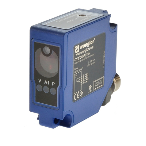
Wenglor OY2TA104P0150C User manual

EN
OY2TA104P0150C
High-Performance Distance Sensor
Operating Instructions
Translation of the Original Operating Instruction
Subject to change without notice
Available as PDF version only
Status: 01.08.2019
wenglor.com

2
EN
Index
1. Proper Use 4
2. Safety Precautions 4
2.1. Safety Precautions 4
2.2. Laser/LED warning 4
2.3. Approvals and IP Protection 4
3. Technical Data 5
3.1. Connecting the Sensors 6
3.2. Housing Dimensions 7
3.3. Control Panel 8
3.4. Complementary Products 9
4. Mounting Instructions 9
5. Initial Operation 10
5.1. Operation on a controller 10
5.2. Default Settings 10
6. Functional Overview OLED-Display 11
6.1. Run 13
6.2. Display 13
6.2.1. Display Mode 13
6.2.2. Display Intensity 14
6.3. Filter 14
6.4. Output Rate 14
6.5. Laser 15
6.6. I/O Test 15
6.7. Network 16
6.8. Language 16
6.9. Info 16
6.10. Reset 17
6.11. Password 17
7. Information on EtherCAT 18
8. Web-based configuration 21

4
EN
1. Proper Use
This wenglor product has to be used according to the following functional principle:
High-Performance Distance Sensors
High-performance distance sensors which use the principle of transit time measurement determine the dis-
tance between the sensor and the object according to the principle of transit time measurement. These sensors
have a large working range and are therefore able to detect objects over large distances.
Selected sensors are distinguished by WinTec (wenglor interference free technology). This technology allows
black or shiny surfaces to be reliably detected even in extremely inclined positions. It is possible to mount sev-
eral sensors next to or across from each other without them influencing each other.
2. Safety Precautions
2.1. Safety Precautions
• This operating instruction is part of the product and must be kept during its entire service life.
• Read this operating instruction carefully before using the product.
• Installation, start-up and maintenance of this product has only to be carried out by trained personal.
• Tampering with or modifying the product is not permissible.
• Protect the product against contamination during start-up.
• These products are not suited for safety applications.
2.2. Laser/LED warning
Class Laser 1 (EN 60825-1)
Observe all applicable standards
and safety precautions.
2.3. Approvals and IP Protection
RoHS
LASER CLASS 1
EN 60825-1:2014

5
3. Technical Data
Order Number OY2TA104P0150C
Working Range 0,1...10,1 m
Linearity Deviation 20 mm
Reproducibility 7 mm
Light Source Laser (red)
Output Rate 330/s
Wave Length 660 nm
Service Life (Tu = 25 °C) 100000 h
Max. Ambient Light 5000 Lux
Laser Class (EN 60825-1) 1
Beam Divergence < 2 mrad
Light Spot Diameter see table 1
Port Type 100BASE-TX
PoE Class 1
Response Time < 10 ms
Temperature Range –25...50 °C
Reverse Polarity Protection yes
Protection Class III
Adjustment Menu (OLED)
Housing Plastic
Degree of Protection IP68
Connection M12×1, 8-pin
Webserver yes
EoE (Ethernet over EtherCAT)
Control Panel No. X2, T10
Interface EtherCAT
Light Spot Diameter
Working Distance 0 10 m
Light Spot Diameter 5 mm < 20 mm
Table 1

6
EN
3.1. Connecting the Sensors
OY2TA104P0150C
001
Legend
Wire Colors according to IEC 60757
Platinum measuring resistor
not connected
Test Input
Test Input inverted
Trigger Input
Ground for the Trigger Input
Analog Output
Ground for the Analog Output
Block Discharge
Valve Output
Valve Control Output +
Valve Control Output 0 V
Synchronization
Ground for the Synchronization
Receiver-Line
Emitter-Line
Grounding
Switching Distance Reduction
Ethernet Receive Path
Ethernet Send Path
Interfaces-Bus A(+)/B(–)
Emitted Light disengageable
Magnet activation
Input confirmation
Contactor Monitoring
Black
Brown
Red
Orange
Yellow
Green
Blue
Violet
Grey
White
Pink
Green/Yellow
Supply Voltage +
Supply Voltage 0 V
Supply Voltage (AC Voltage)
Switching Output (NO)
Switching Output (NC)
Contamination/Error Output (NO)
Contamination/Error Output (NC)
Input (analog or digital)
Teach Input
Time Delay (activation)
Shielding
Interface Receive Path
Interface Send Path
Ready
Ground
Clock
Output/Input programmable
Power over Ethernet
Safety Input
Safety Output
Signal Output
Ethernet Gigabit bidirect. data line (A-D)
Encoder 0-pulse 0-0 (TTL)
Encoder A/A (TTL)
Encoder B/B (TTL)
Encoder A
Encoder B
Digital output MIN
Digital output MAX
Digital output OK
Synchronization In
Synchronization OUT
Brightness output
Maintenance
reserved
PT

7
3.2. Housing Dimensions
1 = Transmitter Diode
2 = Receiver Diode

8
EN
3.3. Control Panel
X2
85
84
78
T12
20 = Enter Button
22 = Up Button
23 = Down Button
60 = Display
78 = Module Status
84 = Communication Status
85 = Link/Act LED
Designation Condition Function
Status
Green off ESM state: Initialisation
Green flashing ESM state: PRE - Operational
Flashing green once ESM state: SAFE - Operational
Green on ESM state: Operational
Red off No Error
Red on Application controller failure
Flashing red once Local Error
Flashing red twice Process Data Watchdog Timeout/
EtherCAT Watchdog Timeout
Red flashing Red blinking Invalid Configuration
MS (Module Status)
Off —
Green Operate Status
Red Device Error
Red flashing —
L/A
Off No Ethernet device has been connected to the port.
Green An Ethernet device is connected to the port.
Green flashing An Ethernet device is connected to the port and is
currently communicating.

9
3.4. Complementary Products
wenglor offers Connection Technology for field wiring.
Suiting Mounting Technology No.
340
Suiting Connection
Technology No.
50
S81
Protection Housing Set ZST-NN-02
Midspan Adapter Z0029
Switch with PoE ZAC50xN0x
4. Mounting Instructions
When using the Sensor, follow the corresponding electrical and mechanical regulations, standards and safety
rules. The Sensor must be protected against mechanical influence. The Sensor has optimum extraneous light
qualities when the background is within the working range.

10
EN
5. Initial Operation
5.1. Operation on a controller
If you want to place the device into service at a controller, please complete the following steps:
• Connect the Sensor to a switch with PoE using an appropriate cable M12×1; 8-pole. In the case of a switch
without PoE, please use the Midspan Adapter (Z0029) for the appropriate voltage supply. When the voltage
supply is present, the display on the Sensor starts.
• You will need the EtherCAT XML Device Description File (ESI-File EtherCAT Slave Infor-
mation) which is available at www.wenglor.com Product World Product search
(Enter the product number) Download Product Description Files.
• The files should always be stored in the ESI directory of the respective master. If the Twin-CAT software is
used, it should be stored in the folder “...\IO\EtherCAT\” in the installation folder.
• The following example shows the steps that have to be carried out (example based on the TwinCat System
Manager by Beckhoff):
• First, the list “Echtzeit Ethernet kompatible Geräte” (list of all real-time Ethernet-compatible devices) must be
requested.
• Once the correct network card has been installed, new slave devices can be searched for in “E/A Geräte” (I/O
devices). If all configurations are correct, the slave devices are now listed in the TwinCAT tree.
• The assemblies can now be switched into “Free Run” mode so that the local cycle runs independently of the
pre-set master cycle.
• In the next step, the process data of the individual devices can be configured.
For a more detailed description of the different control systems and the installation of files or the network de-
sign, please refer to the help files of the corresponding control system.
5.2. Default Settings
OCPxxxP0150P
Display Mode Process
Intensity Screensaver
Filter 1
Output Rate Normal
Laser ON
Network
IP-Address 192.168.100.1
Subnet Mask 255.255.255.0
DHCP DHCP OFF
Std Gateway 192.168.100.254
MAC Address (See type plate on the product)
Language English
Password Activate Off
Change 0
11
6. Functional Overview OLED-Display
Deutsch
English
Français
Español
Italiano
Press <R>
for Reset
Display of Part
number and
Sensor version
ON, OFF
Password: 0 – 9999
Run Mode
Enable
Change
Lock
Language
Info
Reset
Password
Run
Min
Medium
Max
Power save
Screensaver
Process
Text
Analyse
Network
Mode
Rotate
Intensity
Display
Filter
1 10 100
2 20
5 50
Laser On
Off
E/A Test
Value in µm
No. of Status Bit
OK
Warmup
OK
Too low
Too high
Measured Value
Status Bits
Warmup
Signal
Temperature
Output Rate Normal
Fast
Run Mode
Network
IP address
Subnet Mask
Std Gateway

12
EN
Fig. 1: Set language menu
Navigation by pressing the button:
5 : Navigation up.
6 : Navigation down.
: Enter Button.
The selection is confirmed by pressing the Enter button.
Meaning of the menu items:
3Back : one level higher in the menu.
7Run : Switch to display mode.
Change to the configuration menu by pressing any button.
Note: If no setting is made in the configuration menu for a period of 30 s, the Sensor returns automatically to
the display view.
Pressing the button again returns the Sensor to the last menu view used. If a setting is made, it becomes active
once you leave the configuration menu.
Important: To prevent any damage to the buttons, please do not use any pointed objects for setting.
The following explains the functions behind the individual menu items.

13
6.1. Run
The Sensor switches into display mode.
EtherCAT device name
Current measured value in mm
Bar graph display of the current
measured value relative to the
measuring range
Status LEDs
Symbol descriptions of status LEDs:
Symbol Significance State 1 State 2 State 3
Symbol 1 Warm-up ok wait –
Symbol 2 Signal Strength ok too low
(dirty) too high
Symbol 3 Temperature ok too high too low
6.2. Display
Display Adjust the display device
Mode
Rotate
Intensity
3Back
7Run
Mode: Select display mode (see chapter 7.2.1)
Rotate: Rotate display by 180°. By pressing the “” button the display is rotated
by 180°. The rotation is canceled by pressing this button again.
Intensity: Set the display intensity (see chapter 7.2.2)
6.2.1. Display Mode
The measured value in mm and the order number always appear at the sensor’s display. Selection can be
made amongst the following additional displays using the “Display Mode” menu option:
Mode Adjust the display device
Process
Text
Analysis
Network
Process: Display of status LEDs for warm-up, signal strength and temperature.
Text: Display of a free text that can be sent to the Sensor via the control.
Analysis: Display of signal strength in percent and measuring rate in 1/s.
Network: Display of the EtherCAT LEDs MS, CS and L/A. For the function of these
LEDs, see “4.3. Control Panel” on page 8.

14
EN
6.2.2. Display Intensity
Intensity Set the display intensity
Min
Normal
Max
Power save
Screensaver
Min: The intensity of the display is set to a minimum value.
Normal: The intensity of the display is set to a medium value.
Max: The intensity of the display is set to a maximum value.
Power save: The display switches off after one minute without a button being
pressed and automatically switches back on when a button is
pressed.
Screensaver: The colors of the display are inverted every minute.
6.3. Filter
The filter (filter size) is the number of measured values over which the Sensor takes an average. The larger the
filter selected, the slower the response time of the Sensor becomes when there is a change in the measured
values. A larger filter improves the reproducibility of the Sensor.
Filter Number of values for averaging
1
2
5
10
20
50
100
3Back
7Run
If 1 is selected, each measured value is output directly without averaging. When-
ever a value greater than 1 is selected, the Sensor takes an average over the
selected number of x measured values.
6.4. Output Rate
The output rate indicates how often the measured value is refreshed per second at the output.
Output Rate Adjust Output Rate
Normal
Fast
3Back
7Run
Normal: The normal output rate is 100/s.
This means that a new measured value is read out every 10 ms.
Fast : The fast output rate is 330/s.
This means that a new measured value is read out every 3 ms.
Note: If this mode is activated, the OLED display is switched off
as soon as a PROFINET controller goes online. It’s switch back on
automatically when the controller goes offline again.

15
6.5. Laser
In the menu item “Laser”, the emitted light can be switched on or off.
Laser Switch transmitted light on or off
On
Off
3Back
7Run
ON: Switch transmitted light on
OFF: Switch transmitted light off; the Sensor no longer supplies mea-
sured values
6.6. I/O Test
This function manually changes the output of the Sensor. As a result, it possible to test whether the further pro-
cess is working as desired. The test is automatically terminated once you leave the test menu.
I/O Test Test of the Sensor outputs
Measured value
Statusbits
Warm-up
Signal Strength
Temperature
3Back
7Run
Measured value: Default of a measured value in µm
Statusbits: The number of the status bit to be set can be selected by
pressing the “+” or “–” button. (see list of Statusbits)
Warm-up: Default of the warm-up on “ok” or “warm-up”
Signal strength: Default of the signal strength on “ok”, “too low” or “too high”
Temperature: Default of the temperature on “ok”, “too low” or “too high”
List of status bits:
Number Function Description of when the bit is set Measured value read-
out
1 General error One of the following bits is set. —
2Distance to object too
small
The current measured value is below the
working range.
Measuring range lower
limit
3Distance to object too
large
The current measured value is above the
working range.
Measuring range upper
limit
4 No signal The sensor does not detect an object
within its working range.
Measuring range upper
limit
5 Signal too weak Too little light is reflected back to the sen-
sor from the object (e.g. very dark surface).
The quality of the measured value is re-
duced as a result.
Current measured value
6 Signal too strong Too much light is reflected back to the
sensor from the object (e.g. reflector) The
quality of the measured value is reduced
as a result.
Current measured value
7 Warm-up procedure The sensor is currently in the warm-up
phase and the quality of the measured
value does not yet comply with the speci-
fied technical data. See page 5 below.
Current measured value

16
EN
8 Temperature too high The sensor is at the upper limit of its tem-
perature range. If temperature continues to
rise, the sensor may be destroyed.
Current measured value
9 Temperature too low The sensor is at the lower limit of its tem-
perature range. If temperature continues to
drop, the sensor may be destroyed.
Current measured value
6.7. Network
Network Settings of the Network Parameters
IP-Address
Subnet Mask
DHCP
Std Gateway
MAC Address
Net Reset
3Back
7Run
IP-Address: Display of the set IP-Address
Subnet Mask: Display of the set Subnet Mask
DHCP: Display DHCP ON or DHCP OFF
Std Gateway: Display of the set standard gateway
MAC Address: Display of the default MAC Address
Net Reset: Reset network settings to the default settings
6.8. Language
The menu language can be changed in the menu item “Language”. The user is automatically prompted for his
desired language at initial operation and after each reset.
Language Set menu language
Deutsch
English
Francais
Espanol
Italiano
3Back
7Run
The menu appears in the selected language immediately after selection.
6.9. Info
In the menu item “Info” the following information about the Sensor is displayed:
Info
Order number
Software version
Serial number

17
6.10. Reset
All Sensor settings, with the exception of the network settings, can be reset to the default settings in the menu
item "Reset. The settings of the default settings can be found in Chapter “6.2. Default Settings” on page 10.
Reset Reset to the default settings
Press <R> for Reset The Sensor settings that have been made can be reset to the default settings by
pressing the “R” button.
6.11. Password
Password protection prevents against changing the set data unintentionally.
Password Set password functionality
Activate
Change
Block
3Back
7Run
Enable: Turn password protection on or off. If password protection is acti-
vated, the operation of the Sensor is disabled after supply power
has been interrupted and is only enabled after successfully entering
password.
Change: Change password.
Lock: Locking Sensor causes an immediate disabling of operation if activate
Password is set to “on”.
If the password functionality is activated, the password must be entered before each operation of the Sensor.
After correctly entering the password by means of the “+” and “–” button, the menu is activated and the Sen-
sor is operational.
• The password functionality is deactivated in the default settings.
• The value range of the password number ranges from 0000…9999
It is necessary to note the newly defined code before changing the password. A forgotten password can
only be overwritten by a general password. The general password can be requested by sending an e-mail to
support@wenglor.com.

18
EN
7. Information on EtherCAT
You can find the ESI file for download at www.wenglor.com Product World Product search (Enter the
product number) Download.
Index Sub
index Name Data Type Access
right
PDO
mapped Default Settings Value
range Description
1000h 00h Device type Unsigned 32 Ro No 00000191h
1008h 00h Device name STRING Ro No OCPxxxP0150C 12 character
1009h 00h Hardware version STRING Ro No V1.0.0 6 character
100Ah 00h Software version STRING Ro No V1.0.5 6 character
1010h
Store parameters
00h Highest subindex
supported Unsigned 8 Ro No 1 1
01h Store all parameters Unsigned 32 Rw No 0
65766173h = store
any other = don‘t
store
1011h
Restore default parameters
00h Highest subindex
supported Unsigned 8 Ro No 1 1
01h Restore all parameters Unsigned 32 Rw No 0
64616F6Ch = restore
any other = don‘t
rest.
1018h
Identity Object
00h Highest subindex
supported Unsigned 8 Ro No 4 4
01h Vendor ID Unsigned 32 Ro No 0000059Bh
02h Product code Unsigned 32 Ro No 02011D0xh
OCP662P0150C
OCP352P0150C
OCP162P0150C
OCP801P0150C
03h Revision number Unsigned 32 Ro No 01000500h
04h Serial number Unsigned 32 Ro No nnnnnnnnh
10F8h Local time stamp Unsigned 64 Ro Optional
1600h
RxPDO
00h Highest subindex
supported Unsigned 8
W in
PreOp, R
in Op
0 0 …7 objects
1A00h
TxPDO
00h Highest subindex
supported Unsigned 8
W in
PreOp, R
in Op
2 2 …4 objects
01h SubIndex 001 Unsigned 32
W in
PreOp, R
in Op
21300020h
02h SubIndex 002 Unsigned 32
W in
PreOp, R
in Op
24270010h
1C00h Sync manager type

19
1C12h
RxPDO assign
00h Highest subindex
supported Unsigned 8
W in
PreOp, R
in Op
No 1 0 … 1
01h SubIndex 001 Unsigned 16
W in
PreOp, R
in Op
No 1600h
1C13h
TxPDO assign
00h Highest subindex
supported Unsigned 8
W in
PreOp, R
in Op
No 1 1
01h Subindex 001 Unsigned 16
W in
PreOp, R
in Op
No 1A00h
1C32h SM output parameter
1C33h SM input parameter
2040h
Device Access
00h Highest subindex
supported Unsigned 8 Ro No 2 0 – 254 2
01h Webserver Access BOOL Rw No 0: Enabled 0 – 1
0: Enabled
1: Disabled
02h Key disabling BOOL Rw No 0: Enabled 0 – 1
0: Enabled
1: Disabled
2100h
Display settings
00h Highest subindex
supported Unsigned 8 Ro No 5 0 – 254 5
01h Display mode Unsigned 8 Rw No 0: Process 0 – 3
0: Process
1: Analysis
2: Text
3: Network
02h Rotate display BOOL Rw No 0: Not rotated 0 – 1
0: Not rotated
1: Rotated
03h Display intensity Unsigned 8 Rw No 4: Screensaver 0 – 4
0: Minimum
1: Normal
2: Maximum
3: Energy saving
mode
4: Screensaver
04h Display language Unsigned 8 Rw No 1: English 0 – 4
0: Deutsch
1: English
2: Français
3: Español
4: Italiano
05h Display text STRING Rw Optional - Displayable text
18 characters

20
EN
2110h
Measured value settings
00h Highest subindex
supported Unsigned 8 Ro No 6 0 – 254 6
01h Laser ON-OFF Unsigned 8 Rw Optional 0: Laser ON 0 – 1 0: Laser On
1: Laser Off
02h Output rate Unsigned 8 Rw Optional 0: normal 0 – 1
0: Normal
1: Fast
03h Filter value Unsigned 8 Rw Optional 0: Filter size 1 0 – 6
0: Filter size 1
1: Filter size 2
2: Filter size 5
3: Filter size 10
4: Filter size 20
5: Filter size 50
6: Filter size 100
2130h 00h Measured value Unsigned 32 Ro Yes Distance value
2427h 00h Status Unsigned 16 Ro Yes
1: General
2: Object distance
too small
3: Object distance
too great
4: No signal
5: Contamination
6: Signal too high
7: Warm-up
procedure
8: Over-temperature
9: Under-temperature
8000h 00h
Measured
value timestamp
Unsigned 64 Ro Optional FFFFFFFFFFFFFFFFh
2990h
InternalObj2
00h Highest subindex
supported Unsigned 8 Rw No 2 0 – 254
01h SubIdx1 Unsigned 8 Ro No Internal use
02h SubIdx2 ARRAY Rw No Internal use
6131h
Physical unit
00h Highest subindex
supported Unsigned 8 Ro No 1 0 – 254
01h AI Instance 1 Unsigned 32 Ro No FD010000h
This manual suits for next models
1
Table of contents
Other Wenglor Analytical Instrument manuals
Popular Analytical Instrument manuals by other brands

Bühler technologies
Bühler technologies GAS 222.31 Ex1 Installation and operation instruction

Ricoh
Ricoh SC-20 manual

Keysight
Keysight N5224B PNA Installation notes

Stabila
Stabila Laser Distancer LD 320 user manual

Vivax Metrotech
Vivax Metrotech vLoc3 RTK-Pro Quick setup guide

geo-FENNEL
geo-FENNEL GeoDist 100 user manual