QUICK STARTGUIDE 5 of 6
BReset Procedures
Master Reset
(Used if the Master Code is unknown, if the Latch Code is unknown and the unit is in Latch
Mode, or if the Sleep Code is unknown and the unit is in Sleep Mode. All other codes will be
retained after completing this procedure.)
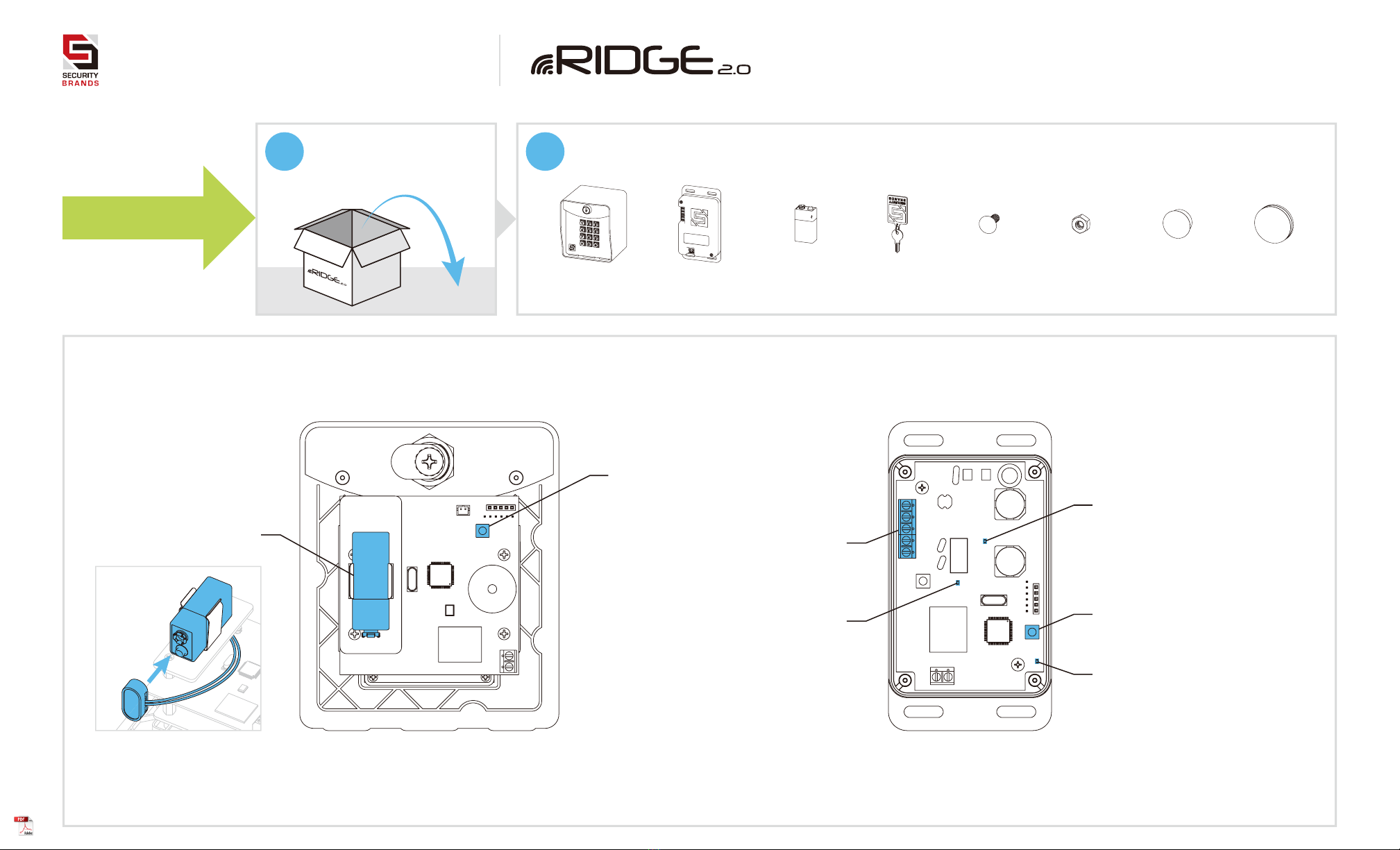
Step 1 - Remove front panel of keypad unit.
Step 2 - Disconnect battery.
Step 3 - Press and hold Reset Button; reconnect battery; then release Reset Button.
Unit will sound one (1) tone. Release Reset Button after you hear tone.
Step 4 - Press Star key (*) on keypad three (3) times and wait up to 30 seconds.
Step 5 - Reattach front panel onto keypad unit.
The Master Code is now reset to default ( 1251).
NOTE: If an error is made during these procedures, an “error” tone will sound and
you must start again from the beginning.
Unit Reset
(Used to reset unit to factory default settings. The Master Code will be retained.)
CAUTION: FOLLOWING THIS PROCEDURE WILL DELETE ALL CODES BUT MASTER CODE!
Step 1 - Remove front panel of keypad unit.
Step 2 - Disconnect battery.
Step 3 - Press and hold Reset Button; reconnect battery; then release Reset Button.
Unit will sound one (1) tone. Release Reset Button after you hear tone.
Step 4 - Enter Pound (#) Star (*) Pound (#) on keypad. (Unit will sound “good” tone.)
Step 5 - Enter 1251 (Master Code) on keypad. (Unit will beep continuously.)
Step 6 - While unit is beeping, disconnect and reconnect battery.
Unit will then go through power-up procedure.
Step 7 - Reattach front panel onto keypad unit.
The unit is now reset to factory default settings. Follow Master Reset to reset Master Code.
1
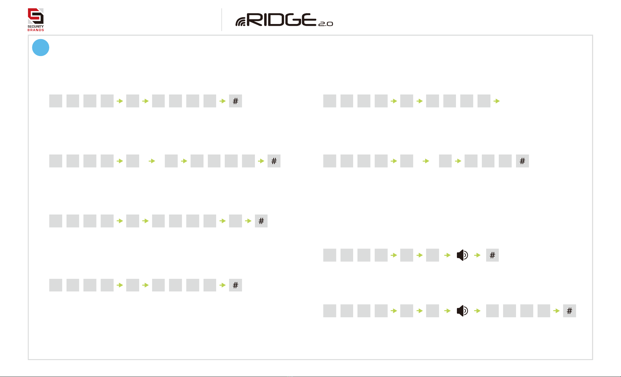
Programming Sub Modes
Add Access Code(s) to Channel A
7Add Access Code(s) to Channel B
9Pairing and Setting Keypad ID
8Add One-Time-Use Code (Channel A)
0Delete All Codes
2Delete Code(s)
3Change Master Code
4Configure “Three Strikes, You’re Out”
5Add Latch Code
6Set Relay Output Time
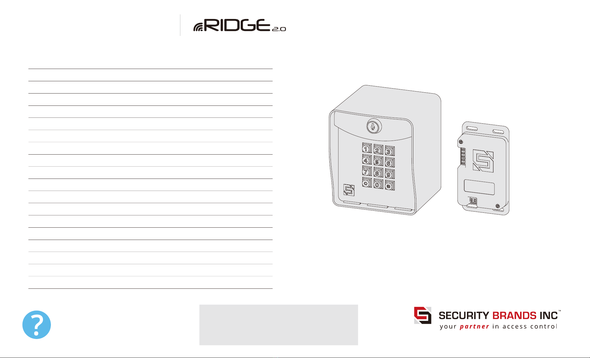
Things to Know
The Star Key (*)
The star key deletes your current entry.
If you happen to make a mistake keying in a code, simply
press the star key to delete the entire entry and start over.
The Pound Key (#)
The pound key is good for one thing and one thing only:
exiting Programming Mode. Whenever you’re in
Programming Mode, simply press the pound key to get out.
Reset Procedures
If for some reason the Master Code is forgotten or the unit
needs to be reset to factory defaults, two reset procedures
are available: Master Reset and Unit Reset .
These procedures can be found in Section B .
Model 14-500T