3
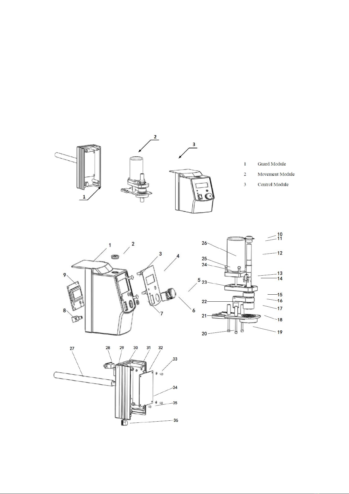
1 Front Guard 2 Rubber Cap 3 Nail 4 Membrane
5 Knob 6 Power Switch 7 Knob Lock 8 Knob Switch
9 Master Control Board
10 Coded Disc 11 Rubber Ring 12 Shaft
13 Photoelectric switch
14 M3*10 Socket Hexagon Screw 15 Bearing
16 Belt
17 Spindle Pulley 18 Bearing 19 M4*35 Socket Hexagon Screw
20 Ø 4 Elastic Pad 21 Lower Support Plate
22 Motor Pulley 23 Motor Bearing Support
24 M4*15 Socket Hexagon Screw 25Ø 4 Elastic Pad 26 Motor
27 Rail 28 RS232 Interface 29 M5*16 Socket Hexagon Screw
30 Rear Guard 31 M3 Hexagon Nut 32 M3*6 Copper Stud 33 Ø Ceramic Gaskets
34 Driven Board 35 M3*6 Pan Head Screw 36 Power Outlet
Fig. 4 illustrates the structural components of OS40 (20)-Pro, and Fig. 5 is the Exploded View of
OS40 (20)-Pro. Guard module includes front guard, Membrane, knob, power switch, rubber cap,
LCD PCB, knob switch, and PCB clamp and so on. Control modules are consisted of rear guard,
Driven Board, power outlet, RS232 interface and bar and so on. The movement module is
composed of motor, coded disc, shaft, motor pulley, bearing pulley, bearing, belt, photoelectric
switch, lower support plate and so on.
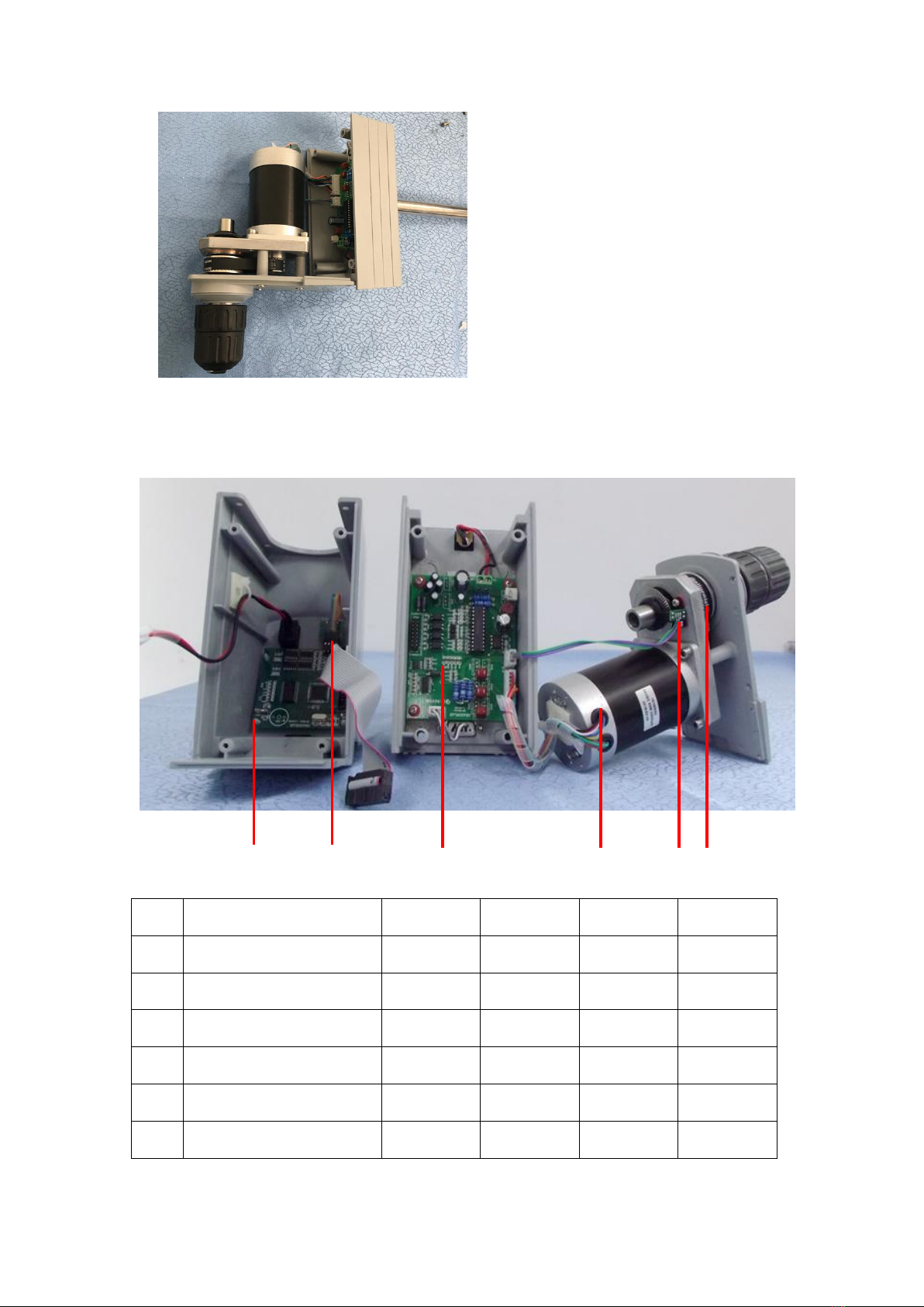
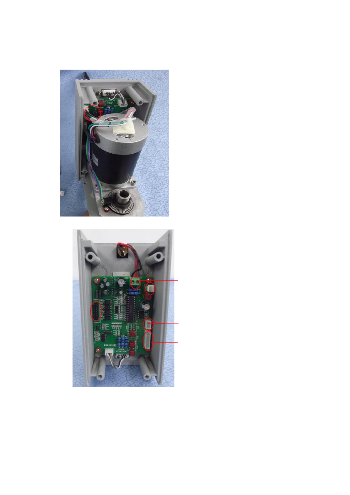
Stirring: Motor drives shaft to rotate though pulley, and further the shaft drives stirring
impeller fixed on it to rotate. Thus, the target sample is stirred.
Speed feedback: the motor speed is accurately measured by the coded disc fixed on the Shaft
along with photoelectric switch and a feedback is given. (OS40(20)-Pro)
LCD display: LCD PCB is connected to Driven Board and displays user’s settings and current
equipment operation information.(OS40(20)-Pro)
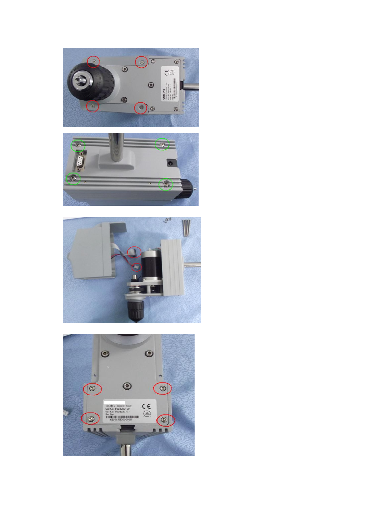
Chapter 2: Removal and Installation of Instrument
When instrument failure occurs, first, you should conduct a failure analysis; if the failure is caused
by the damage of instrument hardware, the related component must be repaired or replaced. Here
are the relevant contents of the replacement and disassembly of instrument.
2.1 Removal
Tool:Cross screwdriver