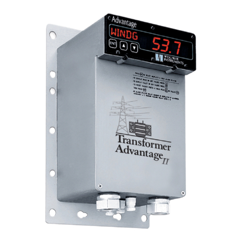
weschler instruments Transformer Advantage CT User manual

Transformer Advantage CT
Owners Manual
Manual Part Number OMG4T200
Revision 1, October, 2004
Use with Revision 02 of Firmware G4T02 and G4T03
16900 FOLTZ PARKWAY, CLEVELAND, OHIO 44149

Table of Contents
Section Title Section Page
Introduction .............................................................. 1.0 ..............................1
Description, Models and Features
Intended Usage, Feature and Module Locations
Receipt Inspection ........................................................ 2.0 ..............................3
Unpacking
Installation ............................................................... 3.0 ..............................4
Internal Inspection, Terminal - by - Terminal Connection Guide,
Power Requirements, Jumper Settings, Calibration Check,
Surface Mounting, Through-Panel Mounting, Channel Assignment,
High Potential and Insulation Resistance Testing, Terminal
Assignments, Relay Module Configurations
Operation ................................................................ 4.0 ............................. 19
Walk-up Functions, Operator Mode, Keystroke Diagrams
Sensor and Internal Alarm Displays
Configuration ............................................................. 5.0 ............................. 23
Supervisory Setup, Keystroke Diagrams, Keystroke - by - Keystroke
Set up Guide, Alarm Conventions and Function
Calibration ............................................................... 6.0 ............................. 42
CT and Linearization Table Calibration, Current Memory
and MCAR Calibration
Troubleshooting .......................................................... 7.0 ............................. 47
Digital Communications, Alarm Displays
Specifications ............................................................ 8.0 ............................. 49
Warranty .................................................................................................. 54
Figures 1. Feature and Module Locations (Surface mounting) .....................................................2
2. Feature and Module Locations (Through-Panel mounting) ................................................3
3. Power Supply and I/O Module Fuse and Jumper Locations .............................................5-6
4. Power and I/O Circuit EMI Protection...............................................................13-14
5. Terminal Assignments and Locations ..............................................................15-16
6. Relay Contact State Diagrams ....................................................................17-18
7. Walk-up Menu Keystroke Diagram .................................................................. 20
8. Sensor and Internal Failure Alarm Displays ........................................................... 21
9. Operator Loop Keystroke Diagram ................................................................. 22
10. Configuration Loop Entry Keystroke Diagram ........................................................ 24
11. Main Configuration Loop Summary Keystroke Diagram ................................................ 25
12. Main Configuration Loop Detail Keystroke Diagram (Figures 12A through 12D) ...........................26-29
13. Communications Port 1 Cabling ................................................................... 50
14. Surface Mount Outline and Drilling ................................................................. 50
15. Recommended Surface Mounting Methods ......................................................... 51
16. Prohibited Surface Mounting Methods .............................................................. 52
17. Through-Panel Mount Outline and Drilling ........................................................... 53
Tables 1. Fuse Ratings and Sizes ...........................................................................5
2. Summary of Field Configurable jumpers ..............................................................5
3. Platinum RTD Temperature - Resistance Equivalence ................................................. 46
4. Specifications ................................................................................... 49

OMG4T200 Rev 1 Page 1 of 54
1.0 Introduction
Description
The Transformer Advantage CT is a compact, fully electronic,programmable instrument designedfor accurate
and reliable thermalmanagement of liquidimmersedpower anddistributiontransformers.The computing engine
inthis implementation is based on the Motorola ColdFire microprocessor. The CX monitors the temperature of
the top oil and load current and calculates the temperature of the windings. Calculations of the winding
temperature use several key user-configurable transformer parameters and aproprietary algorithm based on
concepts contained in world recognized transformer standards.
The enclosure and electrical components of the Advantage are designed to withstand the harshest operating
environment. The electronics have been designed to continue functioning under extreme EMI/RFI conditions,
including close proximity walkie-talkie keying and near lightning strike.Their performance has beendocumented
through testing to world recognized EMC standards.
Major Features
iHigh accuracy 22 bit, 8 channel A/D conversion. Resolvable Accuracy ± 0.1 Degrees or 1 Amp.
iWinding Temperature Algorithm based on IEEE and IEC transformer concepts.
iOptional DNP-3 Slave Level 1 Communications Protocol.
iFirmware is Upgraded by Simple Upload of an Electronic File Through Digital Communications.
iTime Stamped Peak and Valley Values. History is downloaded via Digital Communications.
iReal Time Clock Power Back-up Five Days Standard, Thirty Days Optional.
i3 Button Front Panel Programming. No Covers to Open.
iWalk-up Selectable Display of Five Operating Measurements and Alarm Annunciators.
iAlpha-Numeric Displays for Prompts/Units and Values make Indications Clear and Non-confusing.
iUser-Entered Transformer Parameters for On-Site Custom Tailoring of Thermal Profiles.
iStandard Cooling Control Module with 5 Form B and 1 Form C High Capacity Set Point Relays.
iOptional Cooling Control Module with 4 Form C High Capacity Relays for Assignment Flexibility.
iTwo Cooling Control Modules Can be Combined to Provide 5 Form B and 5 Form C, or 8 Form C Relays.
i1 Optional High Capacity Auxiliary Set Point Relay for Logic or Alarm Functions.
iRelays are Independently Assignable to Eight Sources and a Remote Digital Command.
iRelay Set Up Options include User-Programmable Response to Sensor Failure.
iUp to Three Analog Retransmit Channels to Remotely Indicate any 3 of Eight Selectable Values.
iRugged Extruded, Hardcoated Aluminum, NEMA 4X+ Enclosure.
iCompact Size; 6 ¾ W x 10 ½ H x 6 dD. Mounting Plate 8 ¼ W x 13 dH.
iTwo power source options: 48 vdc (36-72) and universal 85-264 vac, 110-300 vdc.
Intended Usage
The Transformer Advantage CT is intendedto be used on liquid immersed power and distribution transformers
where a high degree of accuracy, faithfulness to thermal response profile and reliability is required.

OMG4T200 Rev 1 Page 2 of 54
Figure 1A. Surface Mount Figure 1B Surface Mount with
Cover and Window Removed.
Feature and Module Locations
The feature locations are illustratedinFigure 1belowand Figure 2 on page 3. Detail dimensions are contained
in the specifications section and Figures 15 and 18.
Note thataccess to the modulesis fromthe front for Surface mount and fromthe rear for Through-Panelmount.
For each of the two mounting configurations the modules are positioned in the same order, and slot position.
Prompt & Units Display
Programming Buttons
Value & Option
Display
Upper Cavity
Power Supply Terminals
Optional
Comm Port 1
I/O Module Terminals
Cooling Control Module A
Terminals
Optional Cooling Control
Module B Terminals
Option Module Terminals
(Actual module may vary)
Optional MCAR
Module Terminals Lower Cavity
Cover (top) Screws Cover (bottom) Screws Cable Grips
Loosen Only Enough Remove After Loosening
to Remove Cover Top Cover Screws
The figures and text of this manualdescribe or illustrate all optionalequipment and features which are available
inthe Advantage CT model. Since each Advantage CT is built-to-order from many catalog options, the optional
equipment and features will only be present if they are ordered so-equipped or upgraded later in the factory or
the field.
The positions of the modulesinthe uppercavity,illustratedinfigures 1and 2mustnotbe changed. The positions
of modules in the lower cavity show the default locations, as they would be shipped from the factory, for most
configurations. The locations were selected based primarily on convenience of wiring for installers. The actual
position of the modules is optional and they may be moved to other slots as required.

OMG4T200 Rev 1 Page 3 of 54
Figure 2. Feature and Module Locations
Through-Panel mount Case
Upper Cavity
(behind backplane) Backplane Spacer Strips
Power Supply Terminals
Optional
Communications
Port 1 Input / Output Module
Terminals
Primary Cooling Control
Module Terminals. Module
Shown Uses Clamp-On Optional Second Cooling
(external) CT Option. Control Module Terminals
Option Module Terminals.
Actual Module May Optional MCAR Module
Vary from Illustration. Terminals
Lower Cavity
Mounting Plate
Cable Grips
2.0 Receipt Inspection
Packaging Inspection
The packaging in which your Advantage is shipped is designed to protect its contents against normal shipping
shock and vibration. If the external cartonis damagedin any way, report any damage to the carrier as soon as
possible and immediately unpack the carton for internal inspection.
Unpacking
The Advantage is packaged with this manual, hardware and spares kit, 2standard cable grips for 0.65 to 0.70
inch diameter cable, 2or 3cable grips (depending on number of probes ordered), and any RTD probes which
were ordered with the instrument. Other accessories such as external (clamp-on) current probes, calibration
tools, additional cable grips, or other items which may have been ordered at the same time will be includedonly
if the packaging integrity is not compromised. Please remove all packing materials and check them for included
accessories before discarding them.
PhysicallyinspecttheAdvantageanditsaccessoriesforsigns ofhiddenshippingdamage.Evidenceofexcessive
roughness in shipping include bent mounting plates and distorted display windows. Remove the front cover
(Surface mountmodels) or the rear cover (panelmount models) and checkfor dislodgedmodules or other parts
adrift inside the case.

OMG4T200 Rev 1 Page 4 of 54
3.0 Installation
Internal Inspection
Prior to operation, remove the cover plate and inspectthe module cavity for accessories and shipping blocking
items. In some cases spare parts bags may be placed in the bottom cavity for installation convenience. These
bags containterminal screws, jumpers and other items which may be misplaced during the installationprocess.
Remove any panels whichhave the word“DISCARD” printedon them. Check to see that the modules were not
twisted or dislodged from their slots by violent shipping shock by comparing the slot they are in with the slot
marking on the front edge of the case. If a module has been dislodged, correct the misalignment by pulling it
straight out of the case, then reinserting in the correct slot. If this cannot be easily accomplished, contact the
shipping carrier and the factory to report the damage and receive further instructions.
Terminal - by - Terminal Connection Guide
All connections are made atthe terminalstrips mountedatthe edge of the cooling control, I/O,power supply and
optional modules. If your Advantage is notequippedwith aparticular feature the terminal screws will be omitted.
The standardterminations for all but the I/O module use #6-32 binding headscrews suitable for retaining spade
or eyelet lugs. The I/O module’s standard screws have METRIC 3.5-0.6 threads which will also accommodate
spade or eyeletlugs for #6 screws.The screws fromthe I/O module mustnot be mixed with the screws fromthe
other modules or thread damage will result. The I/O module may optionally be fitted with phoenix-type terminals
suitable for connection of stripped conductor. Stripped conductor connections are not recommended for the
powersupply and cooling controlandcurrentinputmodules.The connectionassignments areprintedonasticker
attached to the inside of the front (Surface mount) or rear (through-panel mount) cover. This diagram is also
printed in this manual, see Figures 5A and 5B on pages 15 and 16.
Itis preferredthatthepowerandcommunications(digitalandanalogretransmit) enterthroughthe righthandcable
grip and that relay and current sense cables enter through the left hand cable grip. This orientation will result in
the least electrical noise transfer to the communications wiring. The signalinput (RTD) cables enter through the
small center cable grip holes.
The standard large cable grips are designed to handle jacketed cables with a diameter of from 0.65 to 0.70
inches. Grips for other diameter cables are available from the factory as anoption. The installer can substitute
appropriately sizedliquid-tight grips providedtheyforma satisfactory seal to the case. The RTD gripis sizedto
fit the RTD cable of the probe which was shippedwith the unit. In the case of user-suppliedprobes,the standard
¼ inch ID grip will be supplied unless another size is specifically ordered. It is important to have as tight a seal
as possible to prevent the entry of dust and moisture. While it is recognized that aperfect seal is sometimes
difficult, the service life of the Advantage will be reduced by inadequate attention to sealing.
The terminal numbering convention used in the connections section of this manual shall refer to the module-
specific numbers shown onfigures 5Aand 5B. For example, the terminals for Cooling Control Module A (CCA)
arelabeledas24to 38andCCA-1 to CCA-15.The module specific numbers are those with the CCAprefix.This
wasdone to make terminalidentificationeasierwhenmakingconnections.The dualmarkingwasadoptedto allow
users of earlier models to use later versions without needing to change documentation.
Power Supply Module Connections
The Advantage is poweredby one of the power sources listedintable 4onpage 49. The voltage level, including
deviations due to batterycharging and expectedfluctuations,mustnotexceedthe statedtolerances giveninthe
table.This requirement is basedonEMI/RFI fence circuitrywhichclamps excessive voltagesto preventdamage
to sensitive electronic circuitry.
The 120 / 240 vac power supply has field-selectable voltage options whichare chosenby repositioning jumpers
fromone pair of pins to another pair of pins. The pins are numbered 1-3-5-7... onone side and 2-4-6-8... onthe
other. See figure 3A below for the location of the jumpers. The other power supply modules do not have field
selectable jumpers.

OMG4T200 Rev 1 Page 5 of 54
Figure 3A. Power Supply Jumper & Fuse Location
(120/240 vac Only)
Table 1. Fuse Ratings and Sizes
Power Supply
Voltage Fuse Rating Fuse Size Power Supply
Voltage Fuse Rating Fuse Size
24 vdc 1 amp Slow-Blow 2 AG (4.5 x 15mm) 240 vac / 250 vdc ¼ amp Slow-Blow 2 AG (4.5 x 15mm)
48 vdc ¾ amp Slow-Blow “120/240 vac ½ amp Slow-blow “
125vdc ½ amp Slow-Blow “120 vac / 125 vdc ½ amp Slow-Blow “
In order for the EMI/RFI protection circuitry to work properly, an earth ground cable of 12-14 AWG must be
installed betweenpower input terminal2and the substationgroundnet.The cable mustbe as shortas possible
and may connect directly to the transformer tank or control cabinet if it is in turn sufficiently grounded. Simply
mounting the Advantage to the transformer will not adequately ground the unit because the anti-corrosive hard
coat treatment which is applied to the case is also an electrical insulator.
Powerconnections to terminals 1and3should be made using 12-14 AWGwire with insulationappropriate to the
power source voltage level. Insulated crimp-type eyelet terminals for #6 studs are recommended. Do notover-
tighten the terminal screws.
Table 2. Summary of Field Configurable Jumpers
Module Jumper ID Function Position
Power Supply JA1 120vac 1-2 and 7-8
Power Supply JA1 240vac 3-5 and 4-6
Input / Output J2 RTD1, 3 / 4 Wire Installed / Removed
Input / Output J3 Not Used N/A
No other user-configurable jumpers are usedinAdvantage.All othersettings are made using the programmable
firmware. See the configuration keystroke diagrams of Figures 7 through 9D.
Fuse
JumperPositionsfor240VAC
JumperPositionsfor120VAC

OMG4T200 Rev 1 Page 6 of 54
Figure 3B. Universal Power Supply Fuse Location
Figure 3C. 3 Wire RTD Jumper Locations
Fuse
J3 Not Used J2 Jumper RTD1
(Fluid)

OMG4T200 Rev 1 Page 7 of 54
I/O Module Connections
The connector blockmaybe removed, with connections intact, by unscrewing the small screws oneither side of
the block. Be sure to re-tighten the screws after re-plugging the block to the module.See “Terminalby Terminal
Connection Guide” on page 4 for details regarding the metric screws used on the I/O module.
Analog Retransmit, Terminals I/O-1 and I/O-2
The analog retransmit which is supplied on the I/O module is asingle channel version of any individual MCAR
channeldetailedbelow. This optionaloutput is providedinthe event that multiple analog retransmit channels are
not required. If the screws are missing from the terminal block, the feature is not installed.
The outputs are constant current sources of up to 24 madc withinthe compliance voltage range of0-24vdc.The
maximum loop resistance is determined by dividing 24 by the loop current desired.
The outputs’ isolation is determined by the surge and EMI fence circuitry. Figure 4C shows asimplified circuit
representation of the retransmit outputs. Adjacent channel isolation is greater than 1 megohm when the output
voltage difference channel-to-channel is less than48 volts.Circuit-to-earth ground isolationis also greater than
1 megohm when the circuit-to-earth ground voltage is below 24 volts.
Auxiliary and Sensor Failure Relays, Terminals I/O-3 to I/O-8
Terminals I/O-3 to I/O-5 are for connections to the formCauxiliary(AUX) relay. If the screws are missing from
the terminal block, the relay is not installed. Refer to figure 5A or 5B for connections. This relay is intended
primarily for supervisory functions, but it is configured identically to the relays on the cooling control modules.
Terminals I/O-6 to I/O-8 are for connections to the form C sensor failure relay. This relay is always included in
the hardware and is intended for supervisory functions.See figure 5Aor 5Bfor connections and Configuration
Section 5 for details regarding SFR function.
RTD Inputs, Terminals I/O-9 to I/O-15
Terminals I/O-9throughI/O-11andI/O-15areforthe RTDinput.Either3wireor4wire RTD’s canbe connected.
The Weschler standard probe is 4wire, chosen for enhanced probe accuracy regardless of lead length. The
standardwireis 24AWGandacrimpterminalsuitable for 22-26 AWGwire and a#6 stud should be used.Users
should consult the documentation that came with their probes if they are not using Weschler probes. Refer to
figure 5A or 5B of this manual or the label affixed to the back of the Advantage terminal cavity cover for
connections. Note that like colors are assigned to like polarities. For example, red wires are connected to
positive sense and positive source and white wires are connected to negative sense and negative source.
The I/O module hasone jumper(3)thatneeds to be setaccording to whichRTD configurationis beingused.See
Figure 3C above for the jumper’s location. If athree wire RTD is used the jumper must be installed across both
header pins.If a4wireprobe is beingusedthe jumpermustbe removed, or the jumper should be installedonone
pin of the header only. The default setting is 4-wire; a 3-wire jumper is provided in the hardware and spares kit
in the event that a 3-wire RTD is used.
Whenever an RTD is connected for the first time or is replaced, the SLFCK (self-check) function should be
performedto matchthe newRTD to the internal error monitoring circuitry. To run the SLFCKfunction, enter the
supervisory loop (Figure 10), step down to the SLFCK prompt (Figure 12D), press ENTER, select the CALYS
option and press ENTER again. Channel 1 will be matched to the RTD probe automatically.

OMG4T200 Rev 1 Page 8 of 54
Digital Communications, Terminals I/O-16 to I/O-20
Hardwiredconnections fordigitalcommunications aremade atterminals I/O-16to I/O-20. RS-232 is connected
to I/O-16 (comm transmit 1), I/O-18 (comm receive 1) and I/O-20 (digital comm ground). Note that the digital
communications ground is for communications only ;internal circuitry may be damaged if earth or other
protective ground is connected to this terminal.
RS-485 may be connected as two wire or 4 wire. For 2-wire connections the host’s (+) conductor is connected
to I/O-16(commtransmit1)andthe host’s (-)conductoris connectedto I/O-17(commtransmit2).Ajumper must
be installedbetweenI/O-16 and I/O-18 and asecond jumper mustbe installedbetweenI/O-17andI/O-19.A120
ohmresistormaybe requiredacrossterminals I/O-18andI/O-19to reducesignalreflectionswhenlongdatalines
are used. It is suggested that the system be tested first without the resistor, and if it performs properly, do not
install it.
For RS-485 4-wire connections the host’s receive (+ or 1) conductor is connected to terminal I/O-16 (comm
transmit1)andthe host’s receive (-or2)conductoris connectedto I/O-17(commtransmit2).The host’stransmit
(+or 1) conductor is connectedto terminalI/O-18 (comm receive 1) and the host’s transmit(-or2)is connected
to I/O-19 (comm receive 2). A 120 ohm resistor may be required between each of terminals I/O-16 and I/O-17
and between I/O-18 and I/O-19 when long data lines are used. It is suggested that the system be tested first
without the resistors, and if it performs properly, do not install it.
The connections for RS-422 communications are the same as the RS-485 4-wire configuration.
The RS-485/422specificationhasadifferentialsignalandshould notrequire acommunications groundbetween
the host and Advantage. Some systems will not work properly; however, if the communications ground is not
connected. It is suggested that the system be tested first without the ground and if it functions normally, do not
connectthe ground. If aground is necessary, two 100 ohm resistorsmustbe placedinseriesbetweenthe host’s
communications ground and the Advantage communications ground terminal I/O-20;one atthe Advantage end
and one at the host end, to reduce circulating currents.
Cooling Control Module Connections:
The Advantage can be equipped with two cooling controlmodules,referredto as CCA and CCB. There are two
types of cooling control modules, classified by the number of relays, either 4or 6.The 4-relaymodule canhave
up to 4form C relays and the current sense input. The 6-relay module can have up to 5formBrelays,1formC
relayandthe currentsenseinput.The standardconfigurationincludesasingle 6-relaycoolingcontrolmodule with
the current sense input, as CCA. The second (CCB) cooling control module can be ordered as an option. The
four module configurations are:
!A single 6-relay module in the CCA position only, referred to as the 6-0 configuration (Figure 5A).
!A 6-relay module in the CCA position and a 4-relay module in the CCB position, referred to as the 6-4
configuration (Figure 5A).
!A single 4-relay module in the CCA position only, referred to as the 4-0 configuration (Figure 5B).
!A 4-relay module in the CCA position and a 4-relay module in the CCB position, referred to as the 4-4
configuration. (Figure 5B).
Note that in configurations with two cooling control modules, only the module in the CCA position has current
sense input hardware installed on the module. If your hardware feature set includes a polyphase current input
module (PCI), the CCA module will not have a current sense input. In this case, see the sub-section in optional
modules, “ Polyphase Current Input Module” later in this section for details on connections. Connections to the
relayterminals canbe made usingthelugsdescribedintheconnectionsgeneralsectionabove.Lugs andhook-up
wireconductorshouldbe appropriate forthe currentlevelplus expectedoverloads.Hookupwireinsulationshould
be chosen assuming an open circuit in the CT secondary could occur at any point in the circuit.

OMG4T200 Rev 1 Page 9 of 54
Specialattentionmustbe takenwhenwiringto the currentsenseinputs if wiringdirectly to the current transformer
(CT) since the open secondary of aCT can generate high voltages which are lethal to personnel.
Precautions must be taken to either de-energize the transformer (preferred) or short circuit the CT secondary
before making any wiring changes. Consult with your safety personnel for appropriate practice prior to making
any wiring connections. Once connections to the current sense terminals are made, the sense circuit must be
calibrated to the transformer’s CT, by performing the ICAL operation. Reference the calibration section
paragraph titled “Current Transformer (CT) Calibration on page 42 for details onhowto performthis operation.
Form Crelays offer both form A(normally open) and form B(normally closed) contacts with asingle terminal
which is common to both contacts.The #6 relayon6-relaycooling controlmodules,and all relays onthe 4-relay
cooling control module offer form C contact arrangement.
The form Bcontacts are considered to be a normally closed failsafe configuration. This means that in an
unalarmed state the contacts are held open by an electrical current. In the event that an alarm is called for the
current is shut off and the contacts revert to their normally closed condition. The failsafe label comes from the
fact that if an alarm is required, or power fails or an internal failure occurs, the relay current will fail and the
contacts will also revert to their normal closed condition. These contacts are normally used for fan circuits and
power-fail alarms. Form Bcontacts are the only configuration available on relays 1 to 5 of the 6-relay cooling
control module.
Optional Module Connections
The modules in this section are not part of the Advantage standard hardware feature set. They are generally
ordered as an optional feature at the same time as the Advantage, but may be ordered separately. In the latter
case, installation instructions will be included with the module in the shipping carton.
Multiple Channel Analog Retransmit (MCAR) Module Connections:
The MCAR module provides an analog signal which is proportional to any three of eight displayable values
selected by the user in the RTX1, RTX2 or RTX3 configuration loops. See Figure 9C for selection details.
The outputs are constant current sources of upto 24madc withinthe compliance voltage range of 0-24 vdc.The
maximum loop resistance is determined by dividing 24 by the loop current desired.
The outputs’ isolation is determined by the surge and EMI fence circuitry. Figure 4C shows asimplified circuit
representationof the retransmit outputs. Adjacent channel isolation is greater than 1 megohm when the output
voltage difference channel-to-channelis less than48 volts. Circuit-to-earth ground isolationis also greater than
1 megohm when the circuit-to-earth ground voltage is below 24 volts.
The MCAR module terminals are numbered MC-1 to MC-6. Connections to the MCAR terminals maybe made
using #6 lugs suitable for the wire size which meets the maximum loop resistance calculated above. It is
recommendedthatatleast 24 AWG wire be used, for reasons of ruggedness.Adistance of 19000 feetcanbe
covered by a pair of 24 AWG wires without exceeding the maximum loop resistance at 24 madc loop current.
The MCAR module has been factory calibrated to meet 0.5% accuracy requirements for the standard output
range of four to twenty milliamps. If the output range is changed, the output settings will needto be resetinorder
to achieve maximum accuracy. This can be done by using a standard milliammeter for comparison or by using

OMG4T200 Rev 1 Page 10 of 54
anoffsetcalculatedfromthe analogretransmitcoefficientwhichis printedonalabeladheredto the inside bottom
of the case.
The desired nominal endscale output settings are calculated by multiplying the analog retransmit coefficient by
the desired endscale value. The settings for the low nominal endscale value (four ma for example) and high
nominal endscale values (twenty ma for example) are available for adjustment through firmware configuration in
the main configuration loop. Reference figure 10 (page 25) to enter the configuration loop, figure 11 (page 26)
tonavigatetotheRTXnsubmenus andfigure12C(page 29)to navigate withinthe analogretransmitconfiguration
loop.
For example; to adjust the low endscale nominal value (4 ma in this example) of retransmit number one (RTX1
in the configuration loop) for maximum accuracy, follow this procedure:
Analog retransmit coefficient from label: 0.988
0.988 x 4000 = 3952 Note that the 4 ma is expressed as 4000 microamps
Enter 3952 as the RZER1 value in the RTX1 configuration menu.
Likewise, to adjust the high endscale nominal value (20 ma in this example) of retransmit number one (RTX1 in
the configuration loop) for maximum accuracy, follow this procedure:
Analog retransmit coefficient from label: 0.988
0.988 x 20000 = 19760 Note that the 20 ma is expressed as 20000 microamps
Enter 19760 as the RFUL1 value in the RTX1 configuration menu.
For a0to 1ma output range,the lowendscale is zero,so no offsetis required. For example,to calculate the low
endscale value for RTX2:
0.988 x 0000 = 0
0000 + 0 = 0
Enter 0 as the RZER2 value in the RTX2 configuration menu.
Like wise,to adjustthe highendscale nominalvalue (1ma inthis example) of retransmit number two (RTX2 inthe
configuration loop) for maximum accuracy, follow this procedure:
0.988 x 1000 = 988 Note that the 1 ma is expressed as 1000 microamps
Enter 988 as the RFUL2 value in the RTX2 configuration menu.
The milliammeter method requires that known endscale input signals be applied to the source channelwhile the
milliammeter monitors the output and the RZER and RFUL variables are setto correspond to the desiredoutput
current. This method can be used to set accuracies better than the 0.5% factory accuracy, and is generally
employed after many years of operation. Reference section 7 for performance of this operation.
Polyphase Current Input (PCI) Module
The Polyphase Current Input (PCI) module incorporates threeseparate,electrically isolatedchannels to convert
the currentsignals fromindividualCT’s into asingle one to be displayedasILOAD.The PCIincorporatescircuitry

OMG4T200 Rev 1 Page 11 of 54
to automatically compare the three signals and select the one having the greatest magnitude for display.
Specialattentionmustbe takenwhenwiringto the current sense inputs if wiringdirectly to the currenttransformer
(CT) since the open secondary of aCT can generate high voltages which are lethal to personnel.
Precautions must be taken to either de-energize the transformer (preferred) or short circuit the CT secondary
before making any wiring changes. Consult with your safety personnel for appropriate practice prior to making
any wiring connections.Once connections to the current sense terminals are made, the sense circuit must be
calibrated to the transformer’s CT, by performing the ICAL operation. Reference the calibration section
paragraph titled “Current Transformer (CT) Calibrationonpage 42 for details onhow to perform this operation.
Referring to figure 5A or 5B, the PCI module has the same terminal layout as the Option Module (OM).
Connections to the PCIare made atterminals OM-1 and OM-2 (phase A),terminals OM-8 and OM-9 (phase B)
and terminals OM-14 and OM-15 (phase C). Delta or Wye connections are permissible. For Wye connections
polarity should be high to terminals OM-1,OM-8 and OM-14 and neutral to terminals OM-2, OM-9 and OM-15.
For delta circuits OM-1 and OM-2 should be connected A-B, OM-14 and OM-15 should be connected B-C and
OM-14 and OM-15 should be connected C-A. Lugs and hook-up wire conductor should be appropriate for the
current level plus expectedoverloads.Hookup wire insulationshould be chosenassuming anopencircuit inthe
CT secondary could occur at any point in the circuit.
Calibration Check
Itis generally unnecessaryto checkcalibrationpriorto installation,becausealladjustments are made infirmware
and there are no manual adjustments that are sensitive to shipping shock and vibration. Some user’s standard
operatingpracticerequirespre-installationcalibrationverificationto satisfyquality assurancemandates.Please
refer to section 7.0, Calibration for details of calibration checks.
Surface Mounting
The Advantage may be mounted on studs welded to main or LTC tank side walls, structural channels or control
cabinets or maybe boltedto uni-strut type universal mounting channels. When mounted directly to main or LTC
tankwalls,spacersmustbe installedto provide aminimum dinchspacebetweenthe mountingplate andthe wall,
for air circulation. Elastomeric Vibration isolation washers, spacers or grommets can be used but are not
required.
The location of the Advantage on the transformer should be determined by agreement with the transformer
manufacturer, following recognized practice standards. It can be mounted in any compass direction; however,
consideration should be made as to ability of service personnel to install, configure and read the displays
comfortably. Although the displays have beenselectedfor their excellent brightness,readability of the display in
direct sunlight maybe impaired. An accessoryhoodis available for conditions where sunlight’s effect becomes
objectionable.
Refer to Figure 14 for mounting and overall dimensions and figures 15 and 16 for recommended and prohibited
mountingmethods.The minimumrecommendedmountingstudorscrewdiameterfor3or4pointmountingis 5/16
inch.The minimumdiameterstud or screwdiameter for 2point mounting is dinch. The holes towards the center
of the mounting plate are intended to be used with auni-strut type channel in which the screw can be inserted
throughthe mountingplate andchannelandthe nutcanbe tightenedfromthe channelside.FlatandLockwashers
must be used.

OMG4T200 Rev 1 Page 12 of 54
Through-Panel Mounting
The Advantage through-panelmountingconfigurationis designedto be installedsuchthatthe case’s displayarea
alone protrudes through an opening cut ina panel. The panel may be an exterior one, allowing the display to be
exposed to the outdoors, or may be an interior one, mounting the unit totally inside of the control cabinet. The
operating temperature of the Advantage must be considered if mounting inside of a control cabinet. If the
temperature will exceed 70 °C the unit must be mounted in another location.
The location of the Advantage on the transformer should be determined by agreement with the transformer
manufacturer, following recognized practice standards. It can be mounted in any compass direction; however,
consideration should be made as to ability of service personnel to install, configure and read the displays
comfortably. Although the displays have beenselectedfor their excellent brightness,readability of the display in
direct sunlight maybe impaired. An accessoryhoodis available for conditions where sunlight’s effect becomes
objectionable.
Referto Figure17formountingpanelcut-out and drilling details.The recommendedscrewand threadsize is ¼-
20.The through-panel mount installation materialincludes asilicon-porongasketfor sealing the space between
the front of the mounting plate and the mounting panel. The gasket must be installed for applications where the
displayprojectionis to be exposed, but itneednotbe installedif the unit is entirely enclosedinacabinet. Flatand
Lock washers must be used.
Channel Assignment
The following functions are assigned to the CT input signal channels:
Channel Number Assignment Note
1Fluid Temperature -
2Current Sense Input -

OMG4T200 Rev 1 Page 13 of 54
TVS1
L1
L2
Power HI
Power LO
MOV1
MOV2 MOV3
POWER SUPPLY EMI SUPPRESSION NETWORK
MAXIMUM TEST VOLTAGE CIRCUIT-TO-CIRCUIT OR CIRCUIT-TO-EARTH IS 110% OF SOURCE VOLTAGE.
EARTH
L3
L4
Earth F1 TO ISOLATION
AND REGULATION
CIRCUITS
Figure 4A. Power Supply Input EMI Suppression Network
MOV1 Form B Relay
N.C.
COM
MOV2
MOV1
Form C Relay
N.O.
COM
N.C.
ALARM RELAYS 1 TO 5 ON THE 6-RELAY CCC MODULE ALARM RELAYS 7 (AUX), 8 (SFR), 6 (On 6-Relay CCC Module)
and ALL RELAYS ON THE 4-RELAY CCC MODULE
MAXIMUM VOLTAGE CONTACT-TO-CONTACT 250 VRMS. MAXIMUM TEST VOLTAGE CONTACT TO EARTH 2500 VRMS.
Figure 4B. Alarm Relay EMI Suppression Networks
High Potential (Hi Pot) and Insulation Resistance (Megger) Testing
Power and Input / Output Transient Protection Circuitry:
The Advantage incorporates surge and transient suppression circuitryonits power, input and output circuits to
protectsensitiveinternalelectroniccomponentsfromelectricaldisturbanceswhicharecommonto the application
environment.Thesuppressioncircuitryforms aclassic filterandclampnetwork.Typicalexamplesoftheinputand
outputnetwork’s suppressioncircuitryareshownbelowinFigures4Athrough4D.The clampingcomponents used
are chokes, varistors and TVS diodes. These components protect internal components by blocking large and
rapid voltage changes or conducting current when their clamping voltage is exceeded. The components are
capable ofhandlinglarge amounts ofpowerbutonly forthe veryshortdurationtypicalof transients.Itis therefore
necessarywhendoing hi-pottesting,to disconnectthe circuits undertestfromthe Advantage to prevent damage
to these components. Advantage internal circuit integrity can be verified using megger testing. When doing
megger testing, set the applied voltages below the voltages shown in Figures 4A - 4D in order to avoid false
indication of low insulation resistance.

OMG4T200 Rev 1 Page 14 of 54
TVS1
L1
L2
OUT+
OUT-
MOV1
MOV3 MOV2
Retransmit Current
ANALOG RETRANSMIT CURRENT LOOP OUTPUT
MAXIMUM TEST VOLTAGE OUTPUT-TO-OUTPUT OR OUTPUT-TO-EARTH IS 24 VOLTS.
EARTH
L3
L4
Figure 4C. Analog Retransmit EMI Protection Network
TX 1
TX 2
COMM
REC 1
REC 2
MOV1
MOV2
MOV3
MOV4
MOV5
DIODE TVS
DIODE TVS
DIODE TVS
DIODE TVS
Earth Signal
RS232/485
Transceiver
DIGITAL COMMUNICATIONS INPUT / OUTPUT
MAXIMUM TEST VOLTAGE INPUT OR OUTPUT TO EARTH OR SIGNAL GROUND IS 12 VOLTS
L1
L2
L3
L4
L5
Figure 4D. Digital Communications EMI Protection Network

OMG4T200 Rev 1 Page 15 of 54
Figure 5A. Terminal Assignments and Locations. Models with 6/0 or 6/4 Relay Module Scheme
Terminal screws on all modules except the I/O module have #6-32 threads. Do not mix I/O module screws with
screws from another module or thread damage will result.

OMG4T200 Rev 1 Page 16 of 54
Figure 5B. Terminal Assignments and Locations. Models with 4/0 or 4/4 Relay Module Scheme
Terminal screws on all modules except the I/O module have #6-32 threads. Do not mix I/O module screws with
screws from another module or thread damage will result.

OMG4T200 Rev 1 Page 17 of 54
Relay 8 Alarm
Relay 7 Alarm
Relay 6 Cooling / Alarm
Relay 3 Cooling / Alarm
Relay 2 Cooling / Alarm
Cooling / Alarm
Relay 1
18
1719
15
16 14
39
40 38
33
NA 32
31
NA 30
29
NA 28
Figure 5A-1. The 6-Relay Cooling Control Module Figure 5A-2. The 4-Relay Cooling Control Module
in Secondary Cooling Control Position B (CCB).
Sensor Failure Relay 4 Cooling / Alarm
Relay 5 Cooling / Alarm
35
34NA
NA 36
37
Relay 8 Sensor Failure
Relay 7 Alarm
18
1719
15
16 14
36
37 35
33
34 32
30
31 29
Alarm
39
3840
Relay 1 Cooling / Alarm
Relay 2 Cooling / Alarm
Relay 3 Cooling / Alarm
Relay 4 Cooling / Alarm
in Primary Cooling Control Position A (CCA).
AUX
SFR
Relay 11 Cooling / Alarm
Relay 10 Cooling / Alarm
Cooling / Alarm
Relay 9
CCB-11
CCB-12 CCB-10
CCB-8
CCB-9 CCB-7
CCB-5
CCB-6 CCB-4
Relay 12 Cooling / Alarm
CCB-14
CCB-13CCB-15
Relay Configuration in the 6 Relay / 4 Relay (6/4) Dual CC Module Scheme
Relay Configuration in the 4 Relay / 4 Relay (4/4) Dual CC Module Scheme
Note that when a Single CC Module is Ordered it is Installed
in the Primary Cooling Control Position A (CCA).
Note that when a Single CC Module is Ordered it is Installed
in the Primary Cooling Control Position A (CCA).
Figure 5A-3. The 4-Relay Cooling Control Module Figure 5A-4. The 4-Relay Cooling Control Module
in Secondary Cooling Control Position B (CCB).
in Primary Cooling Control Position A (CCA).
SFR
AUX
Relay 11 Cooling / Alarm
Relay 10 Cooling / Alarm
Cooling / Alarm
Relay 9
CCB-11
CCB-12 CCB-10
CCB-8
CCB-9 CCB-7
CCB-5
CCB-6 CCB-4
Relay 12 Cooling / Alarm
CCB-14
CCB-13CCB-15
Figure 6A Relay Combinations Using 6-Relay and 4-Relay Cooling Control Modules
Shown with both cooling control modules and the maximum number of relays per module. Other CT
hardware complements may not have both modules nor all relays installed. Relays are shown in their de-
energized states.

OMG4T200 Rev 1 Page 18 of 54
Relay 8
Relay N
18
1719
COMM
NO NC
SFR
Relay N Represents the Operation of All Form C Relays Except the Sensor Failure Relay.
Relay N
COMM
NO NC
Relay 8
18
1719
SFR
Power Off Power On
Un-Alarmed Power On
Alarmed Power On
Sensor Fail
CONDITIONS
Relay N
COMM
NO NC
Relay 8
18
1719
SFR
Configuration Set
By User
Not
Applicable
Not
Applicable Relay 8
SFR
18
19 17
Relay 8
SFR
18
19 17
Relay 8
18
1719
SFR
Normal (Un-Alarmed) State Set to Energized
Normal (Un-Alarmed) State Set to De-Energized
Normal (Un-Alarmed) State Set to Energized (ENRGZ))
Sensor Failure Effect (Prompt SNEFF) Set to De-Energize (DE-EN)
Sensor Failure Function (SNFAL) Set to ON
Relay N
COMM
NO NC
Relay N
COMM
NO NC
Relay N
COMM
NO NC
Relay N
COMM
NO NC
Relay N
COMM
NO NC
Relay N
COMM
NO NC
Normal (Un-Alarmed) State Set to De-Energized (DE-EN)
Sensor Failure Effect (Prompt SNEFF) Set to De-Energize (DE-EN)
Sensor Failure Function (SNFAL) Set to ON
Normal (Un-Alarmed) State Set to De-Energized (DE-EN)
Sensor Failure Effect (Prompt SNEFF) Set to Energize (ENRGZ)
Sensor Failure Function (SNFAL) Set to ON
Relay N
COMM
NO NC
Relay N
COMM
NO NC
Relay N
COMM
NO NC
Relay N
COMM
NO NC
Relay N
COMM
NO NC
Normal (Un-Alarmed) State Set to Energized (ENRGZ))
Sensor Failure Effect (Prompt SNEFF) Set to Energize (ENRGZ)
Sensor Failure Function (SNFAL) Set to ON
Relay N
COMM
NO NC
Relay N
COMM
NO NC
Relays Below are Shown with the Sensor Fail Function Turned On (SNFAL = "ON").
If the Sensor Failure Function is Set to off (SNFAL = "OFF") the Relay Will Remain in its Currrent State when a Sensor Failure is Detected.
Relay X
COMM
NA NC
Relay X Represents the Operation of All Form B Relays which are Installed as Relays 1 - 5 on the 6-Relay CC Module Only.
Relay X
COMM
NA NC
Relay X
COMM
NA NC
Normal (Un-Alarmed) State Set to Energized (ENRGZ))
Sensor Failure Effect (Prompt SNEFF) Set to De-Energize (DE-EN)
Sensor Failure Function (SNFAL) Set to ON
Relay X
COMM
NA NC
Relay X
COMM
NA NC
Relay X
COMM
NA NC
Relay X
COMM
NA NC
Relay X
COMM
NA NC
Relay X
COMM
NA NC
Normal (Un-Alarmed) State Set to De-Energized (DE-EN)
Sensor Failure Effect (Prompt SNEFF) Set to De-Energize (DE-EN)
Sensor Failure Function (SNFAL) Set to ON
Normal (Un-Alarmed) State Set to De-Energized (DE-EN)
Sensor Failure Effect (Prompt SNEFF) Set to Energize (ENRGZ)
Sensor Failure Function (SNFAL) Set to ON
Relay X
COMM
NA NC
Relay X
COMM
NA NC
Relay X
COMM
NA NC
Relay X
COMM
NA NC
Relay X
COMM
NA NC
Normal (Un-Alarmed) State Set to Energized (ENRGZ))
Sensor Failure Effect (Prompt SNEFF) Set to Energize (ENRGZ)
Sensor Failure Function (SNFAL) Set to ON
Relay X
COMM
NA NC
Relay X
COMM
NA NC
Note that the Only Physical Difference Between the Form B and Form C Relays is that the NO Contact of the Form B Relay is Not Accessible
Figure 6B. Relay Operation for Various Alarm and Power Conditions
Table of contents
Other weschler instruments Transformer manuals
Popular Transformer manuals by other brands

Superior Electric
Superior Electric POWERSTAT 136B Series instructions

MuxLab
MuxLab Quad Audio Balun Quick installation guide

RUSTA
RUSTA 913013100101 manual

DX Engineering
DX Engineering Maxi-Core DXE-BAL050-Series quick start guide

marklin
marklin 6001 user manual

MOONRAYS
MOONRAYS 95431 Installation and use