manuals.online logo
Brands
  1. Home
  2. •
  3. Brands
  4. •
  5. Wesco
  6. •
  7. Laser Level
  8. •
  9. Wesco 272986 Use and care manual

Wesco 272986 Use and care manual

Pallet Leveler
Operating Instructions and Parts List
ATTENTION: To insure proper use of your WESCO Pallet Leveler, read these instructions thoroughly
before using. It is important that all personnel involved with the installation, maintenance
or operation of the Pallet Leveler read these instructions.
159228B
Specifications
Load Capacity: 400 to 4500 lbs., depending on springs
Load Size: 50" Wide x 50" Long x 72" High (max.)
WESCO Industrial Products, Inc.
1250 Welsh Road
North Wales, PA 19454
Tel: 215-699-7031 FAX: 215-699-3836
Contact the factory if you have start-up problems after
reading these instructions, or for parts information and
parts ordering. Unpacking
When unpacking your unit, check carefully for shipping
damage. If damage has occurred, file a claim with the
delivering carrier within 24 hours and notify the dealer
from whom the unit was purchased.
General Safety Information
WARNING: WESCO Pallet Leveler is designed to
automatically maintain a load at the ideal
height for loading or unloading. To insure
proper use, the following instructions must
be adhered to:
1. Wear safety glasses and gloves when setting up
and operating your Pallet Leveler.
2. Do not exceed the rated capacity. The rated
capacity is the total weight of both the pallet and
the load.
3. Do not use this unit with damaged or broken pallets.
4. Never operate the unit if the load is off center.
5. Never sit or ride on the turntable.
6. Keep a safe distance from the the turntable when it
is moving.
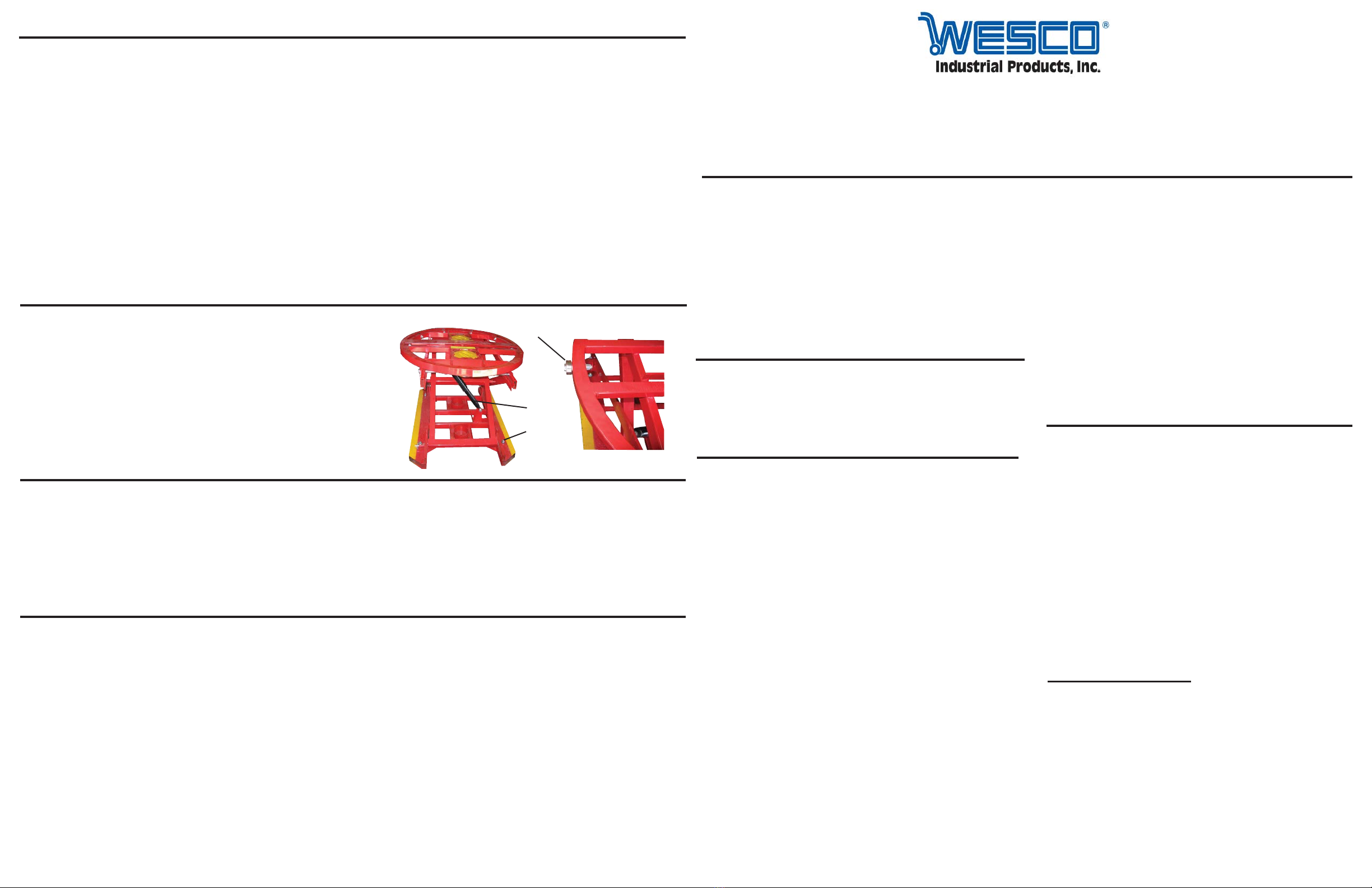
7. When installing the first (black) spring, have an
additional person to assist.
8. When installing the first (black) spring, use the
shock absorber pivot pin to support the frame
(Figure 1). This will prevent the frame from a
sudden drop.
9. Make sure after installing springs that they are
seated properly and that the spring locks are in
place.
10. When placing load on unit, make sure the
unit is supporting the weight, not the fork lift,
before removing the fork lift.
11. When removing a load with a fork lift, make
sure that the load is clear of the Pallet Lev
eler before moving the fork lift. If the load is
not clear of the Pallet Leveler, it may
suddenly release when the fork lift is
moved.
12. Never move the Pallet Leveler when it is
loaded. This would damage the base frame
since the fork pockets are designed to
support the weight of the unit, not the
extra load weight.
Start-up
1. Choose the place where you want to mount the
unit. The Pallet Leveler must be set up on a
clean andflat surface. Use optional leveling
pads
P/N 273000 to compensate for uneven floors.
2. Remove the plastic ties which secure the unit
to the base frame. Unpack three springs.
Remove all packing materials.
3. Check that frame of the unit is sitting firmly on
the floor. Pallet Leveler must be stable and
level. If unit is not level within 1/2" you must
use the optional leveling pads P/N 273000.
4. Remove the springs and place them on the
floor.
Installing the springs:
1. The Pallet Leveler can handle loads up to
4500 lbs. In order to adjust the Pallet Leveler
to adapt to different loads, the springs are
changed per the weight and height of the fully
loaded pallet. The Pallet Leveler may have
one to three springs, depending on the load.
Item Part No. Description Qty.
1 272988 Shock Absorber 1
2 272989 Bearing 16
3 272993 Spring: Black(not shown) 1
4 272994 Spring: *Ua\(not shown)  1
5 272995 Spring: 2raQJH (not shown) 1
6 272996 Kit: Hardware (not shown) 1
7 273000 Kit: Leveling Pad (optional) 1
Parts List
Warranty Repairs
If unit does not work properly, contact your dealer or the factory (215-699-7031), within one year of purchase date.
Non-Warranty Service
For units older than one year, repairs can be made easily on site with factory supplied parts, or repairs can be made at the
factory. NOTE: Do not send units to the factory for service without obtaining a “returned materials authorization" (RMA)
number from the service department. We will not be responsible for goods returned without proper authorization.
To Purchase Parts
A complete parts list with drawings appears in this manual. To order parts contact the factory at the phone or fax numbers
shown on page 1 of this manual. Ask for the Customer Service Department.l
LIMITED WARRANTY
Wesco Industrial Products, Inc. (WESCO) warrants to the purchaser of this product for a period of one year from the date of purchase
that this product shall be free of defects in material and/or workmanship, as follows:
1. WESCO will supply, at no charge, new or rebuilt replacements for any part that fails through a defect in material and/or workman-
ship during the warranty period.To obtain warranty service, you must deliver the product prepaid, to the WESCO factory.
2. This warranty does not cover any product or product part which has been subject to accident, misuse, abuse or negligence. WES-
CO shall only be liable under this warranty if the product is used in the manner intended by the manufacturer as specified in the written
instructions furnished with this product.
REPAIR OR REPLACEMENT AS PROVIDED UNDER THIS WARRANTY IS THE EXCLUSIVE REMEDY OF THE PURCHASER.
ANY EXPRESS WARRANTY NOT PROVIDED IN THIS WARRANTY DOCUMENT, AND ANY REMEDY FOR BREACH OF CON-
TRACT THAT, BUT FOR THIS PROVISION, MIGHTARISE BY IMPLICATION OR OPERATION OF LAW, IS HEREBY EXCLUDED
AND DISCLAIMED. UNDER NO CIRCUMSTANCES SHALL WESCO BE LIABLE TO PURCHASER ORANY OTHER PERSON FOR
ANY INCIDENTAL OR CONSEQUENTIAL DAMAGES, WHETHER ARISING OUT OF BREACH OF WARRANTY, EXPRESS OR
IMPLIED, A BREACH OF CONTRACT OR OTHERWISE. EXCEPT TO THE EXTENT PROHIBITED BYAPPLICABLE LAW, ANY
IMPLIED WARRANTY OF MERCHANTABILITYAND FITNESS FOR ANY PARTICULAR PURPOSEARE EXPRESSLY LIMITED IN
DURATION TO THE DURATION OF THIS LIMITED WARRANTY.
Some states do not allow the exclusion or limitation of incidental or consequential damages, or allow limitations on how long any
implied warranty lasts, so the above limitations may not apply to you. This warranty gives you specific legal rights, and you may also
have other rights which vary from state to state. © Copyright 2008 Wesco Industrial Products, Inc.
1
7
2
Troubleshooting
PROBLEM CAUSE CHECK
Unit lowers too easily. Wrong spring configuation, Check spring ratings,
springs too weak for load. Refer to table 1A and 1B.
Unit lowers too hard. Wrong spring configuation, Check spring ratings,
springs too strong for load. Refer to table 1A and 1B.
Top of unit rotates away Unit may not be level. Move to level surface or install
from operator. operational leveling pads, P/N 273000.
Top of unit bounces. Shock absorber damaged. Replace shock absorber.
Excessive "Rumble" when Damaged bearings under Replace bearings.
in operation. turntable.
1. Using Table 1A, find the correct
spring combination.
2. In Table 1B find the springs
included in the combination.
Figure 1
RANGE
1
2
3
4TABLE 1B
SPRING COMBINATIONS
WEIGHT OF LOADED PALLET IN POUNDS (LOAD AND PALLET)
Height of loaded
pallet in inches
(load and pallet) 0- 400- 800- 1200- 1600- 2000- 2400- 2800- 3200- 3600- 4000-
400 800 1200 1600 2000 2400 2800 3200 3600 4000 4500
58-60 in. - - 1 1 1 1 2 2 2 3 3
56-58 in. - - 1 1 1 2 2 2 2 3 3
54-56 in. - - 1 1 1 2 2 2 2 3 3
52-54 in. - 1 1 1 1 2 2 2 2 3 3
50-52 in. - 1 1 1 1 2 2 2 3 3 3
48-50 in. - 1 1 1 1 2 2 2 3 3 4
46-48 in. - 1 1 1 1 2 2 3 3 3 4
44-46 in. - 1 1 1 2 2 2 3 3 3 4
42-44 in. - 1 1 2 2 3 3 3 3 4 4
40-42 in. - 1 1 2 2 3 3 3 4 4 4
38-40 in. - 1 1 2 2 3 3 4 4 4 4
36-38 in. - 1 1 2 2 3 4 4 4 4 4
34-36 in. 1 1 2 2 3 3 4 4 4 4 -
32-34 in. 1 1 2 3 3 4 4 4 4 - -
30-32 in. 1 1 2 3 3 4 4 4 4 - -
TABLE 1A
SPRING SELECTION CHART
BLACK
AND ORANGE
SPRINGS
Figure 2
REAR = HINGE END
GRAY
SPRING
BLACK
SPRING BLACK
SPRING
BLACK
SPRING
GRAY
ORANGE
SPRING
Combination 1 Combination 2 Combination 3 Combination 4
Operation
1. Place pallet on unit, add load until pallet is full. The Pallet Leveler will gradually lower the pallet until it
reaches the the bottom.
2. When removing the load the Pallet Leveler will gradually raise the pallet.
3. When loading the pallet with a fork truck make sure the Pallet Leveler is carrying the weight, not the fork
truck, and the unit is fully compressed.
4. Make sure the load is centered on the unit before removing the fork truck.
5. When removing the load with a fork truck, insert the forks into the pallet and lift the pallet clear of the top
of the unit. Raise the pallet until the springs on the Pallet Leveler are fully extended. Make sure the
pallet clears the top of the turntable before you move the fork truck.
6. To relocate the Pallet Leveler, remove load from the top of the unit. Using a fork truck, insert the forksinto
the fork pockets in the base frame.
2. When the pallet weight or pallet height is
changed, the springs may also need to be
changed, to adjust the Pallet Leveler to the
correct pallet load. Tables 1Aand 1B show
how the springs are selected. Each spring
is color coded to identify the proper selection.
Every Pallet Leveler will always have one
spring. This spring has the largest diameter of
the three and is black in color. The black spring
is always positioned near the rear of the unit,
which is closest to the hinge. Figure 2 shows
the position of the black spring and any
additional springs which may be required.
3. Check to be sure you have the correct springs.
Calculate the weight of a fully loaded pallet,
including the weight of the pallet. Measure the
height of the fully loaded pallet. Refer to
Tables 1A and 1B to check if you have the
correct spring configuation for your application.
4. Lift the rotating ring away from the frame. This
will require two people
5. The shock absorber is attached to the frame
of the Pallet Leveler with a pivot pin,which is
held in place by a linch pin. This pivot pin (also
calledamaintenancepin) isusedduringspring
installation to hold the table frame in the raised
position. Remove the linch pin and the pivot
pin. Lay the free end of the shock absorber
down.
6. Lift the top part of the frame as far as it will go.
Insert the shock absorber pivot pin
(maintenance pin) into the lower roller guide.
This will require two people.
WARNING: The pivot pin (maintenance pin) is
designed to hold the frame of the Pal
let Leveler while you insert the first
spring. If you do not use it, an unsafe
condition will occur while inserting the
spring, as the frame of the Leveler
may suddenly drop.
SPRING REQUIRED
1 BLACK
1 BLACK AND 1 ORANGE
1 BLACK AND 1 GRAY
1 BLACK, 1 ORANGE AND 1 GRAY
The turntable pivots on a hinge at the rear.
The largest spring
(black) is mounted
near the rear of the
The pivot pin
must be removed from
the upper end of the
shock absorber and
inserted into the side
of the roller track.
The shock absorber
is disconnected and
laid to one side.. The top of the spring should fit behind the guide tab.
The front of the table is released
by removing the pivot shaft here.
The bottom of the spring should fit
over the round support.
7. Disconnect the front end of the table assembly
so you can tilt the table top back. The front end
of the assembly is held in place by a pivot shaft.
This shaft supports two rollers (located in the guide
slots of the frame) and is secured by a retaining
ring. Remove the retaining ring and slide the
pivot shaft out. Have additional personnel support
the top of the frame assembly as you remove the
pivot shaft.
8. Tilt the top frame assembly back as shown in
fig. 1. Install the largest spring (black); this spring
should be installed in the back of the unit, closest
to the hinge. The bottom of the spring should fit
over the round support on the base frame. The
top should fit behind the small guide shown in
fig. 1. When the spring is installed, slowly lower
the table top. Check each end of the spring to be
sure it has seated correctly.
9. As additional personnel support the weight of the
frame, align the holes in the frame and slide the
pivot shaft back into position, making sure the
roller wheels are in the guide slots. Install
retaining ring to hold pivot shaft in place.
10. The black spring will hold the unit up. Re-
assemble the shock absorber by inserting the
pivot pin and linch pin. Re -install the rotating
ring on the top frame; make sure the ring can
rotate. Table 1A & 1B may indicate that one or
two additional springs must be installed. To
add additional springs, remove the spring caps
and insert the springs through the top of the unit.
See figure 2 for proper spring placement. To
remove a spring cap, turn the cap
counterclockwise and lift upward. Insert the
spring through the opening. Replace the spring
cap and turn clockwise to lock it in place.
11. Make sure that each of the spring caps is firmly
in place. Inspect the top and bottom of each
spring and make sure the springs are seated
correctly. Inspect the linch pin at the top of shock
absorber, and the linch pin at the end of the
pivot shaft.
WARNING: Springs must be seated properly, and the
spring caps must be tightened to avoid
personal injury and damage to load.
R
F
R
F
R
F
R
F

Other Wesco Laser Level manuals

Wesco WS8915K User manual

Wesco

Wesco WS8915K User manual

Wesco WS8913K User manual

Wesco

Wesco WS8913K User manual

Wesco WS8911K User manual

Wesco

Wesco WS8911K User manual

Popular Laser Level manuals by other brands

Bosch GRL 400 H Operating/safety instructions

Bosch

Bosch GRL 400 H Operating/safety instructions

CONDTROL NEO X200 user manual

CONDTROL

CONDTROL NEO X200 user manual

Vega VEGACAP 63 operating instructions

Vega

Vega VEGACAP 63 operating instructions

Bosch PLL 1 P Original instructions

Bosch

Bosch PLL 1 P Original instructions

ADA INSTRUMENTS ROTARY 400 HV Servo operating manual

ADA INSTRUMENTS

ADA INSTRUMENTS ROTARY 400 HV Servo operating manual

ADA INSTRUMENTS CUBE MINI operating manual

ADA INSTRUMENTS

ADA INSTRUMENTS CUBE MINI operating manual

Bosch Quigo Original instructions

Bosch

Bosch Quigo Original instructions

Bosch GPL 3 Professional Original instructions

Bosch

Bosch GPL 3 Professional Original instructions

Bosch Quigo Original instructions

Bosch

Bosch Quigo Original instructions

Levenhuk Ermenrich LT20 user manual

Levenhuk

Levenhuk Ermenrich LT20 user manual

Umarex LaserLiner AquaPro 200 Operator's manual

Umarex

Umarex LaserLiner AquaPro 200 Operator's manual

Stanley STHT77616 manual

Stanley

Stanley STHT77616 manual

DeWalt DCLE34033 manual

DeWalt

DeWalt DCLE34033 manual

TOUGHBUILT TB-H2-LL-30-L2 Operating/safety instructions

TOUGHBUILT

TOUGHBUILT TB-H2-LL-30-L2 Operating/safety instructions

Laser Reference pro shot L1-M Service manual

Laser Reference

Laser Reference pro shot L1-M Service manual

LaserLiner Greenline-Laser 3P manual

LaserLiner

LaserLiner Greenline-Laser 3P manual

Bosch 2 Original instructions

Bosch

Bosch 2 Original instructions

VONROC LL501DC Original instructions

VONROC

VONROC LL501DC Original instructions

manuals.online logo
manuals.online logoBrands
  • About & Mission
  • Contact us
  • Privacy Policy
  • Terms and Conditions

Copyright 2025 Manuals.Online. All Rights Reserved.