8
West Mountain Radio Operating Manual
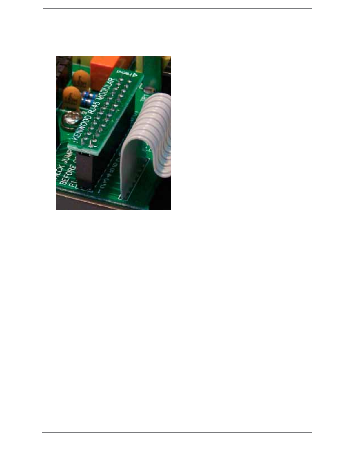
Choosing the Correct ISC
Conguring the RIGblaster Advantage with a transceiver is very simple
by use of the Instant Setup Connectors (ISC). These take the place of
jumper wiring for many common radios.
Each ISC is respectively identied: Icom Round Metal, Icom RJ45
Modular, Yaesu Round Metal, Yaesu Round Metel – Isolated, Yaesu
RJ45 Modular, Kenwood Round Metal and Kenwood RJ45 Modular.
Depending on the transceiver in use, one of these ISCs will need to be
installed inside the RIGblaster Advantage before use. They take care
of all the microphone connection wiring that previously was done by
installing jumper wires and shunts. If using a non-standard microphone
wiring, jumper wires and and blue shunts have been provided in the
package contents.
The ISCs cover most popular brands and models of radios.
Observe the microphone connector on the radio. Typically it will be one of
two types – either an 8-pin round metal connector or an RJ- 45 “square”
modular jack. The RIGblaster Advantage is designed to interface the
transceiver through the microphone jack. Be sure to select the ISC that
matches the connector on the radio.
Chart of ISCs For Some Common Radios:
Manufacturer Model ISC
Icom All 8 pin round mic jack radios (e.g., IC-746, IC-756/
Pro/III,IC-7600)
Icom 8 Pin Round
Icom All RJ-45 modular mic jack radios (e.g., IC-706, IC-
7000)
Icom RJ-45 Modular
Yaesu All older 8 pin round mic jack radios (e.g., FT-840, FT-
757, FT-920)
Yaesu 8 Pin Round
Yaesu All newer 8 pin round mic jack radios (e.g., FT-950, FT-
2000, FTDX-3000, FTDX-5000, FTDX-9000)
Yaesu 8 Pin Round- Isolated
Yaesu All RJ-45 modular mic jack radios (e.g., FT-817, FT-
857, FT-897, FT-450)
Yaesu RJ-45 Mdular
Kenwood All 8 pin round mic jack radios (e.g. TS-570, TS-2000,
TS-590S, TS-990S)
Kenwood 8 Pin Round
Kenwood Most RJ-45 modular mic jack radios (e.g. TM-V71) Kenwood RJ-45 Modular
Elecraft K3 & K2 use the same mic jack as Kenwood Kenwood 8 Pin Round
Ten Tec Omni VII & Orion II use the same mic jack as newer
Yaesu radios
Yaesu 8 Pin Round – Isolated
Flex Flex 1500 and 3000 use the same mic jack as Yaesu
RJ-45 radios
Yaesu RJ-45 Modular
Flex Flex 5000 and 6000 series use the same mic jack as
newer Yaesu radios
Yaesu 8 Pin Round - Isolated