Westermo DDW-100 User manual

Industrial Ethernet
SHDSL Extender
www.westermo.com
©Westermo Teleindustri AB • 2005
User Guide
6621-2201
DDW-100
Preliminary

26601-2201
Safety
Before using this unit:
Read this manual completely and gather all information on the unit. Make sure
that you understand it fully. Check that your application does not exceed the safe
operating specifications for this unit.
Hazardous voltage may occur within this unit when connected to power supply
or TNV circuits.
Prevent access to hazardous voltage by disconnecting the unit from power supply
and all other electrical connections.
Prevent damage to internal electronics from electrostatic discharges (ESD) by
discharging your body to a grounding point (e.g. use of wrist strap).
Before installation:
This unit should only be installed by qualified personnel.
This unit should be built-in to an apparatus cabinet, or similar, where access is
restricted to service personnel only.
The power supply wiring must be sufficiently fused, and if necessary it must be
possible to disconnect manually from the power supply. Ensure compliance to
national installation regulations.
This unit uses convection cooling.To avoid obstructing the airflow around the unit,
follow the spacing recommendations (see Installation section).
Care recommendations
Follow the care recommendations below to maintain full operation of unit and to fulfil
the warranty obligations.
This unit must not be operating with removed covers or lids.
Do not attempt to disassemble the unit.There are no user serviceable parts inside.
Do not drop, knock or shake the unit, rough handling above the specification may cause
damage to internal circuit boards.
Do not use harsh chemicals, cleaning solvents or strong detergents to clean the unit.
Do not paint the unit. Paint can clog the unit and prevent proper operation.
Do not expose the unit to any kind of liquids (rain, beverages, etc).The unit is not water-
proof. Keep the unit within the specified humidity levels.
Do not use or store the unit in dusty, dirty areas, connectors as well as other mechanical
part may be damaged.
If the unit is not working properly, contact the place of purchase, nearest Westermo dis-
tributor office or Westermo Tech support.
Maintenance
No maintenance is required, as long as the unit is used as intended within the specified
conditions.
!
!

36601-2201
Agency approvals and standards compliance
Type Approval / Compliance
EMC EN 61000-6-2, Immunity industrial environments*
EN 55024, Immunity IT equipment*
EN 61000-6-3, Emission residential environments*
FCC part 15 Class B*
EN 50121-4, Railway signalling and telecommunications apparatus*
IEC 62236-4, Railway signalling and telecommunications apparatus*
Safety EN 60950-1, IT equipment
UL listed, UL 60950-1*
CSA 22.2 No 60950-1-03*
SHDSL ITU-T G.991.2, G.SHDSL standard*
FCC Part 15.105 Notice: This equipment has been tested and found to comply with the
limits for a Class B digital device, pursuant to Part 15 of the
FCC Rules.These limits are designed to provide reasonable pro-
tection against harmful interference in a residential installation.
This equipment generates, uses and can radiate radio frequency
energy and, if not installed and used in accordance with the
instructions, may cause harmful interference to radio communica-
tions. However, there is no guarantee that interference will not
occur in a particular installation. If this equipment does cause
harmful interference to radio or television reception, which can
be determined by turning the equipment off and on, the user is
encouraged to try to correct the interference by one or more of
the following measures:
… Reorient or relocate the receiving antenna
… Increase the separation between the equipment and receiver
… Connect the equipment into an outlet on a circuit different
from that to which the receiver is connected
… Consult the dealer or an experienced radio/TV technician
for help.
* Approvals according to Westermo standard, in the Beta-release approvals may not be completed.

46601-2201
Declaration of Conformity

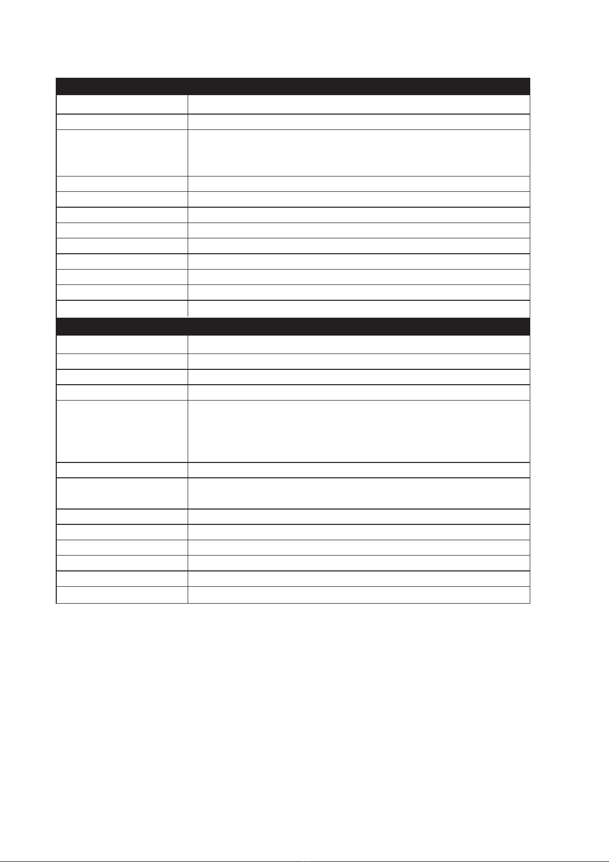
Electromagnetic Compatibility
Phenomena Test Description Level
ESD * EN 61000-4-2 Enclosure contact ± 6 kV
Enclosure air ± 8 kV
RF field AM modulated * IEC 61000-4-3 Enclosure 10 V/m 80% AM (1 kHz), 80 – 1 000 MHz
20 V/m 80% AM (1 kHz), 80 – 2 000 MHz
RF field 900 MHz * ENV 50204 Enclosure 20 V/m pulse modulated 200 Hz, 900 ± 5 MHz
Fast transient * EN 61000-4-4 Signal ports ± 2 kV
Power ports ± 2 kV
Surge * EN 61000-4-5 Signal ports unbalanced ± 2 kV line to earth, ± 2 kV line to line
Signal ports balanced ± 2 kV line to earth, ± 1 kV line to line
Power ports ± 2 kV line to earth, ± 2 kV line to line
RF conducted * EN 61000-4-6 Signal ports 10 V 80% AM (1 kHz), 0.15 – 80 MHz
Power ports 10 V 80% AM (1 kHz), 0.15 – 80 MHz
Power frequency EN 61000-4-8 Enclosure 100 A/m, 50 Hz, 16.7 Hz & 0 Hz
magnetic field *
Pulse magnetic field * EN 61000-4-9 Enclosure 300 A/m, 6.4 / 16 μs pulse
Voltage dips and EN 61000-4-11 AC power ports 10 & 5 000 ms, interruption
interruption * 10 & 500 ms, 30% reduction
100 & 1 000 ms, 60% reduction
Mains freq. 50 Hz * EN 61000-4-16 Signal ports 100 V 50 Hz line to earth
Mains freq. 50 Hz SS 436 15 03 Signal ports 250 V 50 Hz line to earth
Voltage dips EN 61000-4-29 DC power ports 10 & 100 ms, interruption
and interruption * 10 ms, 30% reduction
10 ms, 60% reduction
+20% above & –20% below rated voltage
Radiated emission * EN 55022 Enclosure Class B
FCC part 15 Class B
Conducted emission * EN 55022 AC power ports Class B
FCC part 15 AC power ports Class B
EN 55022 DC power ports Class B
Dielectric strength * EN 60950 Signal port to other 2 kVrms 50 Hz 1min
isolated ports
Power port to other 3 kVrms 50 Hz 1min
isolated ports 2 kVrms 50 Hz 1min (@ rated power < 60V)
Environmental
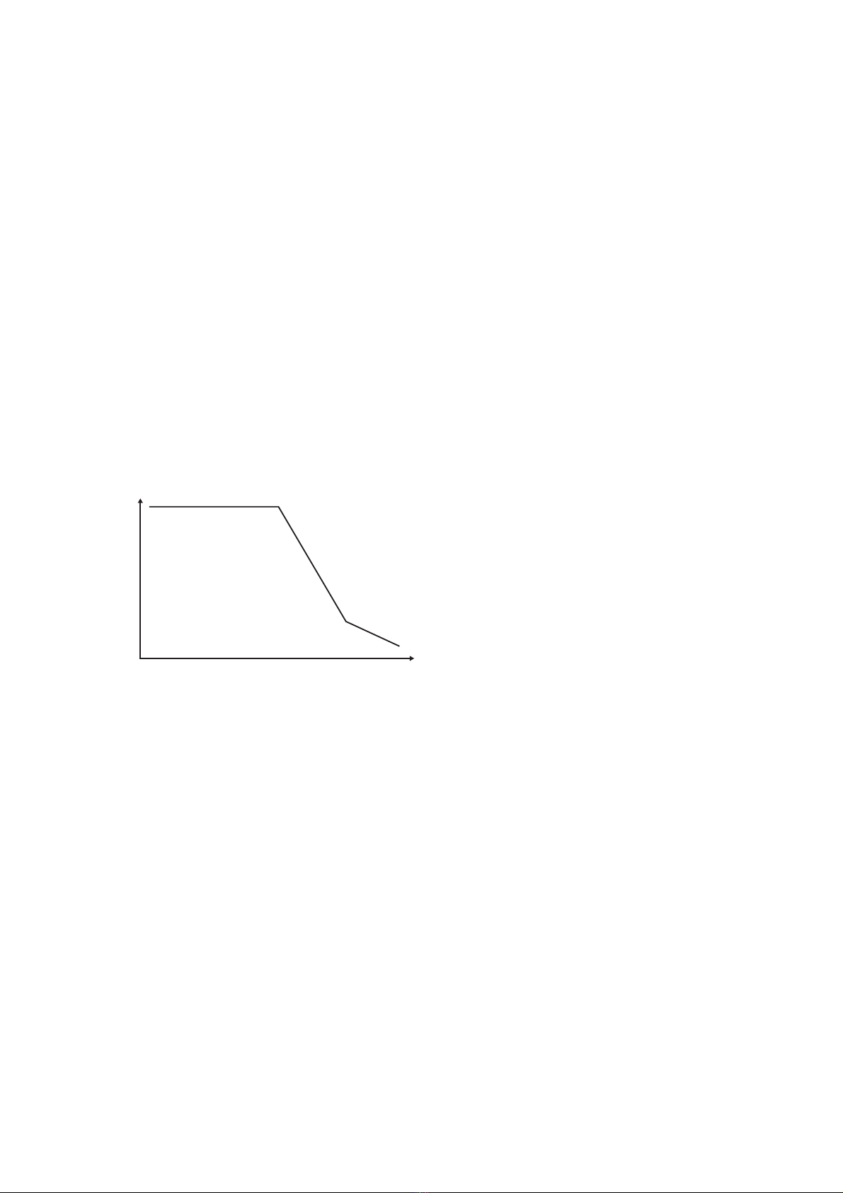
Temperature Operating –25 to +70°C
Storage & Transport –25 to +70°C
Humidity Operating 5 to 95% relative humidity
Storage & Transport 5 to 95% relative humidity
Altitude Operating 2 000 m / 70 kPa
Service life Operating 10 year
Vibration * IEC 60068-2-6 Operating 7.5 mm, 5 – 8 Hz
2 g, 8 – 500 Hz
Shock * IEC 60068-2-27 Operating 15 g, 11 ms
Packaging
Enclosure UL 94 PC / ABS Flammability class V-1
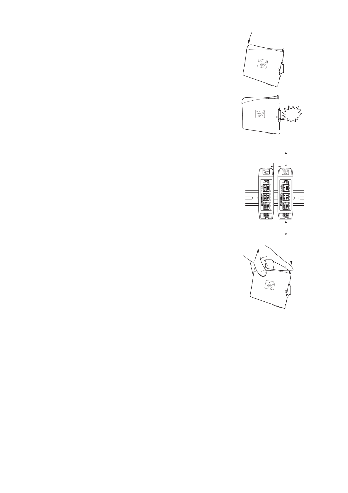
Dimension W x H x D 35 x 121 x 119 mm
Weight TBD kg
Degree of protection IEC 529 Enclosure IP 21
Cooling Convection
Mounting Horizontal on 35 mm DIN-rail
56601-2201
Type tests and environmental conditions
* Approvals according to Westermo standard, in the Beta-release approvals may not be completed

66601-2201
Description
Functional description
SHDSL represents the best of several symmetric DSL technologies that has been com-
bined into a single industry standard. DDW-100 is designed as a transparent Ethernet
Extender for 10/100BaseTX networks, it is transparent for multicast addressing, VLAN
packages, VPN pass through for IPSec and for protocols like MODBUS.
SHDSL provides the possibility to re-use existing twisted copper pair with data rates
from 192 Kbit/s to 2.3 Mbit/s in both directions (Symmetric DSL), according to standard
ITU-T G.991.2.
Based on the quality of the line and the communication speed the distance up to 6.5 km,
the distanse depends of the quality of the line and cable characteristics, this will differ
from application to application, therefore a unique feature is implemented for reliable
mode, high speed mode or normal mode.
Distance depending on speed without noise, cable type is AWG24
2500
2000
1500
500
1234567
kbit/s
Km

76601-2201
Getting started
DDW-100 is easy to use and install, the units work in pair, one as have to be configured
as CO (Central Office) and one as CPE (Customer Premises Equipment).This configura-
tion is made by DIP-switches placed under the lid in DDW-100.
Connect the SHDSL Line
There is two options for connecting the SHDSL line:
1) Connect the twisted pair to DSL screw terminal 1 and 2 (polarity independent)
placed in the bottom of DDW-100.
2) Connect the line through RJ-11 to the DSL line placed in the front of DDW-100.
Note! These two connections are parallel, it is not possible to use both at the same
time.
Connect the Ethernet Line
Connect Ethernet to the TX port placed in the front of DDW-100.
Factory settings for DDW-100 is plug and play mode where TX port is enabled for:
… Ethernet Auto-negotiation enabled.
… Auto MDI/MDI-X.
… Auto-polarity enabled.
DDW-100 will automatically sense the speed of the connected unit and if a crossed cable
is used.
Settings in the units
The units operates in pairs, one is working as CO (Central Office) and one as CPE
(Customer Premises Equipment). Factory setting in DDW-100 is as CO.
Note! Before connection and installation one of the connected unit have to be
reconfigured as CPE
Depending on the quality of the line and the distance there is possibility to select the
optimised speed.
This is done via DIP switches in the unit configured as CO. Factory default is 192 kbit/s.
When selecting higher speed note if the DSL link is established, if not, the selected speed
is to high fore the distance.

86601-2201
Interface specifications
Rated voltage 12 to 48 VDC
Operating voltage 10 to 60 VDC
Rated current TBD // TBD mA @ 12 VDC //
TBD // TBD mA @ 24 VDC //
TBD // TBD mA @ 48 VDC //
Rated frequency DC
Inrush current, I2t TBD // TBD A2s //
Startup current 1) TBD // TBD Apeak //
Polarity Reverse polarity protected
Redundant power input Yes
Isolation to 2000 Vrms to all other
Connection Detachable screw terminal
Connector size 0.2 – 2.5 mm2(AWG 24 – 12)
Shielded cable Not required
Power
Electrical specification ITU-T G.991.2 Annex B
Data rate 192 kbit/s to 2.312 Mbit/s
Protocol ITU-T G.991.2,Annex E Clear Channel Data
Circuit type TNV-1
Transmission range According to ITU-T G.991.2 depending on the line quality:
Typical values using noise-free AWG26 Cables
2.3 Mbit/s reach > 3 km
192 kbit/s reach > 6 km
Protection TBD if PTC or similar // Installation Fault Tolerant (up to ±60 V) //
Isolation to 2000 Vrms to power interface
2000 Vrms to Ethernet
Galvanic connection to None
Connection Detachable screw terminal and RJ-11
Connector size 0.2 – 2.5 mm2(AWG 24 – 12)
Shielded cable Not required
Conductive housing No
Number of ports 1
SHDSL Leased Line

96601-2201
Electrical specification RS-232/V.24
Data rate 115.2 kbit/s
Data format 8 data bits, none parity, 1 stop bit
Protocol Transparent
Retiming No
Circuit type SELV
Transmission range 15 m
Isolation to 2000 Vrms to power interface
1500 Vrms to Ethernet interface
1500 Vrms to SHDSL interface
Galvanic connection to RS-232
Connection 3-pin connector
Connector size 2.56 pitch
Shielded cable Not required
Conductive housing No
Miscellaneous Only for diagnostic purpose for support crew
Number of ports 1
RS-232, Diagnostic port intended for support purpose *
Electrical specification IEEE std 802.3. 2000 Edition
Data rate 10 Mbit/s, 100 Mbit/s, manual or auto
Duplex Full or half, manual or auto
Circuit type SELV
Transmission range 100 m
Isolation to 2000 Vrms to power interface
2000 Vrms to SHDSL interface
Galvanic connection to None
Connection RJ-45 shielded, auto MDI/MDI-X
Shielded cable Not required, except when installed in Railway applications as
signalling and telecommunications apparatus and located close
to rails 2)
Conductive housing Isolated to all other circuits
Miscellaneous If Auto-Neg. is disabled then this interface will be set MDI,
see below.
Number of ports 1
Ethernet TX
* Diagnostic port is not implemented in the Beta version.

10 6601-2201
Cooling
This unit uses convection cooling.To avoid obstructing the air-
flow around the unit, use the following spacing rules. Minimum
spacing 25 mm (1.0 inch) above /below and 10 mm (0.4 inches)
left /right the unit. Spacing is recommended for the use of unit
in full operating temperature range and service life.
Removal
Press down the black support at the top of the unit. See figure.
Mounting
This unit should be mounted on 35 mm DIN-rail, which is
horizontally mounted inside an apparatus cabinet, or similar.
Snap on mounting, see figure.
10 mm *
(0.4 inches)
25 mm
25 mm
* Spacing (left/right) recommended
for full operating temperature range
CLICK!

116601-2201
4-position Description
No. 1 Common
No. 2 +VA
No. 3 +VB
No. 4 Common
Position Direction Description
No. 1
No. 2
No. 3 In/Out 2-wire Receive/
Transmit
SHDSL
No. 4 In/Out 2-wire Receive/
Transmit
SHDSL
No. 5
No. 6
DSL
Power connection
screw terminal
Connections
Ethernet connection (TX)
Contact Signale Name Direction Description/Remark
No.1 TD+ In/Out Transmitted/Received data
No. 2 TD– In/Out Transmitted/Received data
No. 3 RD+ In/Out Transmitted/Received data
No. 4
No. 5
No. 6 RD– In/Out Transmitted/Received data
No. 7
No. 8
Shield HF-connected
DSL RJ-11 connector
Position Direction Description
No. 1 In/Out 2-wire Receive/
Transmit
SHDSL
No. 2 In/Out 2-wire Receive/
Transmit
SHDSL
SHDSL screw connector
DDW-100 supports redundant power connection.
The positive input are +VA and +VB, the negative
input for both supplies are COM. The power is
drawn from the input with the highest voltage.
CAT 5 cable is recommended.
Unshielded (UTP) or shielded (STP) connector might be used.
8
7
6
5
4
3
2
1

12 6601-2201
NOTE
Railway installation close to the rails.
For a cable located inside 3 m boundary and connected to this port, the use of shielded
cable is recommended, this is to minimise the risk of interference.The cable shield
should be properly connected (360°) to an earthing point within 1 m from this port.This
earthing point should have a low impedance connection to the conductive enclosure of
the apparatus cabinet, or similar, where the unit is built-in.This conductive enclosure
should be connected to the earthing system of an installation and may be directly con-
nected to the protective earth.
Description and sequence of DSL LED indicator
Definition of DSL units CO (Central Office).
CPE (Customer Premises Equipment).
Flash 1 (only in CO) Both CO and CPE have power and the line is connected.
Flash 2 (both in CO and CPE) Synchronisation phase of DSL link.
Flash 3 (both in CO and CPE) Activation phase of DSL link.
ON (both in CO and CPE) Unit has established a SHDSL connection.
LED Status Indication of
PWR OFF Unit has no power
ON Internal power
Slow flash Initialisation progressing
Fast FLASH Initialisation error
DSL * OFF Unit is unconnected
Flash 1 (200 ms) Unit is initializing DSL, only CO
Flash 2 (400 ms) Unit is in activation phase 1of DSL link establishment
FLASH 3 (1 s) Unit is in activation phase 2 of DSL link establishment
ON Unit has established a DSL connection
ON Serial data transmitted from the unit, (RS-232 or RS-422/485)
LINK OFF No Ethernet link
ON Good Ethernet link
Flash Ethernet data is transmitted or received, traffic indication
SPD OFF 10Mbit/s
ON 100Mbit/s
DPX OFF HDPX, Half Duplex
ON FDPX, Full Duplex
LED Indicators

136601-2201
S1* DIP-switch
DIP-switch settings
Before DIP-switch settings:
Prevent damage to internal electronics from electrostatic discharges (ESD)
by discharging your body to a grounding point (e.g. use of wrist strap).
NOTE DIP-switch alterations are only effective after a power on.
A setting configured by any other method during normal operation, overrides
the DIP-switch setting. However, at power up, the DIP-switch settings have
precedence over the setting configured by any other method.
!
S1
ON
12345678
Ethernet Auto-negotiation enabled.
Auto MDI/MDI-X.
10 Mbit/s auto-polarity enabled.
Auto-negotiaion enabled, CO, Normal Mode
ON
12345678
Speed 100 Mbit/s *
ON
12345678
Speed 10 Mbit/s *
ON
12345678
Full-Duplex, FDPX *
ON
12345678
Half-Duplex, HDPX *
ON
12345678
Central, CO
ON
12345678
Remote, CPE
ON
12345678
192 kbit/s
ON
12345678
384 kbit/s
ON
12345678
512 kbit/s
ON
12345678
768 kbit/s
ON
12345678
1.024 Mbit/s
ON
12345678
1.280 Mbit/s
ON
12345678
2.048 Mbit/s
ON
12345678
2.304 Mbit/s
* Configured as MDI • S1: 7 and 8 are not used
Factory settings
ON
12345678
S1

14 6601-2201
DIAGN.
PORT* 8-pos. DIP-switch
PHY
Memory
Power
Isolation
Isolation
Isolation
Screw
Connector Screw
Connector
SHDSL modem
RJ-11
Connector
RJ-45
Connector
Ethernet
Interface
LED
Power
SHDSL
Link
Application
Block diagram
* Diagnostic port is not implemented in the Beta version

156601-2201
DDW-100 as an transparent Ethernet extender
Network Network

REV.A 6621-2201 2005-11 Mälartryck AB, Eskilstuna, Sweden
Westermo Teleindustri AB • SE-640 40 Stora Sundby, Sweden
Phone +46 16 42 80 00 Fax +46 16 42 80 01
E-mail: info@westermo.se
Westermo Web site: www.westermo.com
Westermo Teleindustri AB have distributors in several countries, contact us for further information.
Westermo OnTime AS
Gladsvei 20 0489 Oslo, Norway
Phone +47 220 903 03 • Fax +47 220 903 10
E-mail: [email protected]
Westermo Data Communications Ltd
Talisman Business Centre • Duncan Road
Park Gate, Southampton • SO31 7GA
Phone: +44(0)1489 580 585 • Fax.:+44(0)1489 580586
E-Mail: sales@westermo.co.uk
Westermo Data Communications GmbH
Goethestraße 67, 68753 Waghäusel
Tel.: +49(0)7254-95400-0 • Fax.:+49(0)7254-95400-9
E-Mail: info@westermo.de
Westermo Data Communications S.A.R.L.
9 Chemin de Chilly 91160 CHAMPLAN
Tél : +33 1 69 10 21 00 • Fax : +33 1 69 10 21 01
E-mail : infos@westermo.fr
Subsidiaries
Other manuals for DDW-100
1
Table of contents
Other Westermo Extender manuals

Westermo
Westermo DDW-100 User manual

Westermo
Westermo Wolverine DDW-226 User manual

Westermo
Westermo 6642-22201 User manual

Westermo
Westermo Wolverine DDW-221 User manual

Westermo
Westermo WOLVERINE DDW-222 Series User manual

Westermo
Westermo Wolverine DDW-225 User manual

Westermo
Westermo DDW-120 User manual

Westermo
Westermo Wolverine DDW-142-12VDC-BP User manual

Westermo
Westermo DDW-142 User manual

Westermo
Westermo Wolverine DDW-142-485 User manual