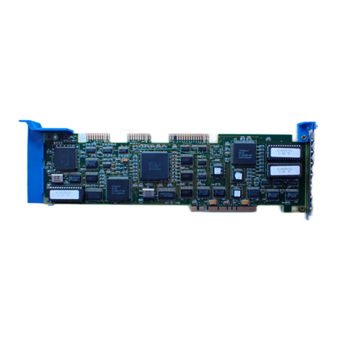
Western Digital WD1009V-SE2 User manual

Western Digital WD1009V-SE2
DEFAULT JUMPER SETTINGS
ÚÄLEDÄÄÄÄÄÄÄDRIVE 1ÄÄÄÄDRIVE 0ÄÄÄÄWINCHESTERÄÄÄÄÄÄÄÄFLOPPYÄÄÄÄÄÄÄÄÄÄÄÄ¿
³ .... :::::::::: :::::::::: ::::::::::::::::: ::::::::::::::::: ³
³ J6 1 J3 1 J4 1 J5 1 J3 ³
³ ³
³ W2. ³
³ W3 . ³
³ ³
³ ³
³ ³
³ ³
³W5:::::::::::: W6:::: ³
³ 1 ÚÄ¿ 1 ³
³ ÀÄÙ ³
³ U51 ³
ÀÄÄÄÄÄÄÄÄÄÄÄÄÄÄÄÄÄÄÄÄÄÄÄÄÄÄÄÄ¿ËËËËËËËËËËÚ¿ËËËËËËËËËËËËËËËËËËËËËËËËËÚÄÄÙ
³ºººººººººº³³ººººººººººººººººººººººººº³
Jumper closed: ÀÄÄÄÄÄÄÄÄÄÄÙÀÄÄÄÄÄÄÄÄÄÄÄÄÄÄÄÄÄÄÄÄÄÄÄÄÄÙ
Figure 1: WD1009V Controller
ÚÄLEDÄÄÄÄÄÄÄDRIVE 1ÄÄÄÄDRIVE 0ÄÄÄÄWINCHESTERÄÄÄÄÄÄÄÄFLOPPYÄÄÄÄÄÄÄÄÄÄÄÄ¿
³ .... :::::::::: :::::::::: ::::::::::::::::: ::::::::::::::::: ³
³ J6 1 J3 1 J4 1 J5 1 J3 ³
³ ³
³ W2. ³
³ W3 . ³
³ ³
³ W4.. ³
³ ³
³ ³
³W5:::::::::::: W6:::: ³
³ 1 1 ³
³ ÛÛÛ ³
³ U51 W7 ³
ÀÄÄÄÄÄÄÄÄÄÄÄÄÄÄÄÄÄÄÄÄÄÄÄÄÄÄÄÄ¿ËËËËËËËËËËÚ¿ËËËËËËËËËËËËËËËËËËËËËËËËËÚÄÄÙ
³ºººººººººº³³ººººººººººººººººººººººººº³
Jumper closed: ÀÄÄÄÄÄÄÄÄÄÄÙÀÄÄÄÄÄÄÄÄÄÄÄÄÄÄÄÄÄÄÄÄÄÄÄÄÄÙ
Figure 2: WD1009V Controller, EISA Enhanced Version
WD1009-SE2 (http://www.f anken-online.de/ymmv) Page 1 of 18

DEFAULT JUMPER OPTIONS
Jumpe W2
o 2-3 End-twisted floppy d ive cable
Jumpe W3
o 1-2 AT-Type 1.44 MB floppy d ive
Jumpe W4
o o Ca d always enabled
Jumpe W5
1-2 o o Alte nate secto s disabled
3-4 o o T anslation mode enabled
5-6 o o Fo ce 35/53 SPT
7-8 o o 4-Byte ECC
9-10 o o Multi-segmented adaptive look ahead caching enabled
11-12 o o P ima y BIOS add ess (C800:0)
13-14 o o 1009V BIOS enabled
15-16 o o ¿
17-18 o o ÁÄ IRQ14
19-20 o o DMA channel 6
21-22 o o P ima y ha d d ive add ess (1F0-1F7)
23-24 o o Ha d d ive cont olle enabled
Jumpe W6
1-2 o o Enabled floppy cont olle
3-4 o o DMA channel 2
5-6 o o P ima y floppy d ive add ess (3F0-3F7)
7-8 o o Single Speed. 1.2 MB 5.25" floppy d ive
Jumpe W7
EISA Auto-configu ation enabled
WD1009-SE2 (http://www.f anken-online.de/ymmv) Page 2 of 18

JUMPER OPTIONS
Jumpe W2
o 1-2 Cente -twisted floppy d ive cable
Jumpe W3
o 2-3 PS/2 Type 1.44 MB floppy d ive
Jumpe W4
Ca d enabled by the EISA host
Jumpe W5
1-2 Alte nate secto s enabled
3-4 T anslation mode disabled
5-6 Physical mode-SPT
7-8 7-byte ECC
9-10 Caching disabled
11-12 Seconda y BIOS add ess (CC00:0)
13-14 1009V BIOS disabled
15-16 ¿ ¿ o o ¿
17-18 ÁÄ IRQ11 o o ÁÄ IRQ12 o ÁÄ IRQ15
19-20 DMA channel 7
21-22 Seconda y ha d d ive add ess (170-177)
23-24 Ha d d ive cont olle disabled
Jumpe W6
Disabled floppy cont olle
DMA channel 3
Seconda y floppy d ive add ess (370-377)
Dual Speed. 1.2 MB 5.25" floppy d ive
Jumpe W7
o o EISA Auto-configu ation disabled
KEY
o o = OPEN
= JUMPERED
WD1009-SE2 (http://www.f anken-online.de/ymmv) Page 3 of 18

JUMPER DESCRIPTIONS
This section lists and desc ibes all jumpe settings fo the WD1009V.
CHANGING THE CONFIGURATION
In o de to change the jumpe configu ation, you may equi e a jumpe shunt fo each
setting you plan to change. Jumpe shunts a e small plastic b ackets that fit ove the
jumpe pins. These shunts may be pu chased f om a compute supply sto e.
To change the jumpe configu ation:
1. Refe to Table 1 to dete mine you configu ation.
2. To install a jumpe shunt, place the shunt ove the pins specified in Table 1.
3. Push the shunt into place until it is flush against the base of the jumpe block.
W2 JUMPER - FLOPPY CABLE TYPE FOR THREE FLOPPY DRIVES
The W2 jumpe specifies the type of floppy cable you a e using in you installation if you
a e installing a thi d floppy d ive. If you have the WD1009V-SE1 ha d d ive- only cont olle ,
the e a e no jumpe pins to configu e at this location. If you a e installing one o two floppy
d ives, do not change the default setting.
The default setting is a jumpe installed on pins 2-3, which enables an end-twisted floppy
cable fo th ee d ives. Remove the jumpe shunt f om pins 2-3 and install it on pins 1-2 if
you a e using a cente -twisted floppy cable fo th ee floppy d ives. If you a e unsu e of the
type of cable you a e using, efe to the Int oduction to dete mine you cable type.
W3 JUMPER - FLOPPY DRIVE TYPE
This jumpe applies to the WD1009V-SE2 Cont olle . This option allows you to configu e
the cont olle fo AT- o PS/2-type, 3 1/2", 1.44MByte floppy d ives. The default jumpe
setting is a jumpe shunt installed on pins 1-2 to select an AT-type floppy d ive (3 1/2"
1.44MByte). Remove the jumpe shunt f om pins 1-2 and install it on pins 2-3 to designate
a PS/2-type floppy d ive (3 1/2" 1.44MByte).
W4 JUMPER - EISA CONTROLLER ENABLE OPTION
This jumpe dete mines how you want the cont olle enabled in an EISA system. The
default setting fo W4 is no jumpe shunt installed. This enables the WD1009V Cont olle
at all times. Install a jumpe shunt on pins 1-2 to allow the EISA host to enable o disable
the WD1009V Cont olle . Leave this jumpe off if you a e wo king in an ISA system.
W5 JUMPER - ESDI DRIVE AND BIOS OPTIONS
The W5 jumpe block allows you to configu e a numbe of impo tant options, some of
which a e dependent on you ha d disk configu ation o ope ating system capabilities. The
default setting fo all W5 jumpe s is no jumpe shunt installed. You may need to efe to
you ha d disk d ive o ope ating system documentation in o de to co ectly set the
cont olle ca d.
WD1009-SE2 (http://www.f anken-online.de/ymmv) Page 4 of 18

ALTERNATE SECTOR PINS 1-2 allow you to enable o disable the alte nate secto
capability. Install a jumpe shunt ove these pins to enable the alte nate secto , which
ese ves one secto pe t ack fo bad secto swapping.
TRANSLATION MODE PINS 3-4 open enables T anslation Mode on the WD1009V
Cont olle . Install a jumpe shunt on these pins to disable the T anslation Mode. Be su e to
check you system capabilities in matching you d ive tables befo e you disable this
featu e.
SECTORS PER TRACK PINS 5-6 default setting fo ces you 10 o 15Mb/s d ive to 35 o
53 secto s pe t ack (SPT) mode. Installing a jumpe on pins 5-6 activates the Physical
Mode. Physical Mode pa amete s a e dete mined by the d ive jumpe settings.
ERROR CORRECTION CODE PINS 7-8 specify the byte size of the e o co ection code
(ECC). The cont olle default setting enables a 4-byte ECC. Installing a jumpe shunt on
pins 7-8 enables the 7-byte ECC, which is only used if you a e pe fo ming ce tain
diagnostics.
CACHEING PINS 9-10 allow you to enable o disable caching. The default setting (no
jumpe shunt installed), enables the 64KBytes of multi-segmented adaptive look ahead
caching. Caching inc eases ove all system pe fo mance by eading ahead and buffe ing
the data secto s likely to be used by the host on subsequent ead commands.
Install a jumpe shunt on pins 9-10 if you want to disable caching. In most cases, it is best
to leave caching enabled. Refe to you softwa e documentation fo info mation on how
caching affects you softwa e pe fo mance.
BIOS ADDRESS PINS 11-12 select the p ima y o seconda y BIOS add ess. Leave the
pins open to select the p ima y BIOS add ess (C800:0). If a BIOS add ess conflict exists,
install a jumpe shunt on pins 11-12 to select the seconda y BIOS add ess (CC00:0).
WD1009V BIOS PINS 13-14 allow you to enable o disable the WD1009V BIOS. You most
likely want to enable the WD1009V BIOS, which is the default setting (pins 13-14 open). If
you want to disable the WD1009V BIOS, install a jumpe shunt ove pins 13- 14.
IRQ PINS 15-16 and 17-18 function togethe to select the inte upt equest (IRQ) add ess.
Most ope ating systems wo k with IRQ 14, which is the default setting.
If no jumpe shunts a e placed on pins 15-16 and 17-18, then IRQ 14 is selected. If a
jumpe shunt is placed on pins 15-16 but not 17-18, IRQ 12 is selected. Leave pins 15-16
open and place a jumpe shunt on pins 17-18 to select IRQ 15. If jumpe shunts a e placed
on both sets of pins, IRQ 11 is selected.
EISA DMA PINS 19-20 allow you to select the Di ect Memo y Access (DMA) channel in
you EISA system. When EISA DMA mode is enabled, it uses this DMA channel. The
default setting of no jumpe shunt installed selects DMA channel 6. Install a jumpe shunt
on pins 19-20 to select DMA channel 7.
HARD DISK CONTROLLER I/O ADDRESS PINS 21-22 select eithe the p ima y o
seconda y ha d disk cont olle I/O add ess. Leave pins 21-22 open to select the p ima y
ha d disk cont olle add ess (1F0-1F7). Install a jumpe shunt on pins 21-22 to select the
seconda y ha d disk cont olle add ess (170-177).
HARD DISK CONTROLLER PINS 23-24 enable o disable the ha d disk cont olle . Leave
pins 23-24 open to enable the ha d disk cont olle . Place a jumpe shunt on the pins to
disable the ha d disk cont olle .
WD1009-SE2 (http://www.f anken-online.de/ymmv) Page 5 of 18

W6 JUMPER - FLOPPY CONTROLLER OPTIONS
This jumpe block allows you to set a numbe of featu es elated to you floppy cont olle .
These options apply only to the WD1009V-SE2 model. All default settings do not have a
jumpe shunt installed.
FLOPPY CONTROLLER PINS 1-2 allow you to enable o disable the floppy cont olle .
Leave pins 1-2 open to enable the WD1009V-SE2 floppy cont olle . Place a jumpe shunt
on pins 1-2 to disable the WD1009V floppy cont olle .
FLOPPY DMA PINS 3-4 allow you to select the Di ect Memo y Access (DMA) channel fo
the floppy cont olle . To select DMA channel 2, leave pins open. To select DMA channel 3,
install a jumpe shunt on pins 3-4.
FLOPPY CONTROLLER I/O ADDRESS PINS 5-6 select eithe the p ima y o seconda y
floppy cont olle I/O add ess. Leave pins 5-6 open to select the p ima y floppy cont olle
add ess (3F0-3F7). Install a jumpe shunt to select the seconda y floppy cont olle add ess
(370-377).
SPINDLE SPEED PINS 7-8 specify the spindle speed of 5 1/4" high density, 1.2MByte
floppy d ives. Leave pins 7-8 open to designate a single-speed 1.2MB 5 1/4" d ive. Install
a jumpe shunt ove these pins to designate a dual-speed 1.2MB 5 1/4" floppy d ive.
W7 JUMPER - EISA AUTOCONFIGURATION
The W7 jumpe allows you to enable o disable the EISA Auto-configu ation featu e of you
EISA enhanced ve sion of the WD1009V Cont olle . Refe to the Int oduction to identify if
you WD1009V Cont olle is capable of EISA Auto-configu ation. Remove the jumpe
shunt if you want to disable the EISA Auto-configu ation capability on you EISA-
compatible WD1009V. Leave the jumpe shunt on pins 1-2 to enable the EISA Auto-
configu ation featu e.
INSTALLATION
This section p ovides the steps necessa y to install you WD1009V Cont olle in you
PC/AT system.
* Step One: P epa ing fo Installation
* Step Two: Locating the Expansion Slot
* Step Th ee: Connecting the Ha d D ives
* Step Fou : Connecting the Floppy D ives
* Step Five: Installing the Activity LED
* Step Six: Installing the WD1009V Cont olle
STEP ONE:
PREPARING FOR INSTALLATION
Be su e the following a e complete befo e installing the WD1009V:
* The powe co d is emoved f om the compute
WD1009-SE2 (http://www.f anken-online.de/ymmv) Page 6 of 18

* The compute cove is emoved acco ding to the inst uctions in you system owne 's
manual
* The cont olle , ha d disk d ives, and floppy d ives a e co ectly configu ed
* You ha d disk and floppy d ives a e co ectly installed acco ding to the d ive
installation manuals
* A te mination esisto is installed on the last ha d d ive and last floppy d ive
* Connect the powe supply connecto to the d ives
* Any existing ha d d ive and floppy d ive cont olle is emoved o disabled f om you
system.
STEP TWO:
LOCATING THE EXPANSION SLOT
Caution: To avoid elect ical shock, make su e that all powe to you compute is off and
the powe co d is disconnected f om the powe outlet p io to opening you compute .
The WD1009V Cont olle fits into a 16-bit expansion slot o 32-bit EISA expansion slot
inside you compute . Once the cove is off the compute , you will ecognize an a ea
towa d the back of the compute that has expansion slots available fo pe iphe al ca ds.
This a ea may al eady have ca ds installed, such as a video g aphics ca d, o se ial po t
ca d. When installing the WD1009V, it is best to select the expansion slot that is closest to
the d ives in you system.
The e a e two possible types of expansion slots: a mothe boa d expansion slot, and a
ve tical side-mounted expansion slot. In this installation, the mothe boa d is located
beneath the expansion slot a ea, and the ca ds a e seated on the mothe boa d.
Slimme systems may have side-mounted ve tical expansion slots. Once you locate the
desi ed expansion slot, emove the expansion slot cove by loosening the sc ew that holds
the cove in place.
The inside of you compute may diffe f om the illust ations in this manual. Refe to you
compute installation o use manual fo the exact location of you system components.
STEP THREE:
CONNECTING THE HARD DRIVES
Note: Be su e to align pin 1 on the cable connecto s to pin 1 on the d ive connecto , and
on the cont olle connecto . Pin 1 on the cable is indicated by a notch on the connecto , o
the pin 1 line on the cable is colo coded. Damage may occu if the cables a e not p ope ly
connected.
This section p ovides info mation on connecting you ha d disk d ives to the WD1009V
Cont olle . Du ing connection, do not mistake the ha d disk d ive cont ol cable fo the
floppy cable. Also make su e that the d ives a e installed p ope ly befo e connecting them
to the WD1009V Cont olle .
To connect the ha d d ives to the cont olle :
1. Be su e the d ives a e p ope ly cabled togethe with the daisy chain cable when
installing two ha d d ives.
WD1009-SE2 (http://www.f anken-online.de/ymmv) Page 7 of 18

2. Connect the 34-pin cont ol cable connecto f om the ha d d ives to the J5 connecto .
Be su e to align pin 1 on the cable connecto to pin 1 on the cont olle connecto , and
d ive connecto s.
Do not confuse the ha d d ive daisy chain cable with a floppy daisy chain cable. They
a e not inte changeable.
3. Connect the 20-pin data cable f om the fi st d ive to the J4 connecto on the cont olle
connecto . Align pin 1 to pin 1 on the d ive and cont olle . The fi st d ive is the boot
d ive.
4. If you a e installing two d ives, connect the second d ive (d ive 1) data cable to the J3
cont olle connecto . D ive 1 is the second o D: d ive in a dual ha d d ive installation.
5. Connect the powe supply connecto to the d ives.
STEP FOUR:
CONNECTING THE FLOPPY DRIVES
Note: Skip this section if you a e disabling the floppy cont olle o a e installing the
WD1009V-SE1 Cont olle .
This section p ovides info mation on connecting you floppy disk d ives to the WD1009V-
SE2 Cont olle . Du ing connection, do not mistake the ha d disk d ive cont ol cable fo the
floppy cable. Also make su e that the d ives a e installed p ope ly befo e connecting them
to the WD1009V Cont olle .
To connect the floppy d ives to the cont olle :
1. Be su e the d ives a e p ope ly cabled togethe with the daisy chain cable when
installing two o mo e floppy d ives.
2. Connect the 34-pin floppy cable connecto f om the floppy d ives to the J1 connecto .
Be su e to align pin 1 on the floppy cable connecto to pin 1 on the cont olle
connecto and to the d ive connecto s.
Do not confuse the ha d d ive daisy chain cable with a floppy daisy chain cable. They
a e not inte changeable.
3. The ha d d ive connections a e also displayed since the ha d d ives a e connected to
the cont olle befo e the floppy d ives a e connected.
4. Route the floppy and ha d d ive cables in you system between the d ive a ea and
selected cont olle expansion slot. Do not fo ce the cables between system
components. The cables should not obst uct any ai flow paths o est between the
cont olle and compute cove .
STEP FIVE:
INSTALLING THE ACTIVITY LED
This is an optional step. If you system p ovides an activity light emitting diode (LED)
indicato fo you ha d d ives, install the connecto into the J6 connecto on the WD1009V
Cont olle .
WD1009-SE2 (http://www.f anken-online.de/ymmv) Page 8 of 18

STEP SIX:
INSTALLING THE WD1009V CONTROLLER
Once all of the d ives a e co ectly cabled to the WD1009V, you a e eady to install the
cont olle in you system.
1. Ca efully slide the cont olle boa d into the selected expansion slot.
2. P ess evenly on the edges of the cont olle boa d as you inse t it into the expansion
slot. You will feel the cont olle slip into place and seat fi mly in the slot.
3. Afte the boa d is fi mly seated in the expansion slot, secu e the cont olle to the
compute by tightening the sc ew on the expansion slot cove .
4. Make su e that all cables and powe co ds inside the compute a e eattached befo e
closing the compute .
5. Replace and install the compute cove acco ding to the inst uctions p ovided in you
compute installation manual.
6. Attach all cables and connecto s to the back of the compute . Plug in the powe co d.
The WD1009V is now installed. You now need to p epa e the d ives fo use by pe fo ming
some setup outines.
PREPARING THE WD1009V FOR USE
You d ive needs to be p epa ed fo use. You will need you ope ating system diskettes fo
this phase of installation. This section desc ibes the disk p epa ation p ocedu es fo you
system using the WD1009V BIOS outine and DOS ope ating system. If you a e using a
diffe ent ope ating system, efe to you ope ating system documentation fo set up
p ocedu es.
The WD1009V BIOS outine allows you to:
* pe fo m a low-level fo mat
* ead and ma k the ha d d ive defect tables
* pe fo m a ead ve ify
* pe fo m a su face analysis
* show the configu ation info mation
* set the BIOS options and d ive pa amete s
You DOS Debug utility allows you to access the WD1009V BIOS set up outines. The set
up outines a e displayed in an easy-to-use menu on you sc een.
ACCESSING THE WD1009V BIOS MAIN MENU
The WD1009V Setup Sc een is accessed th ough the DOS Debug utility.
1. Tu n the system powe on.
2. Boot the system f om the bootable DOS diskette.
WD1009-SE2 (http://www.f anken-online.de/ymmv) Page 9 of 18

3. Inse t the diskette that contains the Debug utility into d ive A:.
4. Type Debug at the sc een p ompt. P ess [Retu n].
5. A dash (-) p ompt is displayed. Type g=C800:5. This tells the system to access the
WD1009V BIOS outine f om the Cont olle .
If you set the WD1009V BIOS to the seconda y BIOS add ess, (jumpe W5 with a
jumpe shunt installed on pins 11-12), type g=CC00:5.
6. P ess [Retu n]. The WD1009V BIOS outine finds the d ive pa amete s and displays
the BIOS Main Menu.
* * * WESTERN DIGITAL UTILITIES COPYRIGHT 1990,Rev.X.XX * * *
PHYSICAL DRIVE PARAMS.
DRIVE 0 CYLINDERS 1632 HEADS 15 SPT 53
DRIVE 1 *** NONE SELECTED or NO DRIVE PRESENT ! ***
DRIVE 2 *** NONE SELECTED or NO DRIVE PRESENT ! ***
DRIVE 3 *** NONE SELECTED or NO DRIVE PRESENT ! ***
1) HELP.
2) LOW LEVEL FORMAT ALL OF DRIVE.
3) MARK DEFECT LIST AUTOMATICALLY.
4) MARK DEFECT LIST BY HAND.
5) VERIFY ALL OF DRIVE.
6) SURFACE ANALYSIS ON ALL OF DRIVE.
7) SHOW CONFIGURATION IINFORMATION.
8) SET BIOS OPTIONS, DRIVE TYPE & EXIT.
Enter Choice (1-8) -------->
1009V BI S Main Menu - Single Drive Installation
If only numbe s a e displayed in place of the d ive pa amete s and Main Menu, the d ive
select o cable connections may be w ong. If this occu s, you need to check you d ive
configu ation and installation. Make su e the d ive select is co ect fo the type of cables
used. Also be su e that pin 1 on each cable is p ope ly connected to pin 1 on the d ive and
cont olle connecto s.
SET UP PROCEDURES
Wa ning: A low-level fo mat e ases all data on you ha d disk d ive. Be su e to back up all
of you data befo e p oceeding.
The set up p ocedu es a e easy to pe fo m. The Main Menu and elated sc eens p ompt
you fo input and display elated info mation on sc een. To select an option f om the Main
Menu, simply type the desi ed numbe . We ecommend you follow the o de displayed on
the Main Menu when initially p epa ing you system fo use.
HELP
The Help sc een lists the options available on the WD1009V Main Menu. If you a e unsu e
of the function of a pa ticula selection, p ess 1 to display the on-sc een Help menu.
LOW-LEVEL FORMAT
You need to pe fo m a low-level fo mat on the ha d d ives installed in you system. P ess 2
WD1009-SE2 (http://www.f anken-online.de/ymmv) Page 10 of 18

f om the Main Menu to pe fo m a low-level fo mat on you d ive. The p ompt at the bottom
of the sc een asks you to ente the d ive numbe you want to fo mat. In most systems, the
C: d ive is D ive 0.
1. Ente the d ive numbe .
2. You a e asked if you a e su e you want to pe fo m this function, since all files on this
d ive will be w itten ove by the fo mat p ocedu e. Ente Y fo yes if you want to
pe fo m a low-level fo mat on the d ive and e ase any existing files.
3. The next p ompt p ovides you the final oppo tunity to quit the low-level fo mat
p ocedu e if you do not want to dest oy the files on the d ive. Ente Y to continue with
the fo mat outine.
4. Once the low-level fo mat is complete the sc een p ompt notifies you that the fo mat
was successful. P ess any key to continue.
If the fo mat failed, the sc een notifies you of the fo mat failu e. Check all ha dwa e
connections and installation p ocedu es.
DEFECT TABLE
The e a e two ways to ead the d ive defect map and c eate a defect table that ma ks all
bad secto s on the ESDI disk d ive: automatically, o by hand.
To c eate the defect table and ma k all bad secto s on the d ive automatically:
1. P ess 3 f om the Main Menu.
2. Ente the d ive numbe .
3. The following p ompt asks if you a e su e you want to pe fo m this ope ation, since
files will be w itten ove . Ente a Y to continue.
The defect table is automatically gene ated based on the d ive manufactu e 's defect list. If
you have enabled alte nate secto s, a bad secto can be moved to the alte nate secto
without having to ma k the secto as bad. This allows a nea e o -f ee d ive to be
p esented to the ope ating system.
Ma k the defect list by hand if you a e unable to ente the defect list automatically. To ma k
the defect list by hand:
1. Locate the manufactu e 's defect table p ovided on the physical d ive, o in the d ive
documentation.
2. P ess 4 f om the Main Menu.
3. Ente the d ive numbe .
4. The following p ompt asks if you a e su e you want to pe fo m this ope ation. Ente a Y
to continue.
5. Ente each bad secto sepa ately:
a. ente the cylinde numbe and p ess [Retu n].
b. ente the head numbe and p ess [Retu n].
c. ente the byte offset f om index and p ess [Retu n].
WD1009-SE2 (http://www.f anken-online.de/ymmv) Page 11 of 18

Continue this p ocedu e until all bad secto s a e ente ed and ma ked.
VERIFY DRIVE
This ve ification checks all eadable secto s. If a bad secto is found du ing this p ocess it
is added to the defect table and ma ked as bad. This ope ation takes time.
1. P ess 5 f om the Main Menu.
2. Ente the d ive numbe .
3. The following p ompt asks if you a e su e you want to pe fo m this ope ation since all
files will be lost. Ente a Y to continue and confi m the selection.
SURFACE SCAN ANALYSIS
This ope ation is simila to ve ifying the d ive, only the Su face Scan is mo e complete and
takes mo e time. To pe fo m a su face scan:
1. Ente 6 f om the Main Menu.
2. Ente the d ive numbe .
3. The following p ompt asks if you a e su e you want to pe fo m this ope ation since files
will be lost. Ente a Y to confi m the selection. Be su e to allow at least a few hou s fo
this ope ation to complete.
SHOW CONFIGURATION INFORMATION
P ess 7 to display the Configu ation menu. This menu allows you to display the cont olle
o d ive configu ation info mation.
Ente you selection f om this menu by p essing the desi ed numbe . The configu ation
info mation displays on sc een. This info mation can also be accessed th ough the Set
BIOS Options Setup Sc een selection.
* * * WESTERN DIGITAL UTILITIES COPYRIGHT 1990,Rev.X.XX * * *
CONFIGURATION MENU
1. HELP.
2. SHOW CONTROLLER CONFIGURATION.
3. SHOW DRIVE CONFIGURATION.
4. RETURN TO PREVIOUS MENU.
ENTER CHOICE (1-4) -------->
1009V BI S Show Configuration Menu
BIOS SETUP OPTIONS
Note: Not all non-DOS ope ating systems cu ently suppo t the WD1009V BIOS INT 13
handle , Block Mode, o EISA DMA. Refe to you ope ating system manual befo e
enabling these featu es.
Note: Block Mode and EISA DMA cannot be enabled at the same time.
WD1009-SE2 (http://www.f anken-online.de/ymmv) Page 12 of 18

P ess 8 f om the Main Menu to Set BIOS Options and D ive Type, and to display the BIOS
Options sc een. It is impo tant to configu e the WD1009V BIOS co ectly, acco ding to
you system configu ation.
* * * WESTERN DIGITAL UTILITIES COPYRIGHT 1990,Rev.X.XX * * *
PHYSICAL DRIVE PARAMS.
DRIVE 0 CYLINDERS 1632 HEADS 15 SPT 53
DRIVE 1 *** NONE SELECTED or NO DRIVE PRESENT ! ***
DRIVE 2 *** NONE SELECTED or NO DRIVE PRESENT ! ***
DRIVE 3 *** NONE SELECTED or NO DRIVE PRESENT ! ***
OPTIONS MENU
1) HELP.
2) SHOW CONFIGURATION.
3) WESTERN DIGITAL INT 13 BIOS : DISABLED
4) BLOCK MODE SIZE : DISABLED
5) EISA DMA Mode : DISABLED
6) POWER UP SCAN FOR DRIVE 2&3: DISABLED
7) SET DRIVE TYPE AND EXIT.
ENTER CHOICE (1-7) -------->
1009V BI S ptions Menu
HELP
P ess 1 f om the BIOS Menu to display a help sc een that lists and b iefly desc ibes the
BIOS set up options.
SHOW CONFIGURATION
P ess 2 f om the BIOS Menu to list the configu ation info mation fo the d ive o the
cont olle .
WESTERN DIGITAL INT 13 BIOS
P ess 3 f om the BIOS Menu to enable o disable the WD1009V BIOS INT 13 handle . The
INT 13 handle allows the use of Block Mode, EISA DMA fo the EISA enhanced ve sion of
the WD1009V, and the ope ating system to ecognize ESDI d ives that exceed the
528MByte limit.
BLOCK MODE SIZE
P ess 4 f om the BIOS Menu to enable and set the Block Mode size. Block Mode
dete mines the amount of data t ansfe ed at one time. We ecommend setting the Block
Mode size to the maximum 16. If you want to disable the Block Mode option, set Block
Mode to 0.
EISA DMA MODE
P ess 5 f om the BIOS Menu to enable the DMA mode fo you EISA-capable WD1009V.
WD1009-SE2 (http://www.f anken-online.de/ymmv) Page 13 of 18

POWER UP SCAN FOR DRIVES 2 & 3
P ess 6 f om the BIOS Menu to enable powe up scan fo you thi d and fou th ESDI
d ives. This option is used when installing two WD1009V Cont olle s.
SET DRIVE TYPE AND EXIT
P ess 7 f f om the BIOS Menu to display the d ive t anslation tables fo the selected d ive.
The t anslation table selected dete mines how the system will see the d ive. The available
t anslation tables a e displayed on sc een.
You t anslation tables (the actual numbe s fo the cylinde s, heads, and secto s pe t ack)
may be diffe ent f om those displayed below.
* * * WESTERN DIGITAL UTILITIES COPYRIGHT 1990,Rev.X.XX * * *
PHYSICAL DRIVE PARAMS.
DRIVE 0 CYLINDERS 1632 HEADS 15 SPT 53
DRIVE 1 *** NONE SELECTED or NO DRIVE PRESENT ! ***
DRIVE 2 *** NONE SELECTED or NO DRIVE PRESENT ! ***
DRIVE 3 *** NONE SELECTED or NO DRIVE PRESENT ! ***
DRIVE TYPES FOR DRIVE: 0
*** NONE SELECTED or NO DRIVE PRESENT ! ***
CYLINDERS 1023 HEADS 15 SPT 53
CYLINDERS 1023 HEADS 16 SPT 17
> CYLINDERS 1023 HEADS 16 SPT 63
CYLINDERS 1630 HEADS 15 SPT 53 NEEDS CUSTOM DRIVER FOR THIS TABLE
CYLINDERS 321 Heads 64 SPT 63 MUST HAVE CUSTOM INT 13 BIOS INSTALLED
USE ↑ Or ↓ TO PICK DRIVE TYPES <ENTER> TO SET DRIVE TYPE.
1009V BI S Drive Translation Tables
The following five choices a e offe ed to p ovide flexibility fo you ope ating system and
d ive configu ation. We ecommend you use the thi d table fo ESDI d ives with less than
528Mbytes, and the fifth table fo d ives ove 528Mbytes. If you select the fifth table, you
must enable WD1009V BIOS INT 13. Refe to BIOS Setup Options fo mo e info mation.
The fi st table lists the physical pa amete s but t uncates the numbe of cylinde s to a
maximum of 1023, which could cause a loss of capacity on a la ge d ive.
The second table t uncates the numbe of cylinde s to 1023, inc eases the numbe of
heads to 16, and dec eases the secto s pe t ack to 17.
The thi d table allows the DOS maximum numbe of cylinde s, heads, and secto s pe
t ack. This table affo ds a maximum of 528MBytes.
The fou th table lists the actual physical pa amete s fo the d ive. Select this t anslation
table only if you have an ope ating system o a custom d ive that suppo ts the physical
d ive pa amete s of you d ive.
The fifth d ive t anslation table allows you to use the full capacity of d ives with mo e than
528MBytes. You need to enable the WD1009V INT 13 to use this table.
SELECTING THE TRANSLATION TABLE
To select a t anslation table, use the up and down a ow keys to move th ough the tables
WD1009-SE2 (http://www.f anken-online.de/ymmv) Page 14 of 18

listed. Place the pointe that appea s on the left side of the sc een in f ont of the desi ed
t anslation table. P ess [Retu n] to select the t anslation table fo each d ive. If the e is
anothe d ive installed, the sc een displays the t anslation tables fo that d ive. Select the
app op iate t anslation table and p ess [Ente ]. This p ocess continues until all installed
d ives have an assigned t anslation table.
If you only have one d ive installed, o when you have completed selecting the t anslation
table fo the last d ive installed, p ess [Retu n] a few times to exit the BIOS Menu. The
system automatically eboots.
PARTITIONING
You need to pa tition the ha d disk once the system is ebooted. The Fdisk p og am on
you DOS diskette sets up pa titions on you d ive.
To pa tition you ESDI d ives:
1. Boot f om a bootable DOS diskette.
2. Install the DOS diskette that contains the Fdisk p og am.
3. Type Fdisk at the p ompt.
4. P ess [Ente ].
5. Follow the inst uction displayed on sc een to pa tition you ESDI d ives. Be su e to
make the boot pa tition the active pa tition in o de to boot f om you ha d d ive.
Fo mo e info mation on pa titioning and Fdisk, efe to you ope ating system
documentation.
HIGH-LEVEL FORMATTING
High-level fo matting installs the ope ating system and p epa es you disk to accept files.
To pe fo m a high-level fo mat:
1. Reboot f om a bootable diskette.
2. Install the DOS diskette that contains the Fo mat p og am in d ive A:.
3. At the p ompt, type Fo mat C:/S to install DOS on the C: pa tition.
4. P ess [Retu n].
5. Ente Y to fo mat.
Once the fo mat p ocedu e is complete, you can use you ha d d ive in you system, and
boot f om the ha d d ive. Remove the DOS diskette f om d ive A:. P ess [Ct l], [Alt], and
[Del] simultaneously to eboot you system f om the fi st ha d d ive.
Once you eboot you system, the sc een should display the C: p ompt. If this does not
occu , o if you encounte e o messages, efe to you ope ating system manual o the
T oubleshooting section fo info mation on esolving p oblems.
You WD1009V installation is now complete and you system is eady fo use.
WD1009-SE2 (http://www.f anken-online.de/ymmv) Page 15 of 18

TROUBLESHOOTING
Note: If you system CMOS set up is e ased and the WD1009V BIOS was used to low-
level fo mat you ha d d ive, use you system configu ation utility to eset the ha d d ive
type to Type 1 fo each ESDI d ive.
This section desc ibes p oblems and lists p ocedu es to esolve some common difficulties
you may encounte with the WD1009V Cont olle . A table of possible e o messages and
solutions is also p ovided.
If you system does not co ectly boot and display the C: p ompt:
* Check you ha d disk and floppy disk d ive configu ations to be su e the d ives a e
p ope ly configu ed fo use in you system, and fo use with the WD1009V Cont olle .
Refe to Configu ing You D ive and you d ive installation manual to be su e you
followed configu ation and installation inst uctions co ectly.
* Check you WD1009V Cont olle configu ation to be su e the cont olle is p ope ly
configu ed fo use in you system. Refe to Configu ing. The WD1009V Cont olle to
be su e you followed the configu ation inst uctions co ectly.
* Re- ead the installation inst uctions p ovided in this manual to be su e that you
followed all installation p ocedu es.
* Refe to you system documentation and P epa ing The WD1009V Fo Use to be su e
you co ectly followed set up, pa titioning, and fo matting p ocedu es.
* Check the ha dwa e installation of you system. Check the following:
- A e the cables co ectly connected? Did you use the co ect cables when connecting
the ha d disks and floppy d ives?
- Check the cont olle ca d installation. Is it p ope ly seated, and connected?
- Is the system powe supply sufficient? Is the system powe supply wo king? Is the
powe p ope ly connected to you system and d ives?
- Is the activity LED always on? Check the LED cable connection.
The following table lists possible e o messages and solutions.
If you have fu the questions o t ouble, contact you deale o Weste n Digital Technical
Suppo t.
ERROR MESSAGES
P oblem Solution
No Response 1. Check you cable connections. Make
Sc een does not su e you did not inte change floppy
display C:\ disk d ive cables with ha d d ive
cables.
2. Check you system set up
configu ation.
3. Make su e the powe supply is
connected to each d ive.
WD1009-SE2 (http://www.f anken-online.de/ymmv) Page 16 of 18

4. Check you video ca d connection.
***Weste n Digital Utilities 1. Check the D ive Select Jumpe s on the
Copy ight 1990. Rev X.XX*** ha d d ive. (DRIVE 0)
Physical D ive Pa ams 2. Be su e that the d ive cables a e
Cylinde s 65535 connected p ope ly. Is pin 1 connected
Heads 65535 SPT 65535 to pin 1?
3. Ve ify the ha d d ive cable type.
Make su e the ha d d ive cable has
five twisted wi es and not seven if
you a e using a twisted cable.
Physical D ive Pa ams Make su e the systems CMOS is set to
D ive 0 Testing D ive D ive Type 1 if you a e using the
Please Wait WD1009V BIOS. Consult you system
Divide Ove flow manual.
Ha d Disk 0 Failu e 1. Make su e the ha d d ive cable is
Non System Disk o connected f om pin 1 to pin 1 on
D ive E o the d ive and cont olle .
2. Make su e powe is connected to
each d ive.
Missing Ope ating If the cont olle has been eplaced
System o changed, make su e cont olle
jumpe settings match.
EISA AUTOCONFIGURATION
The e a e two ve sions of the WD1009V cont olle . This section discusses the enhanced
EISA Auto-configu ation-capable ve sion. While eithe ve sion of the WD1009V may be
used in an EISA o ISA system, only the enhanced ve sion is capable of EISA Auto-
configu ation.
To dete mine if you have the enhanced ve sion, check location U51 on the cont olle . If
the e is a chip p esent, you have the enhanced ve sion capable of EISA Auto-
configu ation.
Figu e 2 shows the WD1009V with the chip installed at location U51. The following
inst uctions a e fo the EISA enhanced ve sion of the WD1009V only.
Most systems equi e jumpe W4 to be left open so that the WD1009V is always enabled.
Install a jumpe shunt on jumpe W7, pins 1-2 to enable the EISA Auto-configu ation
featu es of the WD1009V Cont olle .
Remembe that jumpe s W1, W2, W3, W4, and W7 need to be set manually. They cannot
be cont olled th ough the auto-configu ation.
To use you EISA system's Auto-configu ation, you need to load the WD1009V-SE1/SE2
Auto-configu ation files on to you system du ing configu ation. These files a e on a
diskette included with the enhanced cont olle . They may also be downloaded f om the
Technical Suppo t Bulletin Boa d.
Follow you EISA system configu ation utilities manual fo inst uctions on configu ing you
WD1009-SE2 (http://www.f anken-online.de/ymmv) Page 17 of 18

EISA system.
INSTALLING THREE OR FOUR HARD DRIVES
You can install up to fou ha d d ives in you system with the use of two WD1009V
Cont olle s. Each WD1009V Cont olle can inte face two ESDI d ives.
Most ope ating systems do not suppo t mo e than two ha d d ives. This installation will
p obably equi e softwa e d ive s. Refe to you ope ating system o thi d pa ty softwa e
vendo fo mo e info mation.
When installing th ee o fou ha d d ives, each pai of d ives a e cabled acco ding to the
installation inst uctions in Installing The WD1009V Cont olle . Connect two d ives to each
cont olle .
When p epa ing and installing the cont olle s and d ives in you system, you need to
dete mine which cont olle will be designated as the second cont olle . Configu e the
second cont olle to the seconda y I/O Add ess and DMA channel. Also configu e the
second cont olle with a diffe ent IRQ add ess. The BIOS and floppy cont olle must both
be disabled on the second cont olle .
When p epa ing the d ives fo use th ough the BIOS options in the WD1009V BIOS Main
Menu, be su e to enable the Powe Up Scan fo D ives 2 & 3 option. This enables the
powe up scan fo you thi d and fou th d ives.
WD1009-SE2 (http://www.f anken-online.de/ymmv) Page 18 of 18
Table of contents
Other Western Digital Controllers manuals
Popular Controllers manuals by other brands

Fife
Fife CDP-01 Additional instruction manual

ZyXEL Communications
ZyXEL Communications NXC5500 quick start guide

Milltronics
Milltronics EnviroRanger ERS500 instruction manual

Armacost Lighting
Armacost Lighting RGB14REM quick start guide

BERMAD
BERMAD Subtv Installation & operation manual

Hitachi
Hitachi EH-RMP2 Applications manual