Western Global TRANSCUBE GLOBAL 05TCG-EU User manual

TRANSCUBE GLOBAL
05TCG-EU, 10TCG-EU, 20TCG-EU
& 30TCG-EU
INTERMEDIATE BULK CONTAINER
Instruction Manual
W001.014 WL092

1
INDEX
Introduction
1
Spillages
9
Description
1
Statutory Inspection & Maintenance
10
Technical Specification
2
Environmental Responsibility
11
General Safety
2
Dispensing Fuel
11
Limitations of Use
2
Disposal
12
Safe Practice / Rules & Regulations
2
Modifications
12
Know Your IBC
3
05TCG-EU Specification Sheet
13-15
Positioning
4
10TCG-EU Specification Sheet
16-18
Lifting
4-7
20TCG-EU Specification Sheet
19-21
Trailer Mounted
8
30TCG-EU Specification Sheet
22-24
Earthing Point
8
Record Card
25
Access & Security
8
Warranty Claim Form
26
Port Positions / Connections / Pumps
8
Warranty
27
Filling the IBC
9
Notes
28
Bund Maintenance
9
INTRODUCTION
Thank you for choosing a Western Global TransCube Global IBC (Intermediate Bulk
Container). Please read the contents of this manual before using it.
Make sure everyone responsible is fully conversant with the procedures for, moving, filling,
positioning and maintaining the unit.
By following, understanding and practicing the information and procedures in this manual,
your Western Global IBC will give you many years of safe use.
Certain information in this manual is governed by law and is subject to change without prior
notice. Great care has been taken to ensure that the information is correct at the time of
publication. However, it is the owners / users sole responsibility to ensure that they and
the IBC fully comply with all legal requirements. Western Global Ltd cannot and will not
accept liability for any inaccuracy or incorrectly stated legal requirements.
Western Global Ltd reserves the right to alter product specifications without prior notice or
obligation.
DESCRIPTION
The TransCube Global range of IBC’s have been designed to enable safe storage and
transportation of diesel fuel. The IBC can be used to as an auxiliary fuel tank, feeding up to
three engines simultaneously, whilst refuelling other equipment via a dedicated fuel pump
at the same time. All pipe work and pump systems are stored beneath a secure, lockable
access hatch.
Each IBC conforms to UN/ADR which allows the transportation of the unit whilst containing
fuel. There is no need to drain / empty before transporting.
To aid both transporting and handling, the IBC is fitted with fork lift locating tubes, tie down
points and ‘full load’ crane sling lifting points. Internal baffles ensure safe control of fuel
movement when the unit is being lifted.
The IBC can be stacked two high when full or three high when empty.
Fully bunded, with a bund capacity equal to 110% of the main tank capacity. The design
enables maintenance of the bund area without the need for specialist equipment.

2
TECHNICAL SPECIFICATION
The dimensions and weights stated in this specification table are approximate and may
very slightly from the unit you have.
MODEL
CAPACI
TY
DIMENSIONS (mm)
WEIGHT (kg)
-
Litres
Length
Width
Height
Unladen
Laden
05TCG-EU
500
1150
1150
838
437
862
10TCG-EU
950
1150
1150
1320
514
1377
20TCG-EU
2000
2300
1150
1320
865
2665
30TCG-EU
3000
2300
1550
1320
992
3692
GENERAL SAFETY
Before using this equipment and to avoid personal injury, carefully read and understand
these instructions. If there is anything you do not understand, contact the supplier for
advice.
This IBC must not be moved, filled, maintained or operated by persons who are under the
influence of alcohol or drugs, tired or unwell.
You MUST perform a risk assessment before using this equipment to ensure your safety and
the safety of others.
Wear the correct Personal Protective Equipment for the task you are performing.
Wear gloves when handling this equipment. Wear suitable clothing.
Steel toecap boots must be worn. If appropriate, wear a hard hat.
Do not wear loose jewellery or clothing that may get in the way or become trapped in the
mechanism.
Inform everyone in the work area of what you are doing.
Inspect the IBC before use, if there is any doubt about its condition, DO NOT USE IT.
Western Global consider the corner brackets come under the definition of lifting points and
as such are part of the load (LOLER: ACOP 124).
LIMITATIONS OF USE
The IBC is designed for the safe storage of diesel fuel / heavy oils whilst on site or during
transportation. Each unit is capable of storing up to a maximum of 95% of its stated total
capacity, please see ‘Technical Specifications’ for details of the model you have.
SAFE PRACTICE / RULES AND REGULATIONS
The storage, transportation and dispensing of diesel fuel is governed by law and it is the
user / operator who has sole responsibility to ensure that any such rules and regulations
are abided by.

3
KNOW YOUR IBC

4
POSITIONING
Standalone Unit
Where the IBC is to be permanently positioned (long or short term) it is important that
certain aspects are considered. The position should be selected where it will be protected
from accidental impact. You should also make sure that both supplying vehicles and
receiving vehicles have safe and easy access to the IBC.
Consideration should be given to the location of overhead services such as
telecommunications and power cables and overhanging obstructions. Be aware of the
location of underground services, such as drains and manhole covers.
You must also consider the ground surface and make sure it is capable of supporting the
weight of the IBC, its contents when full and any stored equipment such as pumps, without
the risk of subsidence. It should be positioned on smooth and level ground with access
available to the rear and sides.
Allow for access that may be required by the emergency services should it become
necessary.
Stacked Units
Stacking of units is permissible up to 2 high when both full or three high where all are
empty. Where stacking is required the same rules apply as with a standalone unit. Do
remember to take into consideration the total possible weight of stacked unit.
LIFTING
Forklift / Tele-handler
Each IBC is fitted with forklift locating tubes which are designed to allow the IBC to be
raised by a fork lift / tele-handler. There are two sets of tubes allowing the IBC to be lifted
from either side or either end.
It is important that the total weight of
the IBC is not more than half (50%) of
the forklift’s maximum SWL.
Ensure that the forklifts forks are set
to the correct width for the IBC’s fork
tubes. Make sure that they are
equidistant from the centre.
Crane and Chain Slings; Lifting Points
The IBC must ONLY be lifted via the lifting / stacking
bracket found in each corner. ALL four corner
brackets must be used during a lift. The lifting /
stacking brackets MUST be inspected for condition
and safe use at regular intervals. The inspection must
be carried out by a competent person in accordance
with regulations and a record kept.
DO NOT lift from the base with polyester slings.

5
Lifting Equipment
You will require a lifting device (crane) and suitable
four-leg chain sling fitted with hooks and safety
catches. Note that most chain slings SWL are rated
at 90 degrees and the SWL usually decreases,
depending upon the angle the chain is used at.
Always check and obtain official confirmation
Bracket from the chain sling supplier that it is both
suitable in SWL and chain length.
Attaching the Lifting Equipment
With the chain sling correctly attached to the lifting
equipment, attach each hook to the lifting /
stacking bracket on all four corners. Once attached, ensure the hook’s gate is closed.
Attach tag lines to the base of the unit to control rotation.
LIFT ONLY ONE UNIT AT A TIME.
Lifting
Lift the chains until taut and check that the hooks are correctly positioned with gate closed
and that the chains are not twisted. If a fault is found, lower the chain and reattach
correctly.
WARNING
DO NOT ALLOW ANYONE UNDER THE RAISED LOAD AT ANY TIME OR FOR ANY REASON
Lift the unit until just off of the ground and check that it is balanced and stable. Once you
are satisfied that everything is correctly and safely set up, you can continue with the lift.
Use suitable tag lines to help control the movement of the unit and always keep constant
communication with the crane operator.
Move slowly and smoothly to ensure full control of the units whereabouts.
Lowering
Lower the unit to its required resting place using great care.

6
LIFTING INSTRUCTIONS
Lifting Instruction (summary)
1. Insure all 4 lifting points are used.
2. Insure lift equipment and accessories are certified to lift the MGW stated on the
label.
3. Lift with caution.
LIFTING POINT INSPECTION / MAINTENANCE
All lifting points must be visually inspected at suitable intervals. The intervals and scope of
inspection should be determined by a competent person in the users or owners
organisation in accordance with the safe use of work equipment (PUWER Reg.6).
Some examples of possible defects:
Bent gusset plate
at lift point.
Spilt or fractured
weld at lift point.
Loose or missing bolts
Note: Corner brackets bolted with M12 8.8, nyloc nut with Form C washers
tighten to 80N/M

7
LIFTING POINT EXAMINATION RECORD CARD
Tank Model: ___________________ Tank Capacity: _________________
Safe Working Load: _____________kg Date of Manufacture: ___________
Date of
Inspection
Name of
Inspector
Address of
Inspector
Address of
Premises of
Examination
Pass /
Defected
Notes
Ref.
Next
Examination
Date
Notes: (e.g. Defects/Action taken + date/To whom reported)

8
TRAILER MOUNTED
The IBC is available mounted on a trailer as supplied by Western Global. Please refer to the
‘trailer manual’ supplied with the IBC for all information regarding the trailer and its safe
use.
EARTHING POINT
The IBC is fitted with an earthing point found on the
outside edge of one fork tube, usually at the access
point end.
Used to protect against static electricity build up, it
should be connected to a suitable earthing point by a
qualified electrician.
ACCESS AND SECURITY
The IBC is fitted with a range of connections to
enable the user to supply direct connections
and/or controlled supplies of diesel. All the
connections are housed beneath the access
hatch, which can be locked using a suitable
padlock.
The hatch is of a heavy duty steel construction
and is fitted with two gas struts to assist in its raising. The hatch should be kept closed
when the IBC is not being used to protect the fittings and bunded area from rain and snow.
All IBC’s are supplied with a spring clip to secure the hatch in the closed position. However,
the addition of a security pad lock will deter opportunist thieves and unauthorised users.
PORT POSITIONS / CONNECTIONS / PUMPS
The IBC has a comprehensive range of connection points to enable attachment of various
fittings. The connection points vary in size and type as listed below. In addition, there is a
dedicated pump mounting bar.
1.
3” BSP Male Nipple & Cap Fill Point
7-9.
1¼” BSP Socket
2.
2” BSP Male Nipple & Cap
10.
1¼” BSP Socket, ½” Return Block
3.
1¼“ BSP Socket
11.
1¼” BSP Socket, ½” Feed Block
4.
½” BSP Socket
12.
¼” BSP Socket, Rollover Vent
5.
Gauge Bracket
13.
1¼” BSP Socket, ¼” Feed
6.
2” BSP Socket. 2 way Pressure Release
Valve
14.
Pump Mounting Bar

9
FILLING THE IBC
Filling should only be performed by a suitably trained person and only following a full risk
assessment.
The IBC must be positioned on a firm level surface, whether static, truck or trailer mounted.
Where truck or trailer mounted, ensure that the parking brake
is set to ON and the wheels are chocked.
Before filling, ensure that you have a suitable spillage kit and
that you are wearing all required PPE.
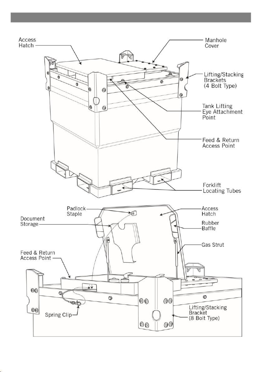
Unlock or unclip the access hatch, then open fully until it is held
open by the gas struts. Unscrew and remove the 3in male
nipple open filler cap and if not retained by a security chain,
place somewhere safe and clean.
Fill the IBC manually do not hard couple to the supply tank.
NOTE; The maximum quantity of fuel the IBC may be filled with is 95% of the IBC’s capacity.
Refer to the specification section for exact quantity for the model IBC you have.
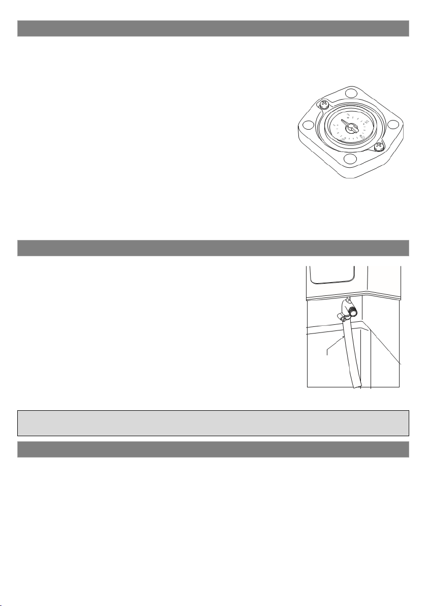
Observe the fuel level gauge for an indication of tank capacity then once filled, replace the
filler cap and clean up any fuel spillages.
BUND MAINTENANCE
The IBC bund area safeguards against any spillage exiting the
unit and polluting the immediate area. The bund is designed to
retain up to 110% of the unit’s maximum storage capability.
Though it is of a high capacity, any fuel entering the bund area
should be attended to as soon as possible without allowing the
quantity to simply increase.
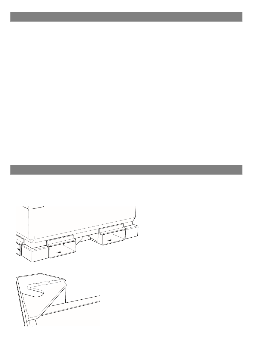
The bund should be kept empty as much as possible and should
the need arise to empty it, there is a bund emptying pipe fitted
within the bund area.
Fitted to the front right hand side of the unit, under the access
hatch, simply connect a suitable pump to the captive fitting and
empty into a waste container.
WARNING
Waste may only be collected by a registered carrier.
SPILLAGES
Should a spillage occur when emptying the bund, or when filling or transferring fuel, clear
the spillage as quickly as possible using absorbent material. Ideally, you should use a
dedicated spillage kit which will contain all the necessary items to retain and remove such a
spillage.
DO NOT hose the area down or use any detergents. DO NOT allow the fuel to enter drains
or water courses.
Spillages must be reported to the environment Agency Hot Line (0800 807 060).
All material used to retain and remove a spillage should be bagged and collected by a
registered carrier.

10
STATUTORY INSPECTION AND MAINTENANCE
It is a legal requirement that the owner of the IBC carries out regular inspections and
ensures that a record of each inspection is kept. Where fault is found, the unit MUST be
removed from service until the fault is rectified and the unit is retested successfully.
NOTE; Repairs may only be carried out by an authorised and certified agent.
Daily
Check the general condition of the IBC and all warning signage.
Check all pipe work and connections for security and leakage.
Inspect the bund area for collected fuel.
Monthly
As weekly with the addition of…
Clean and lubricate as necessary the access hatch hinges and gas struts.
Condition of the ground that the IBC is placed upon paying attention to possible ground
subsidence.
Every 2 ½ years
General external inspection, checking for corrosion, general damage and cracks in both
steel plating and welds.
The correct operation and function of all services, connections and fittings. Paying special
attention to the possibility of fuel leakage from joints and damaged hoses or pipes.
Leakproofness Test. The main tank must be tested for leakage. The tank must be capable of
retaining 20Kpa pressure for a minimum of 10 minutes.
Every 5 years (sooner if the bund area shows signs of filling without known cause).
An internal inspection of the main tank is required and for this, the tank must be removed
from the bund.
Inner tank removal
Before carrying out this procedure, make sure that you have the correct tools for the task, a
set of four x M22 lifting eyes and a set of lifting chains. Note that when the lift is performed,
the tank MUST remain level. It may also be prudent to remove any pipework or pump
systems that may get in the way when raising or replacing the tank within the bund.
Firstly, fit the four M22 lifting eyes to the four captive sockets on the top of the tank.
Next, using a pump connected to a piece of tube, insert the tube into the tank via
connection point numbered 1 or 2. Fully drain the tank, ensuring that the fuel being
removed is transferred into a suitable container. It is advisable to carry out a cleaning
programme on the internal tank at this stage to aid internal inspection.
Once the tank is completely emptied, mark each corner bracket and each side tank clasp so
that they can be replaced in exactly the same position.
Loosen and remove the four (or eight depending upon which model you have) corner
bracket retaining bolts (M12). Make sure you have a firm hold of the bracket as you remove
the last bolt to prevent it from dropping to the ground.
Repeat this with the remaining three corner brackets and place the brackets and bolts in a
safe place.
Now loosen the retaining bolts and remove each of the end and side tank clasps placing
them with the corner brackets. The tank is now ready to be lifted from the bund tank.

11
Attach suitable chain sling to the four lifting
eyes, adjusting as necessary to keep the tank
level. Lower the tank on to suitable supports
such as timber, to protect the base from
damage. To inspect the tank fully, loosen and
remove the bolts securing the manhole cover,
then remove the cover and gasket. The tank
can be inspected without the need for anyone
to enter the tank.
Once the inspection is complete, make sure
that all details of the inspection are written on
to the inspection record card.
Replace the manhole cover using a new gasket
and tighten the retaining bolts to 87Nm.
Carefully lower the tank back into the bund making sure that you keep everything correctly
aligned. Allow the lifting equipment to take the weight of the tank until each corner
brackets and each side tank clasp has been replaced and secured with their respective
bolts. All securing bolts should be tightened to 87Nm.
Remove the M22 lifting eyes to safeguard anyone mistaking them for the main lifting points
for the IBC. Finally, perform a leakproofness test before placing the IBC back in service.
ENVIRONMENTAL RESPONSIBILITY
Please refer to Environment Agency doc PPG7, available to download free from:
http://www.environment-agency.gov.uk
Correct and considerate management of diesel, its storage and transfer is the responsibility
of everyone who operates or maintains this equipment. All necessary precautions should be
made to prevent spillages and subsequently pollution of the environment.
Have in place a clear action plan to deal with accidental spillages, no matter how small or
large. Ensure that you have a diesel spillage containment kit available and that you
understand its correct use.
If a large spillage occurs, contact the environment agency for immediate advice.
DISPENSING FUEL
There are two options available for dispensing/supplying fuel. Either manually via a fuel
pump and nozzle or by direct coupling to the equipment such as a generator.
By Fuel Pump
Please refer to the documentation/instructions supplied with this unit for the correct
information covering the pump system you have fitted to this IBC
Direct Coupling
Direct coupling enables continuous fuel feed to equipment such as generators where power
is required continuously. Western Global can supply ¼”, ½” and ¾” feed and return hoses,
complete with quick release couplings.
Please contact Western Global for further information.

12
DISPOSAL
When maintaining, servicing or disposing of the IBC or consumable components, do not
dispose of contaminated parts within general refuse.
Refer to local authority regulations for their correct disposal.
MODIFICATIONS
If additional equipment or any third party work, modifications or alterations are to be
carried out on the IBC which will involve any welding, drilling or any form of cutting or
distortion of materials, full written approval must be obtained from the Manufacturer prior
to the work being carried out.

13
05TCG-EU SPECIFICATION SHEET

14
05TCG-EU GA DRAWING

15
05TCG-EU CERTIFICATE OF CONFORMITY

16
10TCG-EU SPECIFICATION SHEET

17
10TCG-EU GA DRAWING

18
10TCG-EU CERTIFICATE OF CONFORMITY

19
20TCG-EU SPECIFICATION SHEET
This manual suits for next models
3
Table of contents
Other Western Global Industrial Equipment manuals
Popular Industrial Equipment manuals by other brands

TOYOTA ADVANCED LOGISTICS
TOYOTA ADVANCED LOGISTICS Bastian SOLUTIONS Shoe Sorter Installation and maintenance manual

Vimpex
Vimpex hydrosense IDAP-S-2-230 installation instructions

ESAB
ESAB Tweco OCIM RB25T instruction manual

ITRON
ITRON EverBlu / RF Mounting and operation instructions

Siemens
Siemens 3VF9721-1 10 Series operating instructions

MRMC
MRMC MILO MRMC-2125-00 quick start guide