Western DEFENDER User manual

October 15, 2019
Lit. No. 72451, Rev. 03
This manual supersedes all editions with an earlier date.
DEFENDER™ Compact Plow
Owner's Manual
Original Instructions
A DIVISION OF DOUGLAS DYNAMICS, LLC
CAUTION
Read this document before operating or
servicing snowplow.
Western Products, PO Box 245038, Milwaukee, WI 53224‑9538 • www.westernplows.com


Lit. No. 72451, Rev. 03 3 October 15, 2019
OWNER INFORMATION
Register your snowplow online at www.westernplows.com
Owner Name: ______________________________________________________________________________
Date Purchased: ____________________________________________________________________________
Dealer Name: ______________________________________________ Phone: _________________________
Dealer Address:_____________________________________________________________________________
Vehicle Model/Year: _________________________________________________________________________
Snowplow Model/Year: _______________________________________________________________________
Snowplow Type/Size: ______________________________________________ Weight: ______________ lb/kg
Ballast: No ___ Yes ___ Amount: ___________lb/kg
Hydraulic Unit Serial Number: __________________________________________________________________
Blade Serial Number: ________________________________________________________________________

Lit. No. 72451, Rev. 03 4 October 15, 2019

Lit. No. 72451, Rev. 03 5 October 15, 2019
TABLE OF CONTENTS
PREFACE................................................................... 6
SAFETY ..................................................................... 7
Safety Denitions.................................................. 7
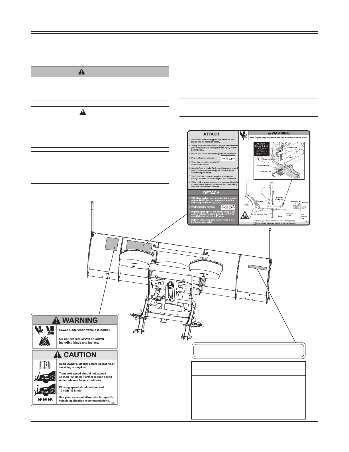
Warning/Caution and Instruction Labels .............. 7
Safety Precautions................................................ 8
Hydraulic Safety.................................................... 8
Fuses .................................................................... 8
Personal Safety..................................................... 9
Fire and Explosion ................................................ 9
Cell Phones........................................................... 9
Ventilation ............................................................. 9
Battery Safety ....................................................... 9
Noise..................................................................... 9
Vibration................................................................ 9
Snowplow Weight ................................................. 9
VEHICLE APPLICATION INFORMATION ........... 10
GETTING TO KNOW YOUR SNOWPLOW .......... 11
Snowplow Components ...................................... 11
Vehicle Mount Kit ................................................ 11
Snowplow Headlamps ........................................ 11
Hydraulic Unit...................................................... 12
System Capacity .......................................... 12
Cab Controls....................................................... 12
MOUNTING SNOWPLOW TO VEHICLE.............. 13
OPERATING YOUR SNOWPLOW ........................ 14
Hand-Held Control.............................................. 14
Joystick Control................................................... 15
SECURITY GUARD™ System ........................... 17
Smooth Stop ....................................................... 19
One-Touch Float ................................................. 19
Blade Positions ................................................... 20
Snowplow Headlamp Check............................... 20
Blade Drop Speed Adjustment ........................... 21
Transporting the Snowplow ................................ 21
Driving and Plowing on Snow and Ice ................22
Plowing Snow .....................................................22
Parking with Snowplow Attached ....................... 24
Towing a Disabled or Stuck Vehicle.................... 24
Checking Hydraulic Fluid Level........................... 24
DETACHING SNOWPLOW FROM VEHICLE ...... 25
MAINTENANCE ...................................................... 26
Maintenance Videos ........................................... 26
Preseason Check................................................ 26
In-Season Maintenance...................................... 26
Postseason Maintenance.................................... 26
Storage ...............................................................26
Aiming Headlamp Beams ................................... 27
Changing Plow-Edge Illumination Mode............. 28
Hydraulic System ................................................29
Annual Fluid Change.................................... 29
Hose or Fitting Replacement........................30
Procedure for Installing Fittings and Hoses ..30
Fuse Replacement.............................................. 31
Snowplow Vehicle Battery Best Practices .......... 31
Vehicle ................................................................ 31
Recycle ............................................................... 31
Emergency Parts/Tools ...................................... 31

Lit. No. 72451, Rev. 03 6 October 15, 2019
This manual has been prepared to acquaint you with
the safety information, operation, and maintenance of
your new snowplow. Please read this manual carefully
and follow all recommendations.
Before installing a snowplow, make sure that your
vehicle is equipped with our recommended options
for plowing snow. This will help ensure trouble-free
operation of your snowplow. Keep this manual
accessible. It is a handy reference in case minor
service is required.
PREFACE
When service is necessary, bring your snowplow to
your local outlet. They know your snowplow best and
are interested in your complete satisfaction.
The illustrations found in this manual represent
typical components. They may not match your exact
installation.

Lit. No. 72451, Rev. 03 7 October 15, 2019
SAFETY
Instruction Label
SAFETY DEFINITIONS
NOTE: Indicates a situation or action that can
lead to damage to your snowplow and vehicle or
other property. Other useful information can also
be described.
CAUTION
Indicates a potentially hazardous situation
that, if not avoided, may result in minor or
moderate injury. It may also be used to alert
against unsafe practices.
WARNING/CAUTION AND
INSTRUCTION LABELS
Become familiar with and inform users about the
warning/caution, serial number, and instruction labels
on the back of the blade.
NOTE: If labels are missing or cannot be read, see
your sales outlet.
WARNING
Indicates a potentially hazardous situation
that, if not avoided, could result in death or
serious personal injury.
Warning/Caution Label
Serial Number Label
Serial No.
Code Denition
YY 2-Digit Year
MM 2-Digit Month
DD 2-Digit Day
LL 2-Digit Location Code
XXXX 4-Digit Sequential Number
ZZZZZZ 5- to 7-Digit Blade Assembly PN
YYMMDDLLXXXXZZZZZ
ZZZZZ
zzzzz YYMMDDLLXXXXZZZZZ

Lit. No. 72451, Rev. 03 8 October 15, 2019
SAFETY
HYDRAULIC SAFETY
• Always inspect hydraulic components and hoses
before using. Replace any damaged or worn parts
immediately.
• If you suspect a hose leak, DO NOT use your hand
to locate it. Use a piece of cardboard or wood.
FUSES
The electrical and hydraulic systems contain several
automotive-style fuses. If a problem should occur
and fuse replacement is necessary, the replacement
fuse must be of the same type and amperage rating
as the original. Installing a fuse with a higher rating
can damage the system and could start a re.
Fuse Replacement, including fuse ratings and
locations, is located in the Maintenance section of
this Owner's Manual.
SAFETY PRECAUTIONS
Follow all safety and operating instructions in
your vehicle owner's manual.
Improper installation and operation could cause
personal injury, and/or equipment and property damage.
Read and understand labels and this Owner's Manual
before installing, operating, or making adjustments.
WARNING
Lower the blade when the vehicle is parked.
Temperature changes could change
hydraulic pressure, causing the blade to
drop unexpectedly or damaging hydraulic
components. Failure to do this could result in
serious personal injury.
WARNING
Remove blade assembly before placing
vehicle on hoist.
WARNING
The driver shall keep bystanders clear of the
blade when it is being raised, lowered, or
angled. Do not stand between the vehicle and
the blade or within 8 feet of a moving blade. A
moving or falling blade could cause personal
injury.
WARNING
To prevent accidental movement of the blade,
always turn the control OFF whenever the
snowplow is not in use. The power indicator
light will turn OFF.
WARNING
Keep hands and feet clear of the blade and
A‑frame when mounting or removing the
snowplow. Moving or falling assemblies could
cause personal injury.
WARNING
Hydraulic uid under pressure can
cause skin injection injury. If you are
injured by hydraulic uid, get medical
attention immediately.
WARNING
Do not exceed GVWR, GAWR, or
maximum vehicle load capacity,
including the blade and ballast.

Lit. No. 72451, Rev. 03 9 October 15, 2019
VENTILATION
BATTERY SAFETY
NOISE
Airborne noise emission during use is below 70 dB(A)
for the snowplow operator.
VIBRATION
Operating snowplow vibration does not exceed 2.5 m/s2
to the hand-arm or 0.5 m/s2to the whole body.
SNOWPLOW WEIGHT
Size Blade Assembly Wt (lb) Wt (kg)
6'8" DEFENDER™ Compact Plow 290 132
7'2" DEFENDER Compact Plow 297 135
PERSONAL SAFETY
• Remove the ignition key and put the vehicle in
PARK or in gear to prevent others from starting
the vehicle during installation or service.
• Wear only snug-tting clothing while working on
your vehicle or snowplow.
• Do not wear jewelry or a necktie, and secure
long hair.
• Wear safety goggles to protect your eyes from
battery acid, gasoline, dirt, and dust.
• Wear hearing protection such as earmus or
earplugs as appropriate or required.
• Avoid touching hot surfaces such as the engine,
radiator, hoses, and exhaust pipes.
• Always have a re extinguisher rated BC handy for
ammable liquids and electrical res.
FIRE AND EXPLOSION
Be careful when using gasoline. Do not use gasoline
to clean parts. Store only in approved containers away
from sources of heat or ame.
CELL PHONES
A driver's rst responsibility is the safe operation of the
vehicle. The most important thing you can do to prevent
a crash is to avoid distractions and pay attention to
the surroundings. Wait until it is safe to operate Mobile
Communication Equipment such as cell phones,
text messaging devices, pagers, or two-way radios.
SAFETY
CAUTION
Batteries normally produce explosive gases
which can cause personal injury. Therefore,
do not allow ames, sparks, or lit tobacco
to come near the battery. When charging or
working near a battery, always cover your
face and protect your eyes, and also provide
ventilation.
• Batteries contain sulfuric acid, which burns
skin, eyes, and clothing.
• Disconnect the battery before removing or
replacing any electrical components.
WARNING
Vehicle exhaust contains lethal fumes. Breathing
these fumes, even in low concentrations,
can cause death. Never operate a vehicle in
an enclosed area without venting exhaust to
the outside.
WARNING
Gasoline is highly ammable, and gasoline
vapor is explosive. Never smoke while
working on vehicle. Keep all open ames
away from gasoline tank and lines. Wipe up
any spilled gasoline immediately.

Lit. No. 72451, Rev. 03 10 October 15, 2019
Vehicle application recommendations are based on
the following:
• The vehicle with the snowplow installed must
comply with applicable Federal Motor Vehicle
Safety Standards (FMVSS).
• The vehicle with the snowplow installed must
comply with the vehicle manufacturer's stated
gross vehicle and axle weight ratings (found on
the driver-side door cornerpost of the vehicle) and
the front and rear weight distribution ratio. In some
cases, rear ballast may be required to comply with
these requirements. See "Ballast Requirements"
later in this section.
• The WESTERN Quick Match selection system is
based on available vehicle capacity for snowplow
equipment on a representative vehicle equipped
with options commonly used for plowing and with
300 lb of front seat occupant weight.
• Weights of front seat occupants can be adjusted
above 300 lb, but vehicle with snowplow must not
exceed vehicle GVWR or GAWR.
• In some cases there may be additional limitations
and requirements.
• Installation, modication, and addition of
accessories must comply with published
WESTERN recommendations and instructions.
Available capacity decreases as the vehicle is
loaded with cargo or other truck equipment, or
snowplow accessories are installed.
• If there is uncertainty as to whether available
capacity exists, the actual vehicle as congured
must be weighed.
BALLAST REQUIREMENTS
Ballast (additional weight) is an important part of
qualifying vehicles for snowplow eligibility. Rear
ballast must be used when necessary to remain in
compliance with axle ratings and ratios as specied
by the vehicle manufacturer. If ballast is required, it is
important that it be secured properly behind the rear
axle. A ballast retainer kit (PN 62849) is available from
your WESTERN outlet.
NOTE: The ballast retainer kit is for snowplow
vehicles requiring ballast. See your WESTERN
outlet for the correct amount of ballast required.
Include the weight of the retainer as part of the
ballast requirement. Sand bags are recommended
for use as ballast.
NOTE: Ballast recommended and its weight
calculations assume the entire width of the bed is
lled as close to tailgate as possible.
CAUTION
See your WESTERN®outlet/website for
specic vehicle application recommendations
before installation. The Quick Match selection
system has specic vehicle and snowplow
requirements.
Position
and secure ballast
as close to the tailgate
as possible.
VEHICLE APPLICATION INFORMATION

Lit. No. 72451, Rev. 03 11 October 15, 2019
Blad
e
Guid
e
Blade
Cutting
Edge
Hydraulic Unit
and Cover
Trip Spring
A-Frame
Headgear
Stand
Receiver
Assembly
Lift
Ram
Snowplow
Headlamps
GETTING TO KNOW YOUR SNOWPLOW
SNOWPLOW COMPONENTS
A snowplow consists of all the components that are
readily removable from the vehicle as a unit. This
includes the blade, A‑frame, headgear, hydraulic unit,
and snowplow headlamps. The snowplow is ready and
easy to mount when you need to plow snow. When
plowing is completed, remove the snowplow.
VEHICLE MOUNT KIT
Mount kits have been designed for most vehicles. Due
to the dierences among vehicle models, the kits are
not interchangeable.
The vehicle mount assembly is bolted to the underside
of the vehicle frame, and the receiver assembly is
attached to the vehicle mount. It is engineered to
provide the primary connecting points between the
snowplow assembly and the vehicle. The weight of the
snowplow system is distributed to the frame of your
vehicle by the mount assembly.
SNOWPLOW HEADLAMPS
When the electrical plugs are connected, the vehicle
headlamps will automatically switch to the snowplow
headlamps when they are turned ON. When the
electrical plugs are disconnected, the headlamps will
automatically switch to vehicle headlamps when they
are turned ON.
Replacement parts are available through your local
WESTERN®outlet.
NIGHTHAWK™ Snowplow Headlamps
The NIGHTHAWK snowplow headlamps consist
of a set of dual‑beam halogen headlamps plus
combination park and turn signals. A pre‑wired
harness with a plug‑in module requires no headlamp
wire splicing. The headlamps conform to Federal Motor
Vehicle Safety Standards (FMVSS).
NIGHTHAWK™ LED Snowplow Headlamps
with EdgeView™ Technology
The NIGHTHAWK LED snowplow headlamps with
EdgeView technology are rectangular solid‑optic LED
headlamps with focused low beams and high beams,
combination daytime running lamp (DRL) and
park/turn lights, and blade‑edge illumination. A
pre‑wired harness and headlamp control module
require no headlamp wire splicing. EdgeView
technology oers three choices for blade-edge
illumination. The headlamps conform to Federal Motor
Vehicle Safety Standards (FMVSS).
WARNING
Your vehicle must be equipped with snowplow
headlamps and directional lights.

Lit. No. 72451, Rev. 03 12 October 15, 2019
HYDRAULIC UNIT
The hydraulic system gives you full control of the
snowplow from the driver's seat. Two single-acting
hydraulic rams hold the blade at the desired angle.
The hydraulic unit's manifold has built-in blade scrape
lock circuitry. This feature resists the tendency of a
snowplow to "oat up" when large amounts of snow
build up in front of the blade while plowing deep snow
or stacking snow into piles.
The scrape lock feature is factory set. See your sales
outlet for adjustment.
System Capacity
• Unit Reservoir ............................... 1-3/4 quarts
• System Total ................................ 2-1/8 quarts
12V DC with +/– Connection
1750 psi Pump Relief Valve
4000 psi Angle Relief
3.0" dia 2.8 kW Motor (1.39 hp)
0.000476 gal/rev Pump
Hydraulic Hose SAE 100R1
GETTING TO KNOW YOUR SNOWPLOW
CAB CONTROLS
The controls are electrically powered through the
ignition (key) switch of your vehicle and are protected
by a replaceable in-line fuse. The ON/OFF switch
allows you to turn OFF the control and prevent blade
movement even when the ignition is ON.
The ON/OFF switch serves as an emergency stop
when required.
Quill
Breather/
Fill Plug
Motor
Reservoir
Drain
Plug
Valve
Manifold
WARNING
To prevent accidental movement of the blade,
always turn the control OFF whenever the
snowplow is not in use. The power indicator
light will turn OFF.
Power Indicato
r
Light (red)
Power Indicator
Light (red)
ON/OFF Button
(emergency stop)
ON/OFF Switch
(emergency stop)
Hand-Held Control
Joystick Control

Lit. No. 72451, Rev. 03 13 October 15, 2019
4. Plug in the electrical harness.
5. Turn the plow control in the vehicle ON and
activate FLOAT mode.
6. Stand in front of the blade. Push the top of the
headgear toward the vehicle to allow the connecting
pins to fully engage the connecting pin holes.
7. Verify that both connecting pins are engaged
through all holes on the headgear and receivers.
8. While holding the stand lock pin out, use the stand
handle to raise the stand. Release the stand lock
pin into the locking hole and verify that the stand
is secure.
ATTACHING THE SNOWPLOW
NOTE: The blade must be in the straight position
when attaching or detaching the snowplow.
NOTE: Use dielectric grease on all connections to
prevent corrosion.
NOTE: Use lubricant on connecting pins to ensure
ease of attach/detach.
1. Verify that both connecting pins are pulled out and
locked into the receiver notch.
2. Slowly drive the vehicle forward to engage the
rear receiver pins completely into the headgear
slots. Apply the vehicle parking brake.
3. Rotate and unlock the connecting pins on the
receivers.
WARNING
Inspect snowplow components and fasteners
for wear or damage whenever attaching or
detaching the snowplow. Worn or damaged
components could allow the snowplow to
drop unexpectedly.
WARNING
Keep 8' clear of the blade when it is being
raised, lowered, or angled. Do not stand
between vehicle and blade or directly in front
of the blade. If the blade hits or drops on you,
you could be seriously injured.
WARNING
Keep ngers away from snowplow and truck
attachment points.
MOUNTING SNOWPLOW TO VEHICLE
Blad
e
Stand
Connecting
Pin
Receiver
Headgear
Slot
Rear
Receiver
Pin
Locking
Hole
Connecting
Pin Hole
Stand Handle
Stand
Stand
Lock Pin
Receiver Notch
Connecting Pin

Lit. No. 72451, Rev. 03 14 October 15, 2019
HAND‑HELD CONTROL
1. Turn the vehicle ignition switch to the "ON" or
"ACCESSORY" position.
2. Press the ON/OFF button on the control. The
power indicator light glows red, indicating that the
control is ON. The power indicator light glows red
whenever the control and vehicle ignition switch
are both ON and the electrical connections to the
snowplow are completed.
The ON/OFF button operates as an emergency
stop, if required.
Function Time‑Outs
To limit the amount of electrical energy required
from the vehicle, all control functions, except
LOWER/FLOAT, time out (stop) automatically after a
period of time. The blade will coast to a stop.
NOTE: If a control function times out before the
desired blade movement is complete, release the
button and press it again.
WARNING
To prevent accidental movement of the blade,
always push the ON/OFF button to switch the
control OFF whenever the snowplow is not in
use. The power indicator light will turn OFF.
Optional Control Features
The control ships from the factory with the Smooth Stop
feature enabled and the One-Touch FLOAT feature
disabled. To change these default settings, see
"Smooth Stop" and "One-Touch FLOAT" later in this
section of the Owner's Manual.
Automatic Shutdown
The control will automatically turn OFF after being
idle for 20 minutes. To reactivate the control after a
shutdown, press the ON/OFF button.
Hand‑Held Control Functions
Raise, Lower, Float, Angle
The four diamond-shaped buttons in the center of the
control face, when pressed, will result in the blade
movements described in the following table.
Function Description of Operation
RAISE
Press this button to raise the blade and cancel
the FLOAT mode. Function times out after
4.0 seconds.
LOWER Press this button to lower the blade. Release
the button to stop blade at the desired height.
FLOAT†
Press the LOWER button and hold 3/4 second
to activate this mode. The FLOAT light in
the upper left corner of the control face will
illuminate. The blade will lower to the ground
surface and follow the contour of the surface
as it dips or rises. This function does not
time out, but the control will shut down after
20 minutes of nonuse.
Press the RAISE button momentarily to
cancel FLOAT. Angling left or right will not
interrupt (pause) the FLOAT function.
L
(Angle
Left)
Press the Lbutton to angle the blade left.
Function times out after 3.0 seconds.
R
(Angle
Right)
Press the Rbutton to angle the blade right.
Function times out after 3.0 seconds.
†FLOAT mode activates immediately when the one-touch FLOAT
feature is enabled. See "One-Touch FLOAT" later in this section
for more information.
RAISE
LOWER
R
L
ON/OFFFLOAT
1
43
2
ON/OFF Button
(emergency stop)
FLOA
T Light (green)
Power Indicator Light (red)
Hand-Held Control
OPERATING YOUR SNOWPLOW

Lit. No. 72451, Rev. 03 15 October 15, 2019
OPERATING YOUR SNOWPLOW
JOYSTICK CONTROL
1. Turn the vehicle ignition switch to the "ON" or
"ACCESSORY" position.
2. Move the ON/OFF switch on the side of the control
to the "ON" position. The power indicator light glows
red, indicating that the control is ON. The indicator
light glows red whenever the control and the vehicle
ignition switch are both ON and the electrical
connections to the snowplow are completed.
The ON/OFF switch operates as an emergency
stop if required.
WARNING
To prevent accidental movement of the blade,
always move the ON/OFF switch to OFF
whenever the snowplow is not in use. The
power indicator light will turn OFF.
Function Time‑Outs
To limit the amount of electrical energy required
from the vehicle, all control functions, except
LOWER/FLOAT, time out (stop) automatically after a
period of time. The blade will coast to a stop.
NOTE: If a control function times out before the
desired blade movement is complete, release the
lever to the center position, then move it back into
the desired function.
Optional Control Features
The control ships from the factory with the Smooth Stop
feature enabled and the One-Touch FLOAT feature
disabled. To change these default settings, see
"Smooth Stop" and "One-Touch FLOAT" later in this
section of the Owner's Manual.
Automatic Shutdown
The control will automatically turn OFF after being
idle for 20 minutes. To reactivate the control after a
shutdown, move the ON/OFF switch to OFF, then
back to ON.
Control Lever Movement
From the center position, the control lever can be
moved in one of eight directions to control various
movements of the snowplow blade. To change from
one blade movement to another, the control lever must
be moved back to the center position before selecting
the next desired function. Whenever the lever is
released, it should spring back into the center position
to stop any blade movement.
L R
RAISE
LOWER
ON/OFF FLOAT
12
34
Joystick Control
Power Indicator
Light (red)
ON/OFF Switch
(e
mergency stop)

Lit. No. 72451, Rev. 03 16 October 15, 2019
OPERATING YOUR SNOWPLOW
Joystick Control Functions
Raise, Lower, Float, Angle
Moving the control lever straight up and down or from
side to side on the control body will result in the blade
movements described in the following table.
Function Description of Operation
RAISE
Move the control lever toward the top of the
control body to raise the blade and cancel
the FLOAT mode. Function times out after
4.0 seconds.
LOWER
Move the control lever toward the bottom of
the control body to lower the blade. Release
the lever to stop blade at the desired height.
FLOAT†
Move the control lever to the LOWER position
and hold 3/4 second to activate this mode.
The FLOAT light in the upper left corner of
the control face will illuminate. The blade will
lower to the ground surface and follow the
contour of the surface as it dips or rises. This
function does not time out, but the control will
shut down after 20 minutes of nonuse.
Move the lever to the RAISE position
momentarily to cancel FLOAT. Angling left
or right will not interrupt (pause) the FLOAT
function.
L
(Angle
Left)
Move the control lever straight to the left to
angle the blade left. Function times out after
3.0 seconds.
R
(Angle
Right)
Move the control lever straight to the right to
angle the blade right. Function times out after
3.0 seconds.
†FLOAT mode activates immediately when the one-touch FLOAT
feature is enabled. See "One-Touch FLOAT" later in this section
for more information.
NOTE: If a control function times out before the
desired blade movement is complete, release the
lever to the center position, then move it back into
the desired function.

Lit. No. 72451, Rev. 03 17 October 15, 2019
OPERATING YOUR SNOWPLOW
SECURITY GUARD™ SYSTEM
Activation & Establishing a 4‑Digit
Security Code
NOTE: Snowplow must be attached to vehicle,
and all electrical connections must be connected
prior to activating the security code function.
The SECURITY GUARD feature was developed as
an electrical anti-theft system. The system provides
a deterrent against theft and/or non-permitted use
by allowing you to electronically lock the snowplow's
hydraulic functions.
All multiplex snowplow controls come equipped with
the SECURITY GUARD system. To use this function,
you must complete the activation process.
1. Turn the vehicle ignition switch to the "ON" or
"ACCESSORY" position. (It is not necessary to
start the vehicle.)
2. Verify that the control power indicator is OFF. If
the power indicator light is red, the control is ON.
Move the ON/OFF switch to "OFF" or push the
ON/OFF button to turn the control OFF.
3. To activate the SECURITY GUARD mode, move
the control lever to the #1 position or press the #1
button four consecutive times, and then move the
lever to the #4 position or press the #4 button four
consecutive times (sequence: 1, 1, 1, 1, 4, 4, 4, 4).
The green FLOAT light will ash quickly and the
red power indicator light will turn ON, indicating
that the system is ready to accept your 4-digit
security code.
4. Enter your 4-digit security code by moving the
control lever to (or pressing the button for) any four
of the eight positions: UP, DOWN, LEFT, RIGHT,
1, 2, 3, or 4.
5. After you have entered your 4-digit security code,
the FLOAT light will stop ashing and the power
indicator light will turn OFF. This indicates that
your 4-digit security code is entered and stored in
the SECURITY GUARD system.
NOTE: If the control is turned ON prior to
completing the programming procedure, your
4‑digit security code will be cancelled.
Once a 4-digit security code is established, the
SECURITY GUARD system will recognize any control
that has been programmed with the same 4-digit
security code. If a control not programmed with the
correct 4-digit code is connected to the system, the
established security code will have to be entered
manually before the snowplow can be activated (see
the Manual Unlock Procedure below).
Manual Unlock Procedure
If the SECURITY GUARD system is activated and you
are using a control with a dierent 4-digit code than
the established security code, you will be required
to manually enter the 4-digit security code before
operating a locked snowplow.
1. Turn the vehicle ignition to the "ON" or
"ACCESSORY" position.
2. Move the ON/OFF switch to the "ON" position
or push the ON/OFF button to switch the control
ON. The power indicator light will ash rapidly,
indicating that the snowplow is locked.
3. Enter the 4-digit security code.
4. After the correct security code is entered, the
power indicator light will change from ashing
rapidly to a solid light to indicate that the snowplow
has been successfully unlocked.
NOTE: If the plow/vehicle electrical connection
is lost or disconnected, the SECURITY GUARD
system will reset, requiring any control that is not
programmed with the established 4‑digit security
code to manually re‑enter the security code to
activate the snowplow.

Lit. No. 72451, Rev. 03 18 October 15, 2019
OPERATING YOUR SNOWPLOW
Clearing an Established 4‑Digit
Security Code
1. Turn the vehicle ignition switch to the "ON" or
"ACCESSORY" position.
2. If the snowplow is locked (the control power
indicator light will be ashing rapidly), unlock
the snowplow by following the Manual Unlock
Procedure described above.
3. Move the ON/OFF switch to the "OFF" position
or push the ON/OFF button to switch the control
OFF. Verify that the power indicator light is OFF.
With the control OFF, move the control lever
to the #2 position or press the #2 button four
consecutive times, then move the lever to
the #3 position or press the #3 button four
consecutive times. This sequence (2, 2, 2, 2,
3, 3, 3, 3) will clear the 4-digit security code from
the SECURITY GUARD™ system.
The FLOAT light will ash to indicate that the
security code was cleared.
NOTE: To enter a new 4‑digit security code, see
Activation & Establishing a 4‑Digit Security Code.
Light Flash Indicators
POWER – Red Function
OFF Control is OFF
Solid ON Control is ON and active
Slow Flash No communication
Fast Flash Snowplow is locked—enter 4-digit
security code to unlock
FLOAT – Green Function
Solid ON FLOAT function is active
Fast Flash Security code activation in progress
Additional Notes
• The SECURITY GUARD system requires any
control other than the one with the assigned
4-digit security code to enter the security
code before the snowplow can be activated.
Once the security code is established, the
SECURITY GUARD system recognizes when a
control with the same security code is attached
and does not require a manual unlock to activate
the snowplow. The system will recognize the
control as "safe" and will automatically unlock.
• In the event that a locked snowplow cannot
be manually unlocked or reset, contact your
authorized dealer.
• REMINDER: Record your security code for future
reference.

Lit. No. 72451, Rev. 03 19 October 15, 2019
OPERATING YOUR SNOWPLOW
SMOOTH STOP
Smooth stop, or soft stop, allows the blade to coast
to a stop when the button/lever is released. The
result is smoother operation, reduction in shock to the
hydraulic system, and longer hose and valve life.
While there are advantages to having this feature,
there are also advantages to temporarily disabling it.
For example, disabling smooth stop allows for more
precise movements of the blade while operating close
to buildings and other obstacles.
All controls come standard with this feature ENABLED.
To enable/disable smooth stop, perform the following
steps. Performing the sequence multiple times will
toggle the feature between enabled and disabled.
Enable/Disable Procedure
1. Turn the vehicle ignition switch to the "ON" or
"ACCESSORY" position. (It is not necessary to
start the vehicle.)
2. Verify that the control power indicator is OFF. If
the power indicator light is red, the control is ON.
Move the ON/OFF switch to "OFF" or push the
ON/OFF button to turn the control OFF.
3. Move and hold the control lever to the "R" position
or press and hold the R button while turning the
control ON. The power indicator light will turn ON
and the FLOAT light will ash, indicating the status
of the feature.
Light Flash Indicators
Light Description
POWER – Red Solid ON = Control is ON
FLOAT – Green 1 Flash = Smooth stop enabled
2 Flashes = Smooth stop disabled
ONE‑TOUCH FLOAT
One-touch FLOAT immediately activates the FLOAT
mode and releases the blade to the ground, without
having to hold the button or lever in LOWER. This
can improve transition time when backing up to plow
forward again, eliminating the time spent holding the
control and waiting for the blade to fully drop.
All controls come standard with this feature DISABLED.
To enable/disable this feature, perform the following
steps. Performing the sequence multiple times will
toggle the feature between enabled and disabled.
Enable/Disable Procedure
1. Turn the vehicle ignition switch to the "ON" or
"ACCESSORY" position. (It is not necessary to
start the vehicle.)
2. Verify that the control power indicator is OFF. If
the power indicator light is red, the control is ON.
Move the ON/OFF switch to "OFF" or push the
ON/OFF button to turn the control OFF.
3. Move and hold the control lever to the "LOWER"
position or press and hold the LOWER button
while turning the control ON. The power indicator
light will turn ON and the FLOAT light will ash,
indicating the status of the feature.
Light Flash Indicators
Light Description
POWER – Red Solid ON = Control is ON
FLOAT – Green
1 Flash = One-touch FLOAT disabled
2 Flashes = One-touch FLOAT
enabled

Lit. No. 72451, Rev. 03 20 October 15, 2019
BLADE POSITIONS
The compact plow can be used in these plowing
positions.
Straight Blade
Use straight blade for wide-path plowing or stacking
snow.
Angled Blade
Angle the blade right or left for general plowing
and widening.
OPERATING YOUR SNOWPLOW
SNOWPLOW HEADLAMP CHECK
With all electrical plugs connected, check the
operation of vehicle and snowplow headlamps.
Lights Results
Parking Lamps Both vehicle and snowplow lamps
should be ON.
Right Turn Signal Both vehicle and snowplow lamps
should be ON.
Left Turn Signal Both vehicle and snowplow lamps
should be ON.
Connecting and disconnecting the electrical plugs
should switch between the vehicle and snowplow
headlamps as follows:
• Electrical plugs DISCONNECTED—Vehicle
headlamps function normally.
• Electrical plugs CONNECTED—Vehicle headlamp
functions transfer to the snowplow headlamps.
On some DRL systems, both the vehicle and
snowplow headlamps will function.
Aiming the Headlamps
• Aim the snowplow headlamps with the snowplow
mounted and raised in the transport position. See
"Aiming Headlamp Beams" in the Maintenance
section for instructions.
• Aim the vehicle headlamps with the snowplow
removed from the vehicle.
Other manuals for DEFENDER
1
Table of contents
Other Western Snow Blower Accessories manuals