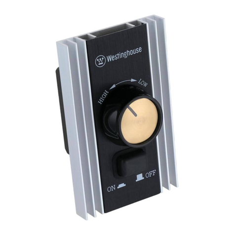
Westinghouse WH10 User manual

GS-MULTI-Fan-Light-WallControl-WH10
GB
Wall Control Installation and Operating Instructions
D Einbau- und Betriebsanleitung fürWandsteuerung
F Instructions d’installation et de fonctionnement pour la commande murale
E
Instrucciones para la instalación y modo de empleo del control de pared
CZ
Návod k nástěnnému ovládání
I
Istruzioni per l’installazione e il funzionamento del controllo a parete

GS-MULTI-Fan-Light-WallControl-WH10
GB
WARNING! SHUT POWER
OFF AT THE FUSE BOX OR CIRCUIT BREAKER.
SAFETY PRECAUTIONS:
1. WARNING: To
avoid fire, electrical shock and serious personal injury, follow all instructions carefully. Read your
Owner’s Manual carefully before installing this ceiling fan control. Retain the Owner’s Manual
for future reference.
2. To avoid personal electrical shock, make sure electricity is turned off at the main fuse box or circuit breaker panel before wiring.
3. This control is designed to operate only one ceiling fan and accessory light fixture. If
your ceiling fan is equipped with variable fan speed and ON/OFF light fixture
pull chain controls, make sure to set the fan speed control at the highest
fan speed, and the light fixture control to the
ON position prior to installing the wall control unit. This will avoid the chance of erratic speed and possible damage to your ceiling
fan.
4. After wiring, make certain no bare wires are exposed outside the connectors from the wall control unit.
5. All wiring must conform to National and Local Electrical Codes.
If you feel you do not have enough electrical wiring knowledge, or experience, have your wall control installed by a licensed electrician. Any electrical work not described in
this manual should be performed by a licensed electrician.
6. Use of this control with some ceiling fans could result in fire, electrical shock and serious personal injury. Use this fan wall control with capacitor speed controlled fans
only
.

GS-MULTI-Fan-Light-WallControl-WH10
D
ACHTUNG! UNTERBRECHEN SIE DIE STROMZUFUHR AM HAUPTSICHERUNGSKASTEN BZW. AN DER SICHERUNG DES
STROMKREISES
SICHERHEITSVORKEHRUNGEN:
1. VORSICHT:
Bitte halten Sie sich genau an die Anleitung, um Brand, Stromschläge und schwere Verletzungen zu vermeiden. Machen Sie sich mit der Bedienungsanleitung vertraut, bevor Sie mit der Installation dieser Steuerung für den
Deckenventilator beginnen. Bewahren Sie die Bedienungsanleitung auf, um später bei
Bedarf darauf zurückkehren zu können.
2. Um die Gefahr von Stromschlägen zu vermeiden, sollten Sie sich vor Beginn der Verkabelungsarbeiten vergewissern, dass die Stromzufuhr am Hauptsicherungskasten bzw. an der Sicherung des Stromkreises unterbrochen
ist.
3. Diese Steuerung ist nur zum Betrieb eines einzigen Deckenventilators und einer einzigen Lampe konzipiert. Falls Ihr Deckenventilator mit einer Geschwindigkeitsregelung und einer Ein/Aus-Zugkette an der Lampe ausgerüstet
ist,
sollten Sie sich vergewissern, dass die Geschwindigkeitsregelung auf die höchste Geschwindigkeit und die Zugkette an der Lampe auf die Position „ON“ (Ein) gestellt ist, bevor Sie mit dem Einbau der Wandsteuereinheit beginnen.
Dadurch wird die Gefahr plötzlich auftretender, hoher Geschwindigkeit und möglicher Beschädigung Ihres Deckenventilators
vermie
den.
4. Stellen Sie sicher, dass sich keine blanken Kabel außerhalb der zur Wandsteuereinheit gehörenden Kabelverbindungen befinden.
5. Sämtliche Kabelarbeiten müssen in Übereinstimmung mit den jeweils gültigen, örtlichen Vorschriften zur Arbeit an elektrischen Einrichtungen vorgenommen werden. Überlassen Sie die Installation der Ventilator-Wandsteuerung einem
zugelassenen Elektriker, falls Sie der Meinung sind, dass Sie nicht über ausreichendes Fachwissen oder Erfahrung verfügen. Sämtliche elektrische Arbeiten, die nicht in dieser Anleitung beschrieben sind, sollten einem zugelassenen
Elektriker überlassen werden.
6. Der Betrieb dieser Steuereinheit kann zu Feuer, Stromschlägen und schweren Verletzungen führen, wenn sie mit bestimmten Deckenventilatoren verwendet wird. Verwenden Sie diese Wandsteuerung nur mit Ventilatoren, deren
Geschwindigkeit kondensatorgesteuert
ist.

GS-MULTI-Fan-Light-WallControl-WH10
F
ATTENTION ! METTEZ L’INTERRUPTEUR DE LA BOITE A FUSIBLES OU DE DISJONCTEURS SUR « OFF
».
MESURES DE PRECAUTION :
1. ATTENTION : Afin d'éviter
les incendies, l’électrocution et les blessures corporelles, suivez attentivement toutes les instructions. Consultez votre guide d’utilisation avant de commencer l’installation de cette commande du
ventilateur
de plafond. Conservez le guide d’utilisation pour
future référence.
2. Afin d’éviter le risque d’électrocution, assurez-vous que l’alimentation électrique principale est coupée à la boîte de fusibles ou de disjoncteurs avant de passer aux raccordements.
3. Cette commande est conçue pour faire fonctionner un seul ventilateur de plafond et un élément d'éclairage. Si votre ventilateur de plafond est doté d'une chaîne permettant de contrôler les vitesses et d'allumer ou d'éteindre
l'élément
d'éclairage, assurez-vous de régler la vitesse au niveau le plus élevé et la lumière en position
ON,
avant d'installer la commande murale.
Ceci
évitera d'obtenir des vitesses irrégulières et peut-être d'endommager votre ventilateur de plafond.
4. Après avoir connecté les fils, assurez-vous qu’aucun fil nu ne dépasse des connecteurs de la commande murale.
5. Les câbles électriques doivent être conformes aux codes national et local d’électricité. Si vous croyez ne pas avoir suffisamment de connaissances ou d'expérience en matière d'électricité, faites installer votre commande
murale par
un électricien agréé. Tout travail d’électricité qui n’est pas décrit dans ce guide d’utilisation doit être réalisé par un électricien agréé.
6. L'utilisation de cet appareil de commande avec certains ventilateurs de plafond pourrait causer un incendie, un choc électrique et de graves blessures personnelles. Utilisez cette commande murale uniquement avec les
ventilateurs
de plafond dont la vitesse est commandée par un condensateur.

GS-MULTI-Fan-Light-WallControl-WH10
E
¡ADVERTENCIA! DESCONECTE EL SUMINISTRO DE ENERGÍA QUITANDO EL FUSIBLE O APAGANDO EL
COR
T
ACIRCUITO
PRECAUCIONES
DE SEGURIDAD:
1. ADVERTENCIA: Siga las instrucciones al pie de la letra para evitar incendios, choques eléctricos
y lesiones personales graves. Lea detenidamente el Manual del usuario antes de instalar este control para ventilador de techo.
Guarde
el
Manual del usuario para referencia
futura.
2. Para evitar choques eléctricos, asegúrese de desconectar la alimentación principal quitando el fusible o apagando el cortacircuito, antes de realizar el cableado.
3. Este control está previsto para operar un solo ventilador de techo y un juego de luces accesorio. Si el ventilador de
techo
está equipado con controles de velocidad variable
y
de ENCENDIDO/APAGADO con cadenilla de tiro para el juego de
luces,
ponga el control de velocidad en la velocidad más alta y
la lámpara en la posición de ENCENDIDO antes de instalar el control
de
pared. De esta manera evitará las velocidades erráticas y la posible avería de su ventilador de
techo.
4. Después de realizar el cableado, cerciórese de que ningún cable sin aislación quede fuera de los conectores de la unidad del control de pared.
5. Todo el cableado debe cumplir con los códigos eléctricos nacionales y locales. Si piensa que no tiene suficientes conocimientos o experiencia en cableado eléctrico, acuda a un electricista certificado para que le instale el control de
pared para ventiladores. Todo trabajo eléctrico que no se describe en este manual deberá ser realizado por un electricista certificado.
6. El empleo de este control podría causar incendio, choque eléctrico y lesiones personales graves cuando se utiliza para controlar algunos ventiladores de techo. Use este control de pared para ventiladores únicamente con
ventiladores de techo de velocidad controlada por condensador.

GS-MULTI-Fan-Light-WallControl-WH10
CZ
POZOR! ODPOJTE P
ŘÍVOD ELEKTRICKÉHO VEDENÍ.
.
BEZPEČNOSTNÍ OPAT
ŘENÍ
:
1. VAROVÁNÍ: Aby nedošlo k požáru, úrazu elektrickým proudem a vážnému zran
ění osob, dodržujte všechny pokyny. Pečlivě si přečtěte návod k obsluze ještě před instalací stropního ventilátoru a tohoto ovládání. Uschovejte tento návod pro pozdější použití.
2. Než začnete s instalací, ujist
ěte, že je vypnut přívod elektrického vedení, aby nedošlo ke zranění.
3. Toto ovládání je určeno k provozu pouze jednoho stropního ventilátoru. Pokud je Váš stropní ventilátor vybaven prom
ěnlivou rychlostí ventilátoru a řetízkovým ovládáním, nastavte otáčky ventilátoru na nejvyšší rychlost a regulaci osvětlení do
pozice ON ještě před instalací stropního ventilátoru. Tím zabráníte nevypočitatelné rychlosti a případnému poškození stropníh o ventilátoru.
4. Ujist
ěte se, zda nejsou nikde viditelné holé dráty,
5. Všechna zapojení musí odpovídat národním a místním elektrotechnickým p
ředpisům. Pokud máte pocit, že nemáte dostatek znalostí nebo zkušeností pro zapojení jednotky, obraťte se na oprávněného elektrikáře. Jakékoliv elektrickářské práce, které
nejsou popsány v tomto návodu by měl provádět pouze kvalifikovaný elektrikář.
6. Použítím tohoto ovládání s n
ěkterými stropními ventilátory může dojít k požáru, úrazu elektrickým proudem nebo vážnému zranění. Používejte proto tato ovládání pouze k příslušným stropním ventilátorům.

GS-MULTI-Fan-Light-WallControl-WH10
I
AVVERTENZA. SCOLLEGARE L’UNITÀ DALLA SCATOLA DEL FUSIBILE O DELL’INTERRUTTORE DI
SICUREZZA.
PRECAUZIONI
1. AVVERTENZA: attenersi a tutte le istruzioni onde evitare il rischio di incendio, scossa elettrica e lesioni personali. Leggere attentamente il Manuale dell’utente prima di installare il controllo del ventilatore da soffitto. Conservare
il
manuale per
riferimento futuro.
2. Prima di effettuare il cablaggio e al fine di evitare il rischio di scossa elettrica, assicurarsi di aver disattivato la corrente di rete alla scatola del fusibile principale o dell’interruttore di sicurezza.
3. Questo telecomando è inteso per l’uso esclusivamente con un solo ventilatore a soffitto e un lampadario accessorio. Se il ventilatore in dotazione è munito di un regolatore di velocità variabile e di una catenella per accendere e
spegnere la luce, accertarsi di impostare il controllo di velocità al massimo e di accendere la luce (posizione ON) prima di installare l’unità di controllo a parete. Tale accorgimento assicurerà una velocità costante e impedirà che
si
possano arrecare danni al
ventilatore.
4. Una volta effettuato il cablaggio, assicurarsi che non siano visibili fili nudi che fuoriescono dai connettori dell’unità di controllo a parete.
5. Il cablaggio deve essere eseguito in conformità ai codici elettrici nazionali e locali. Se non si ritiene di avere sufficiente dimestichezza o abilità con i collegamenti elettrici, affidare l’installazione del controllo a parete del
ventilatore
a
un elettricista competente. Tutti i cablaggi elettrici non descritti in questo manuale devono essere eseguiti soltanto da un elettricista competente.
6. L’uso di questo controllo con alcuni ventilatori da soffitto può creare il rischio di incendio, scossa elettrica e gravi infortuni. Utilizzare questo controllo a parete con una velocità di condensatore regolata esclusivamente dal
ventilatore.

GS-MULTI-Fan-Light-WallControl-WH10

GS-MULTI-Fan-Light-WallControl-WH10
GB
NOTE:
Installation of this control requires that the three-conductor cable with ground wire be run in between the control wall outlet box and the ceiling fan outlet
box.
D
HINWEIS: Zum Einbau dieser Steuereinheit gehört die Verlegung eines 3-fach Kabels mit Erdung zwischen der Dose der Wandsteuereinheit und der Dose am
Deckenventilator.
F
NOTE :
L’installation de cette commande exige que les trois fils conducteurs et le fil de mise à la terre passent entre la boîte murale de la commande et la boîte de sortie de courant du
ventilateur
.
E
NOTA: Para instalar este control se debe tender un cable de tres conductores con cable de tierra entre la caja de embutir del control
y la caja de embutir del ventilador de techo.
CZ
POZNÁMKA: Instalace tohoto ovládání vyžaduje t
ří – fázový vodičový kabel s uzemněním mezi krabičkou nástěnného ovládámí a krabičkou stropního ventilátoru.
I
NOTA:
l’installazione di questo controllo richiede l’uso di un cavo trifase (a 3 conduttori), in cui il filo di massa si collega dalla presa a parete del controllo alla spina del
ventilatore.

1GB
After electricity has been turned off at the main fuse box or circuit breaker panel, remove the existing wall plate and
switch.
GS-MULTI-Fan-Light-WallControl-WH10
D
Nachdem die Stromzufuhr am Hauptsicherungskasten bzw. an der Sicherung des Stromkreises unterbrochen ist, die bestehende Abdeckung des Wandschalters und den Schalter
entfernen.
F
Après avoir coupé l'alimentation électrique principale à la boîte de fusibles ou de disjoncteurs, retirez la plaque murale et
l’interrupteur
.
E
Una vez apagada la alimentación en la caja principal de fusibles o el panel del cortacircuito, saque la placa de pared
y el
interruptor
.
CZ
Poté, co jste odpojili p
řívod k elektrickému vedení, odstraňte kryt z ovládání a vypínače.
I
Dopo aver disattivato la corrente di rete alla scatola del fusibile principale o dell’interruttore di sicurezza, rimuovere la piastra e l’interruttore a
parete.

2GB
Proceed to make the wire connections following the next step. Make certain the fan and light switches on the wall control unit are set to the OFF
position.
D
Mit den dem nächsten Schritt folgenden Kabelverbindungen fortfahren. Vergewissern Sie sich, dass sich die Ventilator- und Lampenschalter an der Wandsteuereinheit auf „OFF“ (Aus)
befinden.
GS-MULTI-Fan-Light-WallControl-WH10
F
Effectuez les raccordements électriques selon l’étape suivante des instructions. Assurez-vous que les commutateurs du ventilateur et de l'élément d'éclairage sur la commande murale sont en position
OFF
.
E
Proceda con las conexiones de cableado siguiendo el próximo paso. Cerciórese de que los interruptores del ventilador
y
del juego de luces en la unidad de control de pared estén en la posición de
AP
AGADO.
CZ
Následující krok je p
řípojení drátu, ujistěte se, že vetnilátor a světlo na nástěnném ovládání je nastaveno do polohy OFF.
I
Effettuare i collegamenti dei cavi secondo le istruzioni sotto riportate. Assicurarsi che gli interruttori di azionamento del ventilatore e della luce dell’unità di controllo a parete siano in posizione
OFF
.

3
GB
Remove the front cover of the wall control GB by unsnapping the cover
(1) from the control unit
(2).
D
Die Abdeckplatte (1) der Wandsteuerung durch Ausrasten von der Steuereinheit (2)
entfernen.
GS-MULTI-Fan-Light-WallControl-WH10
1
2
F
Déposez le couvercle de la face avant du commutateur mural en déclipsant le couvercle (1) du commutateur
(2).
E
Retire la cubierta delantera del control de pared soltando la cubierta (1) de la unidad de control
(2).
CZ
Sejm
ěte pření kryt ovládání (1) z řídící jednotky (2).
I
Rimuovere la copertura anteriore del controllo a parete togliendo la copertura (1) dall'unità di controllo
(2).

4
3
GB
GS-MULTI-Fan-Light-WallControl-WH10
D
F
3
3
To LIGHT FAN TO
HOT
2
1
2
1
Connect
the fan
control w
i
r
e
from the fan, to the
t
e
r
m
i
na
l
marked
“
FAN”on the
ba
c
k
o
f
the wall control unit
(
1
)
.
Connect the light control
w
i
r
e
from the fan to the
t
e
r
m
i
na
l
marked
“
T
O
LIGHT”on
t
h
e
back of
the wall control
un
i
t
(2).
Connect the
230
V
h
o
t
house wire to the
“
T
O
H
O
T
”
terminal on the back
of
t
h
e
wall control unit
(3).
Se
c
u
r
e
t
h
e
wires by inserting the w
i
r
e
into the terminal
and
tightening with a s
c
r
ew
d
r
i
v
e
r
.
NOTE:
Refer to the
ill
u
s
tr
a
t
i
o
n
s
for
c
l
a
r
i
t
y
.
Das Ventilatorsteuerkabel vom
V
entilator
mit dem Anschluss„FAN“(zum
V
entilator)
auf der Rückseite der
W
andsteuereinheit
(1)
verbinden.
Das
Lampensteuerkabel
vom Ventilator mit dem Anschluss
„TO
LIGHT“(zur Lampe) auf der Rückseite
der Wandsteuereinheit (2) verbinden. Da
stromführende Installationskabel
(230 V/Wechselstrom) mit dem
Anschluss „TO HOT“
(zum Wechselstrom,
positiv) verbinden
auf der Rückseite der
W
andsteuereinheit
(3). Sichern Sie die Kabel, indem Sie sie
in die Anschlusseinheit einführen und
mit
einem Schraubenzieher festschrauben
HINWEIS: Siehe Abbildungen
für Details.
Branchez le
fil
de la commande du ventilateur à
l
a
position portant la mention «
FAN
» sur la b
o
î
t
e
de
c
o
nn
e
x
i
o
n
s
,
se trouvant sur la partie arrière
d
e
la commande murale
(1).
Branchez le
fil
de
l
a
commande de l’élément d’éclairage à la
p
os
i
t
i
o
n
portant la mention «
TO
LIGHT » sur la boîte
d
e
c
o
nn
e
x
i
o
n
s
,
se trouvant sur la partie arrière de
l
a
commande murale
(2).
Branchez le
fil
chargé
d
e
la résidence de 230 V à la position portant
l
a
mention «
TO HOT
» sur la boîte de
c
o
nn
e
x
i
o
n
s
sur
la partie arrière de la commande murale
(
3
)
.
Fixez
les
fils
en place en les
faisant
passer par
l
a
boîte de
c
o
nn
e
x
i
o
n
s
et serrez à l’aide
d
’
un
tournevis.
NOTE
: Reportez-vous
aux ill
u
s
tr
a
t
i
o
n
s
en cas de
d
o
u
t
e
.

GS-MULTI-Fan-Light-WallControl-WH10
E CZ I
Conecte el cable del control
d
e
l
ventilador del ventilador a la
t
e
r
m
i
na
l
marcada “FAN”
(
A
L
V
E
N
T
I
L
AD
O
R
)
en la parte posterior de la unidad
d
e
control de pared
(1).
Conecte el c
ab
l
e
del control del juego de luces
d
e
l
ventilador a la terminal ma
r
c
ada
“
T
O
LIGHT”
(
A
L
J
U
E
G
O
DE
L
U
C
E
S
)
en la parte posterior de la
un
i
dad
de control de pared
(2).
Conecte
e
l
cable vivo de 230 V de la casa
a
la terminal marcada “To
h
o
t
”
(
A
vivo de
C
A
)
en la parte posterior
d
e
la unidad de control de pared
(
3
)
.
Asegure los cables insertándolos
d
e
n
tr
o
de la terminal y ajustándolos con
un
destornillador.
NOTA:
Consulte
l
a
s
ilustraciones para
c
l
a
r
i
f
i
c
a
r
.
P
řipojte kabel ventiláutoru od ventilátoru
ke svorce označené “FAN” na zadní
straně řídící jednotky (1).
Připojte kabel světla od ventilátoru ke
svorce označené “TO LIGHT” na zadní
straně řídící jednotky (2).
Připojte kabel na 230V ke svorce
označené “TO HOT” na zadní straně řídící
jednotky (3).
Kabely uložte do krabičky a upevněte
pomocí šroubováku.
POZNÁMKA: Pro přehlednost viz.
obrázek
Collegare
il filo
del controllo
d
e
l
ventilatore al terminale “FAN”
p
os
t
o
sul retro dell’unità di controllo a
pa
r
e
t
e
(1).
Collegare
il filo
del controllo
d
e
ll
a
luce al terminale
“
T
O
LIGHT”posto s
u
l
retro dell’unità di controllo a parete
(
2
)
.
Collegare
il filo
della
rete elettrica a
230 V al terminale
“
T
O
H
O
T
”
posto sul retro dell’unità di controllo
a
parete
(3).
Fissare
i fili i
n
se
r
e
nd
o
li
ciascuno in un terminale e
a
vv
i
t
and
o
li
con un cacciavite.
NOTA:
f
a
r
e
riferimento
alle illustrazioni
p
e
r
maggiore
c
h
i
a
r
e
zz
a.

GS-MULTI-Fan-Light-WallControl-WH10
5
GB
Operation:
Fan Rotary Control
0
-
Fan Speed OFF
4 -
Fan Speed HIGH
3 -
Fan Speed MEDIUM HIGH
2 -
Fan Speed MEDIUM
1
-
Fan Speed LOW
Operation:
Light
Switch
Light
On
Light Off
D
Betrieb:
Geschwindigkeitskontrolledes
V
entilators
0 -
Geschwindigkeit Aus
4 -
Geschwindigkeit Hoch
3 -
Geschwindigkeit Mittel - Hoch
2 -
Geschwindigkeit
Mittel
1 -
Geschwindigkeit Niedrig
Betrieb:
Lichtschalter
Licht An
Licht Aus
F
Fonctionnement
:
Commande
rotative du ventilateur
0 -
L
e
v
en
t
il
a
t
eu
r
S
’
A
RR
ETE
4 -
L
a
v
i
t
esse
l
a
p
l
us
E
L
E
V
EE
3 -
L
a
v
i
t
esse
M
O
YE
NN
E
-
E
L
E
V
EE
2 -
L
a
v
i
t
esse
M
O
YE
NN
E
1 -
L
a
v
i
t
esse
l
a
p
l
us
F
A
I
B
L
E
Fonctionnement
:
Interrupteur
de
lʼélément
dʼéclairage
Allumé
Eteint

GS-MULTI-Fan-Light-WallControl-WH10
E
Operación:
Control
giratorio para ventilador
0 -
Control
de
v
e
l
oc
i
dad
de
l
ventilador
A
P
A
G
AD
O
4 -
C
o
n
tr
o
l
de
v
e
l
o
c
i
dad
de
l
v
e
n
t
il
ado
r
A
L
TA
3 -
C
o
n
tr
o
l
de
v
e
l
oc
i
dad
de
l
ventilador ME
D
I
A
N
A
/
A
L
TA
2 -
C
on
tr
o
l
de
v
e
l
o
c
i
dad
de
l
v
en
t
il
ado
r
ME
D
I
A
N
A
1 -
Control
de
v
e
l
oc
i
dad
de
l
v
en
t
il
ad
o
r
B
A
J
A
Operación:
Interruptor de la
luz
CZ
Provoz:
Ovládání ventilátoru
0 -
Rychlost ventilátoru OFF
4 -
Rychlost ventilátoru VYSOKÁ
3 -
Rychlost ventilátoru
ST
ŘEDNĚ
VYSOKÁ
2 -
Rychlost ventilátoru ST
ŘEDNÍ
1 -
Rychlost ventilátoru NÍZKÁ
Provoz: Vypínač
na sv
ětlo
I
Funzionamento:
Controllo a ruota del
ventilatore
0 -
Velocità: SPENTO
4 -
Velocità: A
L
TA
3 -
Velocità: MEDIO A
L
TA
2 -
Velocità: MEDIA
1 -
Velocità: BASSA
Funzionamento:
Interruttore luce
Luz encendida Luz apagada
Sv
ětlo ON
Sv
ětlo OFF
Luce accesa
Luce spenta

GS-MULTI-Fan-Light-WallControl-WH10
1
5
6
GB
WA
R
N
I
NG
!
HOOK
U
P
“IN SERIES”
O
N
L
Y
!
Do not connect the switch
directly
t
o
the neutral wires
of
the electric
c
i
r
c
u
i
t
or the switch will be
damag
e
d.
6
Refer to diagram
s
h
ow
n.
1. To
Ho
t
2. To
N
e
u
tr
a
l
3. To
Fan
4. To
Li
gh
t
5. Fan
6. To AC
H
O
T
2
D
A
C
HTU
NG
!
NUR
I
N
REIHE
S
C
HA
L
T
E
N
!
Den Schalter nicht direkt mit den
n
e
ga
t
i
v
e
n
Kabeln
(
n
e
u
tr
a
l
)
des Stromkreises
v
e
r
b
i
nd
e
n.
Der Schalter wird sonst
b
es
c
häd
i
g
t
.
Siehe A
bb
il
dung.
1. Zu p
os
i
t
i
v
2. Zu n
e
ga
t
i
v
3. Zum
Ve
n
t
il
a
t
o
r
4. Zur
L
amp
e
5.
Ve
n
t
il
a
t
o
r
6. Zum Wechselstrom
p
os
i
t
i
v
F
ATT
E
N
T
I
O
N
!
R
A
CC
O
R
D
E
Z
«
E
N
SÉRIE »
SEULEMENT
!
Ne
pas brancher l’interrupteur
d
i
r
e
c
t
e
m
e
n
t
aux fils
neutres du circuit électrique
c
a
r
ceci pourrait endommager
l
'
i
n
t
e
rr
up
t
e
u
r
.
Reportez-vous au
d
i
ag
r
amm
e
.
1. Au
fil
c
ha
r
g
é
2. Au
fil
n
e
u
tr
e
3. Au
v
e
n
t
il
a
t
e
u
r
4. A l’élément
d
’
é
c
l
a
i
r
ag
e
5.
Ve
n
t
il
a
t
e
u
r
6. To AC
H
O
T
E
¡
ADV
E
R
T
E
N
C
I
A
!
¡
C
O
N
E
C
T
E
SÓLO
E
N
S
E
R
I
E
!
No conecte el
i
n
t
e
rr
up
t
o
r
directamente a los cables
n
e
u
tr
os
del circuito eléctrico o se dañará e
l
interruptor. Consulte el
s
i
gu
i
e
n
t
e
d
i
ag
r
ama.
1. A
v
i
v
o:
2. A
n
e
u
tr
o
3. Al
v
e
n
t
il
ad
o
r
4. Al juego de
l
u
c
es
5.
Ve
n
t
il
ad
o
r
6. A vivo de CA

GS-MULTI-Fan-Light-WallControl-WH10
CZ
I
POZOR! P
ŘIPOJTE POUZE V SÉRII!
Nep
ř
ipojujte spínač p
římo na neutrální
dráty elektrického obvodu nebo bude
spínač poškozen. Viz. obrázek.
1. To
Ho
t
2. To
N
e
u
tr
a
l
3. To
Fan
4. To
Li
gh
t
5. Fan
6. To AC
H
O
T
AVVERTENZA. EFFETTUARE
SOL
T
ANTO
COLLEGAMENTI IN
SERIE.
Non collegare l’interruttore direttamente
ai
fili neutri del circuito elettrico, poiché così
facendo l’interruttore risulterà
danneggiato.
Consultare lo schema
illustrato.
1. Alla rete
elettrica
2. Al conduttore
neutro
3. Al
ventilatore
4. Alla luce
5.
V
entilatore
6. Alla rete elettrica
CA

GS-MULTI-Fan-Light-Wall Control-WH10
7
GB
D
F
E
2
When
wiring is complete,
make sure no bare wires are
exposed from the terminal
1
connections on the back
of
the fan control unit. Push
wiring back into wall outlet
box, and secure the wall
control unit (1) to the outlet
box (2) with screws provided.
Vergewissern Sie sich, dass sich
nach Abschluss der V
erkabelung
keine blanken Kabel außerhalb
der Anschlussverbindungen
auf
der Rückseite der
V
entilatorsteuereinheit
befinden. Die Kabel in der Dose
der
W
andsteuereinheit
unterbringen und mit den
mitgelieferten Schrauben die
Wandsteuereinheit (1) an der
Dose
(2) befestigen.
Une
fois les branchements
effectués, assurez-vous qu’aucun
fil nu n’est exposé à
l’extérieur
de la boîte de connexions sur la
partie arrière de la commande
du
ventilateur. Remettez tous les
fils
dans la boîte murale et
attachez
la commande murale
(1)
à la
boîte de sortie de
courant
(2) à
l’aide des
vis
fournies.
Después de
completar el
cableado, cerciórese de que
ningún cable
sin aislación quede
fuera de los conectores de la
terminal en la parte posterior de
la unidad del control de pared
del ventilador. Vuelva a meter
los cables dentro de la
caja de
embutir de pared y asegure la
unidad de control de pared
(1)
a
la caja de embutir (2) con
los
tornillos
incluidos.

GS-MULTI-Fan-Light-Wall Control-WH10
CZ
I
Po dokončení zapojení se ujist
ěte,
zda nekoukají žádné kabely ze
svorkovnice na zadní straně řídící
jednotky. Zatlačte zapojení zpět do
krabičky ve zdi a řídící jednotku (1)
upevněte pomocí šroubu ke
krabičce (2).
Ultimato il cablaggio, assicurarsi
che non siano visibili fili nudi
che
fuoriescono dai connettori
terminali sul retro dell'unità di
controllo del
ventilatore.
Spingere i
fili all'interno
della presa a parete e
fissare
l'unità di controllo a parete
(1)
alla presa stessa (2) con le
viti
fornite.
Other manuals for WH10
1
Table of contents
Other Westinghouse Controllers manuals
Popular Controllers manuals by other brands

National Instruments
National Instruments Network Adapter NI PXIe-6672 installation guide

PowMr
PowMr Pstar-30A user manual

COROMATIC
COROMATIC NETYS RT quick start guide

Siemens
Siemens Simatic S7-1500 Getting started

Fortinet
Fortinet FortiADC 1000F quick start guide

VocoPro
VocoPro KC-300 PRO owner's manual