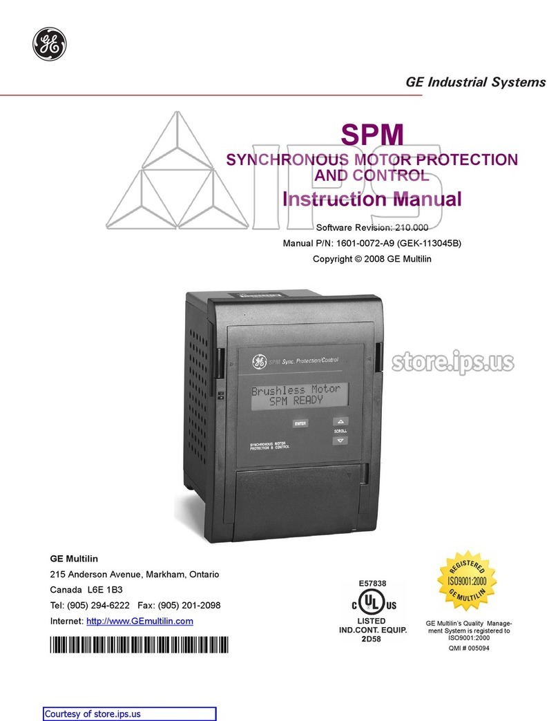
GE DTR GEK-106305A User manual

GE Multilin
215 Anderson Avenue
L6E 1B3 Markham, ON -CANADA
T (905) 294 6222 F (905) 294 8512
Internet: www.GEMultilin.com
Copyright © 2005 GE Multilin
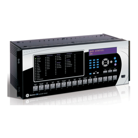
DTR
Digital Tap Changer Controller
Instruction Manual
GEK-106305A
GE Multilin
Avda. Pinoa, 10
48170 Zamudio SPAIN
T +34 94 485 88 00 F +34 94 485 88 45
gGE Consumer & Industrial
Multilin

TABLE OF CONTENTS
GEK-106305A DTR Digital Tap Changer Controller 1
TABLE OF CONTENTS
1. GENERAL DESCRIPTION AND APPLICATION 5
2. OPERATION PRINCIPLES 8
2.1 CONTROL FUNCTIONS 8
2.1.1 REGULATION ALGORITHMS.......................................................................................................................8
2.1.2 OPERATING CURVE...................................................................................................................................11
2.1.3 REGULATION AUTOMATISM.....................................................................................................................12
2.1.4 EXCESSIVE OPERATIONS BLOCK...........................................................................................................15
2.1.5 SUCCESSIVE OPERATIONS IN A CERTAIN TIME FRAME BLOCK........................................................15
2.1.6 OVERVOLTAGE, UNDERVOLTAGE AND OVERCURRENT BLOCKS.....................................................15
2.1.7 QUICK LOWERING FUNCTION..................................................................................................................15
2.2 MONITORING AND REGISTER FUNCTIONS 16
2.2.1 MEASUREMENTS.......................................................................................................................................16
2.2.2 COUNTERS .................................................................................................................................................17
2.2.3 INTERNAL STATUS.....................................................................................................................................18
2.2.4 SELF-CHECKING FUNCTIONS..................................................................................................................28
2.3 ANALYSIS FUNCTIONS 29
2.3.1 EVENT REGISTER......................................................................................................................................29
2.4 CONTROL FUNCTIONS 29
2.4.1 ALARMS TREATMENT................................................................................................................................29
2.4.2 SIGNALING..................................................................................................................................................31
2.4.3 COMMANDS ................................................................................................................................................31
2.4.4 TIME SYNCHRONIZATION.........................................................................................................................31
2.4.5 CONFIGURABLE INPUTS AND OUTPUTS................................................................................................32
2.4.6 SETTING TABLES.......................................................................................................................................34
2.5 USER INTERFACE AND COMMUNICATIONS 35
2.5.1 LOCAL USER INTERFACE .........................................................................................................................35
2.5.2 REMOTE COMMUNICATIONS. SOFTWARE.............................................................................................38
3. SETTINGS 42
3.1 SETTINGS 42
3.2 COMMENTS ABOUT THE SETTINGS 45
3.2.1 GENERAL SETTINGS .................................................................................................................................45
3.2.2 X1.REGULATION SETTINGS......................................................................................................................47
3.2.3 X2. BLOCK SETTINGS...............................................................................................................................48
3.2.4 X3. TIMERS..................................................................................................................................................48
3.2.5 X4. VOLTAGE SETPOINT...........................................................................................................................49
4. PROGRAMMING THE UNIT 50
4.1 INPUT CONFIGURATION 50
4.2 OUTPUT CONFIGURATION 53
4.3 GRAPHIC DISPLAY CONFIGURATION 53
4.4 MAIN SCREEN 54
4.5 ALARMS SCREEN 56
4.6 MEASURES SCREEN 58
4.7 INPUTS/OUTPUTS SCREEN 58
5. TECHNICAL CHARACTERISTICS 60
5.1 MODEL LIST 60
5.2 TECHNICAL CHARACTERISTICS 61
TABLE OF CONTENTS
2 DTR Digital Tap Changer Controller GE—106305A
6. HARDWARE DESCRIPTION 65
6.1 MECHANICAL CONSTRUCTION 66
6.1.1 BOX CONSTRUCTION................................................................................................................................66
6.1.2 ELECTRICAL CONNECTIONS...................................................................................................................66
6.1.3 INTERNAL CONSTRUCTION.....................................................................................................................67
6.1.4 IDENTIFICATION.........................................................................................................................................68
6.1.5 MAGNETIC MODULE..................................................................................................................................68
6.1.6 PROTECTION CPU PROCESSING BOARD..............................................................................................69
6.1.7 CPU COMMUNICATIONS BOARD.............................................................................................................69
6.1.8 DIGITAL INPUTS BOARD...........................................................................................................................69
6.1.9 DIGITAL OUTPUTS BOARD.......................................................................................................................70
6.1.10 POWER SUPPLY ........................................................................................................................................70
6.2 RECEPTION, HANDLING & STORAGE 71
6.3 INSTALLATION 71
7. ACCEPTANCE TESTS 73
7.1 VISUAL INSPECTION 73
7.2 INSULATION TEST 73
7.3 POWER SUPPLY 73
7.4 METERING 74
7.5 VERIFICATION OF INPUTS 74
7.6 COMMUNICATIONS 75
7.7 DISPLAY, KEYPAD AND LEDS. 75
7.8 VERIFICATION OF OUTPUTS, AND DTR OPERATION 76
7.8.1 VERIFICATION OF ALARM CONTACTS; LOCAL AND REMOTE: ...........................................................76
7.8.2 VERIFICATION OF RTU OUTPUTS:..........................................................................................................77
7.8.3 VERIFICATION OF THE TAP-UP/TAP-DOWN COMMANDS OPERATION:.............................................77
7.8.4 VERIFICATION OF UNDERVOLTAGE, OVERVOLTAGE, AND OVERCURRENT CONTACTS..............78
7.9 DYNAMIC VERIFICATION OF THE REGULATOR OPERATION 78
7.9.1 VERIFICATION OF THE “NUMBER OF OPERATIONS”............................................................................79
7.9.2 VERIFICATION OF THE NUMBER OF “SUCCESSIVE OPERATIONS” ...................................................80
8. INSTALLATION AND MAINTENANCE 82
8.1 INSTALLATION 82
8.2 CONNECTION TO GROUND AND SUPPRESSION OF DISTURBANCES 82
8.3 MAINTENANCE 82
9. KEYPAD AND DISPLAY 85
9.1 MENU TREE 86
9.2 SETTINGS GROUP 88
9.3 INFORMATION GROUP 92
9.4 OPERATIONS GROUP 94
9.5 SINGLE-KEY OPERATION. 95
9.6 CONFIGURATION MENU 96

TABLE OF CONTENTS
GEK-106305A DTR Digital Tap Changer Controller 3
LIST OF TABLES
Table I : Internal communications statuses
Table II : Internal protection statuses
Table III : Settings common to all tables
Table IV : Independent settings for each table
LIST OF FIGURES
Fig. 1 : Wiring diagram for DTR units with taps coded in BCD
Fig. 2 : Wiring diagram for DTR units with taps per contact
Fig. 3 : Panel mounting diagram
Fig. 4 : RS-232 connection
Fig. 5 : Dimensions diagram
Fig. 6 : Front view
Fig. 7 : Rear view

TABLE OF CONTENTS
4 DTR Digital Tap Changer Controller GE—106305A

1. GENERAL DESCRIPTION AND APPLICATION
GEK-106305A DTR Digital Tap Changer Controller 5
1. GENERAL DESCRIPTION AND APPLICATION
New technologies have allowed in the last years a significant development in the integration of functions performed
by the different components of a power system. The reason for this integration is the bigger need for reducing and
optimizing the investments in equipment and installations, as well as the management and use of energy, due to the
significant savings involved.
This integration of functions includes not only the switchgear control devices for high and low voltage, protection for
the different elements, signaling and alarms in a substation, but also the monitoring of all elements, the analysis of
the available information (events, alarms, oscillography, load/demand profiles, etc.), and certain innovative functions
such as the substation maintenance, adaptive protections, etc.
DTR units are microprocessor based relays used for the voltage control in the power system.
DTR is used in MV substations for controlling the voltage, operating on the OLTC of power transformers.
The functions integrated in these units are:
A) CONTROL:
• Transformer OLTC control
• Overvoltage unit for monitoring the OLTC control
• Undervoltage unit for monitoring the OLTC control
• Overcurrent unit for monitoring the OLTC control
• Blocking functions for excessive number of operations (totals) and for excessive number of successive operations
in a determined period of time.
• Fast backward function, if the difference to the setpoint is excessive.
B) MONITORING AND REGISTER
• Metering and display of the phase current
• Metering and display of voltage
• Metering and display of frequency
• Display of the tap value. The device accepts the tap status coded in BCD or in contact per tap (please refer to
model list)
• Metering and display of active power
• Metering and display of reactive power
• Metering and display of the power factor
• Metering and display of the voltage difference with respect to the setpoint.
• Display of the operation time
• Programmable graphic display showing the main statuses and measures
• Self check of the unit
• Counter for number of tap-ups, tap-downs and operations

1. GENERAL DESCRIPTION AND APPLICATION
6 DTR Digital Tap Changer Controller GE—106305A
C) ANALYSIS
• Event record
• Alarm record
D) INTERFACES AND COMMUNICATIONS
DTR units incorporate two communications ports. The front port is RS232, while the rear port is selectable between
RS232, RS485, plastic or glass fiber optic.
The associated software for DTR units is as follows :
• GE-LOCAL communications software, which allows the user to view and modify protection settings, alarms,
internal status, etc.
• GE-INTRO configuration software, which allows to program inputs, outputs, alarms and LEDs.
These software packages are part of the GE-NESIS network substation integration system.

2. OPERATION PRINCIPLES
GEK-106305A DTR Digital Tap Changer Controller 7
2. OPERATION PRINCIPLES
2.1 CONTROL FUNCTIONS
The transformer tap changer controller controls manually or automatically the OLTC (transformer on load tap
changer), originating tap-up and tap-down commands, in order to keep the power supply voltage practically constant,
independently from the load.
2.1.1 REGULATION ALGORITHMS
In order to achieve this voltage regulation, the DTR uses two algorithms:
1. Comparing the measured voltage with the voltage setpoint.
2. Compensating the voltage dropouts generated by the load current by means of the calculation of the apparent
current. This calculation consists of subtracting from the measured voltage, a voltage proportional to the load
current, before the measured voltage is compared with the voltage setpoint.
The main characteristics of both algorithms are:
• The variation of the measured voltage in relation to the voltage setpoint is provided with an Insensibility Degree
(ID). This ID is defined as the maximum admissible variation of the voltage before the DTR originates a
command to change the tap in the OLTC. This operation avoids the excessive wear of the OLTC contacts, with a
practically constant voltage at the same time.
• If the difference between the measured voltage and the setpoint is greater than the Insensitivity Degree will be
corrected with a certain delay Operating Time (OT), so that:
• If the difference lasts only for a short time (less than the Operation Time), the DTR system will not order
a tap change.
• The voltage deviations will be regulated proportionally to the difference between the real value and the
setpoint value. The greater the deviation is, the sooner the DTR will operate.
The way of operation of both algorithms is the following:
1. If |DV| > ID
Absolute value of the difference between the setpoint and the real voltage is greater than Insensitivity Degree
Then
An operation on the OLTC must be performed.
Otherwise
No operation will be produced on the OLTC
2. If
DV: Deviation between the real voltage and the setpoint is lower than zero
Then
There will be a tap-down operation
Otherwise
There will be a tap-up operation

2. OPERATION PRINCIPLES
8 DTR Digital Tap Changer Controller GE—106305A
The Operation Time to initiate a tap change will be calculated in the following way:
Tb = 10 * ID / |DV| tb==Base Time
OT = FT * tb
The user can set the Time Factor (FT) and DV is the deviation between the real voltage and the setpoint
calculated in the following way (depending on the selected algorithm)
Algorithm 1: Voltage regulation:
DV = V0- Vm
V0: setpoint, Vm: Measured voltage
Algorithm 2: Compensating by means of the calculation of apparent current:
DV = (V0+ Vcom) - Vm
V0=setpoint, Vm= Measured voltage
Vcom = Kcom * Im/ In
Kcom==Calculation of current (Adjustable)
Im=Measured current, In=Nominal current
Only when Vcom < Vcomax
Otherwise
Vcom = Vcomax
Vcomax==Maximum voltage increase (Adjustable).

2. OPERATION PRINCIPLES
GEK-106305A DTR Digital Tap Changer Controller 9
2.1.2 OPERATING CURVE
The standard operation times (FT=1) for different values of Insensitivity Degree are shown in the following figure:
0123 4 5 6 7 8 9 10
0
1
2
3
4
5
6
7
8
9
10 0.5%1% 2% 3% 4% 5%
GI[%] == Insensitivity Degree in %
|DU[%]| == Voltage Deviation in %
tb[sg] == Base Tiem in seconds

2. OPERATION PRINCIPLES
10 DTR Digital Tap Changer Controller GE—106305A
2.1.3 REGULATION AUTOMATISM
The following status diagram shows the behaviour of the voltage regulation automatism:
A
utomatic
Timing
Lowering
Stopped
Waiting
Lower
Manual
Raising
Waiting
Raise
Success
Raisi Failed
Raising Failed
Lowering Successful
Lowering
Raising tap command
TimeOut & DV>0
TimeOut
TimeOut
Stop command
Automatic command
Automatic command
Manual command
Stop commad
Lowering Tap command
Manual command
GI/DV>1
+
Interlock
+
Sucessive Op.
+
27+59+50
Reg. Alarm + Excessive OP. + Irregular Tap Change
Reg. Alarm + Excessive Op. + Irregular Tap Changer
TimeOut & DV<0
Tap(n) - Tap(n-1) = 1 Tap(n) - Tap(n-1) <> 1 Tap(n) - Tap(n-1) <> -1
Timeout+
TimeOut +
A
utomatic
Manual Automatic*Automatic*
Manual* Manual*
GI/DV<1
Stop command
Tap(n) - Tap(n-1) = -1
TimeOut & DV>0 & Min Tap +
TimeOut & DV<0 & Max Tap

2. OPERATION PRINCIPLES
GEK-106305A DTR Digital Tap Changer Controller 11
The steady statuses of the automatism are the following:
1. Stopped:
DTR reaches this state by means of a Stop command and it can only leave this state by means of a Manual
command or an Automatic command.
2. Automatic:
DTR reaches this state by means of an Automatic command.
In this status, DTR system is always checking if the necessary conditions exist, to initiate a OLTC operation. When
these conditions exist, a timer is started and the DTR reaches the Timing Operation Status.
3. Manual:
The DTR system reaches this status by means of a Manual command or when it is in Automatic mode and there is
an anomalous situation such as Irregular Tap Change, Regulator Alarm, Failed Tap-up/tap-down, etc. In this state
the DTR system is waiting for Tap-up, Tap-down, Automatic or Stop commands.
4. Timing Operation:
In this status, the DTR system is checking the operation conditions and counting the Operating Time. If the operation
conditions disappear, the DTR returns to Automatic state, and if the Operation Time is exceeded, the DTR system
changes to Tap-up/ Tap-down status.
5. Tap-Up:
When the DTR system is in this state, it checks whether the OLTC is in the maximum tap; if so, then the DTR system
stops the operation. Otherwise, the DTR stays in this state during the time set for Operation Pulse before changing to
Waiting for Tap-up state.
6. Tap-Down:
When the DTR system is in this state, it checks whether the OLTC is in the minimum tap; if so, then the DTR system
stops the operation. Otherwise, the DTR stays in this state during the time set for Operation Pulse before changing to
Waiting for Tap-Down state.
7. Waiting for Tap-up:
In this state, the DTR system waits for the change in the OLTC. If the Success Time finishes its count and the tap
change has been successful (OLTC has raised the tap) then the DTR changes to Successful Tap-up state, if not,
the DTR changes to Failed Tap-up.
8. Waiting for Tap-down:
In this state, the DTR system waits for the change in the OLTC. If the Success Time finishes its count and the tap
change has been successful (OLTC has lowered the tap) then the DTR changes its status to Successful Tap-down;
if not, the DTR changes to Failed Tap-Down state.
9. Successful Tap-Up:
This state shows that the tap increase operation has been successful. The DTR system returns to the initial state,
previous to the tap increase, either Manual or Automatic.

2. OPERATION PRINCIPLES
12 DTR Digital Tap Changer Controller GE—106305A
Failed Tap-UP:
This state shows that the tap increase operation has failed. The DTR system changes to the Manual state,
independently of the state previous to the Tap-up attempt.
11. Successful Tap-Down:
This state shows that the tap decrease operation has been successful. The DTR system returns to the initial state,
previous to the tap decrease, either Manual or Automatic.
12. Failed Tap-Down:
This state shows that the tap decrease operation has failed. The DTR system changes to the Manual state,
independently of the state previous to the Tap-down attempt.
2.1.4 EXCESSIVE OPERATIONS BLOCK.
This function allows the user to limit the number of raising/lowering tap operations over the OLTC. The user can set
this function for maintenance purposes.
When the DTR is in automatic mode, and the maximum number of allowed operations is exceeded, it will change to
Manual mode. This function can be disabled by setting the Maximum number of operations to zero.
2.1.5 SUCCESSIVE OPERATIONS IN A CERTAIN TIME FRAME BLOCK
This function allows the user to limit the number of raising / lowering tap operations in a specified time interval.
When the regulator is in Automatic Mode and there are continuous operations at a higher speed than the one
specified by Number of Successive Operations and Time window settings, the DTR will change to Manual mode.
Once this function is enabled, it will disable itself after a certain time without operations over the OLTC.
This function can be disabled by setting the Number of Successive Operations to zero.
2.1.6 OVERVOLTAGE, UNDERVOLTAGE AND OVERCURRENT BLOCKS.
When the DTR is in automatic mode, before performing any operation over the OLTC, it checks that the voltage
levels are within the limits specified by Overvoltage and Undervoltage settings. It also checks that the measured
current is lower than Overcurrent setting. In order to enable control over different operations when in MANUAL
mode independently from the protection element blocks, the relay incorporates three settings: BLOQ. M. OVER_V,
BLOQ. M. UNDER_V y BLOQ. M. OVER_I, which allow to consider or not the block condition.
2.1.7 QUICK LOWERING FUNCTION
If the measured voltage exceeds the value set for Quick Lowering, Then the Operating Time becomes 0 s, and
therefore the lowering tap operation is instantaneous.

2. OPERATION PRINCIPLES
GEK-106305A DTR Digital Tap Changer Controller 13
2.2 MONITORING AND REGISTER FUNCTIONS
2.2.1 MEASUREMENTS
The DTR system shows the following measurements:
Tap:
Current OLTC tap number.
Current (Amp):
Current module on the primary side of the transformer.
Primary voltage (KV):
Phase to phase voltage module on the primary side of the transformer.
Secondary voltage (V):
Phase to phase voltage module on the secondary side of the transformer.
Frequency (Hz):
Voltage Frequency
Active Power (MW):
Three phase active power on the primary side of the transformer.
Reactive Power (MVar):
Three phase reactive power on the primary side of the transformer.
cos phi:
Power factor.
Setpoint (V):
Voltage setpoint (phase to phase).
Rated voltage (V):
Rated voltage (setting)
V difference: (V)
Difference between the real voltage and the setpoint.
Operation Time (s):
Operation time to initiate a tap change.
These measurements can be accessed by means of the two displays on the front of the relay (HMI), or via
communications using the GE_LOCAL software.

2. OPERATION PRINCIPLES
14 DTR Digital Tap Changer Controller GE—106305A
2.2.2 COUNTERS
The DTR system incorporates the following counters, which can be started and checked independently:
Number of RAISING OPERATIONS performed on the OLTC.
Number of LOWERING OPERATIONS performed on the OLTC.
Number of total OPERATIONS performed on the OLTC.
These counters can be accessed by means of the HMI (display on the front of the relay) or by the GE_LOCAL
communications software:

2. OPERATION PRINCIPLES
GEK-106305A DTR Digital Tap Changer Controller 15
2.2.3 INTERNAL STATUS
On the Internal Status, the system shows all the internal digital flags (inputs, pickups, alarms, etc.). The available
signals in the internal status are grouped in 10 groups of 16 signals each. The last group is the ANDs group; these 16
AND gates may be used by the user to design logic circuits using GE_INTRO software. The inputs to an AND gate
may be internal flags or the output of other AND gate.
1st group
Program initiate Parallel EEPROM alarm
Settings change Serial EEPROM alarm
Write counters
New events Default general settings
Date/Time lost Default table 1 settings
Out of service Default table 2 settings
Default table 3 settings
2nd group
External trigger
Active table 1
Active table 2
Active table 3 |DV|>GI,
Communications trigger Quick Lowering
Stopped Overvoltage
Automatic (operation mode) Undervoltage
Remote Overcurrent
3rd group
4th group
REM TRIP command LOCAL command
REMOTE command
STOP command
AUTOMATIC command
MANUAL command

2. OPERATION PRINCIPLES
16 DTR Digital Tap Changer Controller GE—106305A
TAP-UP command
TAP-DOWN command
5th group
E01, E08,
E02, E09,
E03, E10,
E04, E11,
E05, E12,
E06, E13,
E07, E14,
, ,
6th group
E15, E22,
E16, E23,
E17, E24,
E18, E25,
E19, E26,
E20, E27,
E21, E28,
, ,
7th group
E29, E36,
E30, E37,
E31, E38,
E32, E39,
E33, E40,
E34, E41,
E35, E42,
, ,
8th group
STOPPED TAP-DOWN PULSE
AUTOMATIC (automat status) TAP-DOWN TIME
MANUAL TAP-DOWN = SUCCESS
TIMING TAP-DOWN = FAIL
TAP-UP PULSE
TAP-UP TIME REM TRIP pulse
TAP-UP = SUCCESS HOLD TRIP REM
TAP-UP = FAIL
9th group
E-LOCAL REG INTERBLOCK-1
E-REMOTE REG INTERBLOCK-2

2. OPERATION PRINCIPLES
GEK-106305A DTR Digital Tap Changer Controller 17
E-TRIP REM SUCCESSIVE OP.
E-STOP REGULATOR ALARM
E-AUTOMATIC MAXIMUM TAP
E-MANUAL MINIMUM TAP
E-TAP-UP IRREGULAR CHANGE
E-TAP-DOWN EXCESSIVE OPERATIONS
10th group
AND1, AND9,
AND2, AND10,
AND3, AND11,
AND4, AND12,
AND5, AND13,
AND6, AND14,
AND7, AND15,
AND8, AND16,
COMMENTS ON INTERNAL STATUS
PROGRAM INITIATE
This signal becomes active when the DTR system has successfully passed all the internal Self-tests and
initializations. This signal can be useful to be assigned to an output with an alarm meaning, either as it is, or inverted.
SETTINGS CHANGE
When a settings change is performed, this signal becomes active and it gets deactivated when the system
generates the corresponding event.
WRITE COUNTERS
When a change on any counter is done, this signal becomes active, and it gets deactivated when the system
generates the corresponding event.
NEW EVENTS
This signal becomes active when new events are generated, and gets deactivated when these new events are
retrieved from a computer.
DATE/TIME LOST
This signal is active when the system is powered-up (PROGRAM INITIATE) without a previous time
synchronization.
OUT OF SERVICE
This signal is active when the DTR system setting 1.1.- RELAY STATUS is set to Out of Service.

2. OPERATION PRINCIPLES
18 DTR Digital Tap Changer Controller GE—106305A
PARALLEL EEPROM ALARM
This signal becomes active when the system detects an error on the non-volatile RAM (Parallel EEPROM) where
event list and counters are stored.
SERIAL EEPROM ALARM
This signal becomes active when the system detects an error on the non-volatile RAM (Serial EEPROM), where
a duplicate of the unit settings are stored (duplicated).
DEFAULT GENERAL SETTINGS
If the General Settings have never been changed, the system has the factory default General Settings. This signal
shows this situation.
TABLE 1 DEFAULT SETTINGS
If the settings on Table 1 have never been changed, the system has the factory default Table 1 settings. This
signal shows this situation.
TABLE 2 DEFAULT SETTINGS
If the settings on Table 2 have never been changed, the system has the factory default Table 2 settings. This
signal shows this situation.
TABLE 3 DEFAULT SETTINGS
If the settings on Table 3 have never been changed, the system has the factory default Table 3 settings. This
signal shows this situation.
EXTERNAL TRIGGER
This signal turns ON and OFF as the External Trigger Digital Input is energized and de-energized.
TABLE 1 ACTIVE
TABLE 2 ACTIVE
TABLE 3 ACTIVE
These three signals report which table is active each time. If the digital inputs intended to change tables are de-
energized, then these signals would reflect the value set on setting ACTIVE TABLE.
COMMUNICATIONS TRIGGER
This signal becomes active when a trigger command is issued, either from the local HMI (keyboard and display on
the front of the relay) or from the GE_LOCAL communications software.
STOPPED
This signal becomes active when the regulation automatism is stopped.

2. OPERATION PRINCIPLES
GEK-106305A DTR Digital Tap Changer Controller 19
AUTOMATIC
This signal shows the operation mode of the regulation automatism, and it can be either Automatic or Manual.
REMOTE
This signal shows the mode of the OLTC, either Remote or Local.
|DV| > ID
This signal becomes active when the absolute value of the difference between the measured voltage (real voltage)
and the setpoint is greater than the Insensitivity Degree, and therefore the DTR system has to start an operation on
the OLTC.
QUICK LOWERING
This signal becomes active when the measured voltage is greater than the Quick Lowering setting and, therefore,
the regulation automatism (in automatic mode) will perform a tap decrease without waiting the operating time.
OVERVOLTAGE
This signal becomes active when the measured voltage is greater than the OVERVOLTAGE setting and, therefore,
the regulation automatism (in automatic mode) will not operate.
UNDERVOLTAGE
This signal becomes active when the measured voltage is lower than the UNDERVOLTAGE setting and, therefore,
the regulation automatism (in automatic mode) will not operate.
OVERCURRENT
This signal becomes active when the measured current is greater than the OVERCURRENT setting and, therefore,
the regulation automatism (in automatic mode) will not operate.
REM TRIP COMMAND
This signal indicates that the unit has Received a Remote Trip Command via communications
STOP COMMAND
This signal becomes active when the DTR receives by communications a command to stop the regulation
automatism.
AUTOMATIC COMMAND
This signal becomes active when the DTR receives by communications a command to change the regulation
automatism to AUTOMATIC mode.
MANUAL COMMAND
This signal becomes active when the DTR receives by communications a command to change the regulation
automatism to manual mode.
Table of contents
Other GE Controllers manuals