Westken information manuals and technical assistance
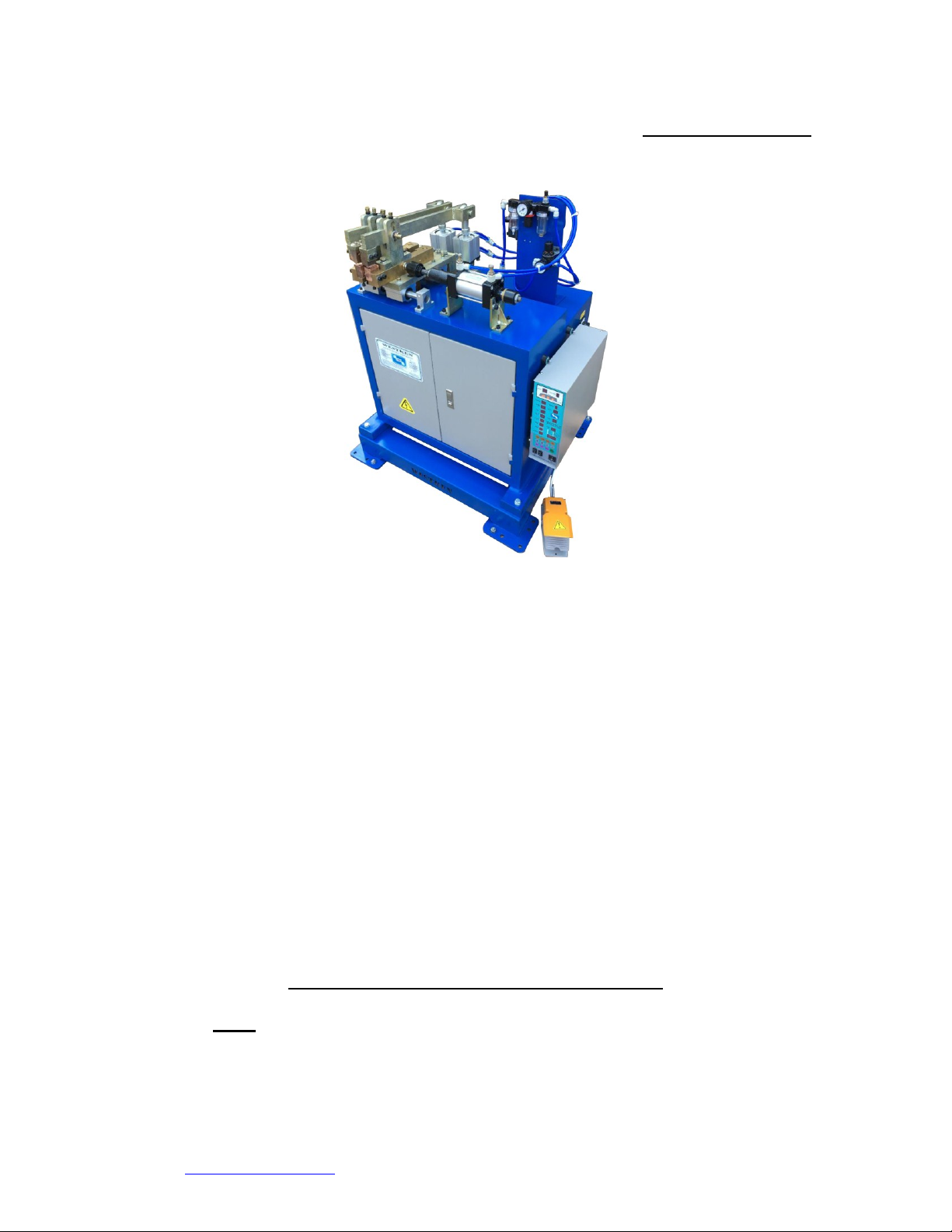
General Manual for UN35 Butt Welder
Westken, 190 van Eden crescent, Rosslyn, Pretoria, South Africa.
www.westken.co.za (Tel; 0027 12 541 6064/6065 fax; 0027 12 541 8086)
full range of welding machines from the 25kva foot pedals up to 450kva Projection
welder.
All air operated butt welding machines use an air cylinder to close the welding electrodes
together and to upset the welding area, whether it’s the “UN35” or “Level-6 100kva butt
welder the method is the same.
The welders utilize a technique called “Resistance Welding”. Resistance welding is a
process where metal is held between two electrodes, lots of amps (thousands) but low
volts (3v –10v) are pushed through the metal causing the metal to get hot and melt in
between the electrodes. Then after the metal melts the supply of the amps is stopped
allowing the metal to cool and bond. Once the metal is cool the electrodes let go of the
metal and you have a weld.
The operator pushes the electric foot switch or, where fitted the two hands start switch,
this switch triggers the welding timer to begin its process.
The first operation the timer undertakes is to send a signal to the air solenoid valve (air
flow switch) to allow air to travel to the air cylinder. This pushes the piston in the
cylinder down and closes the welding tips.
Once the tips are together the timer then switches the Thyristor switch (also call the SCR,
AC switch, Semipack) which allows electricity to flow into the transformer. The
electricity coming into the transformer is normally 380vs at about 80amps. The
transformer changes this (transforms) supply to about 4.5volts at 9000amps output.
Because the clamping electrodes are closed this AC volts/amps will pass through them
and into the steel being welded causing the steel to heat up in the weld area. As the
heated area starts to melt the upset air cylinder pushes the two parts together. This
upsetting pressure ensures that when the weld takes place the wet metals combine to
make a secure weld; this is called follow-up pressure or forging pressure.
An introduction to the machines
We are now looking at the machine with its electronic device with its readout screens,
lights and buttons; it’s a bit confusing, hey! Read this and it will hopefully make things a
bit more clear.
As stated above the air Butt welding machines are all similar but I will highlight machine
specific parts and describe them in a bit more depth.
I will discuss timer setting which can be found further on in this manual. It is important
that you have read the other sections concerning spotwelding and resistance welding, so
now, once again, let’s try and explain in a way that is understandable without using too
many big words, technical terms or baffling phrases.