TABLE OF CONTENTS PAGE
Introduction
...................................................................................................
1
Serial Plate Locations ........................................................................................
..
1
Safety
...
............................................................................................
.
.........
3
Safety Decals
...............................................................................................
4,5
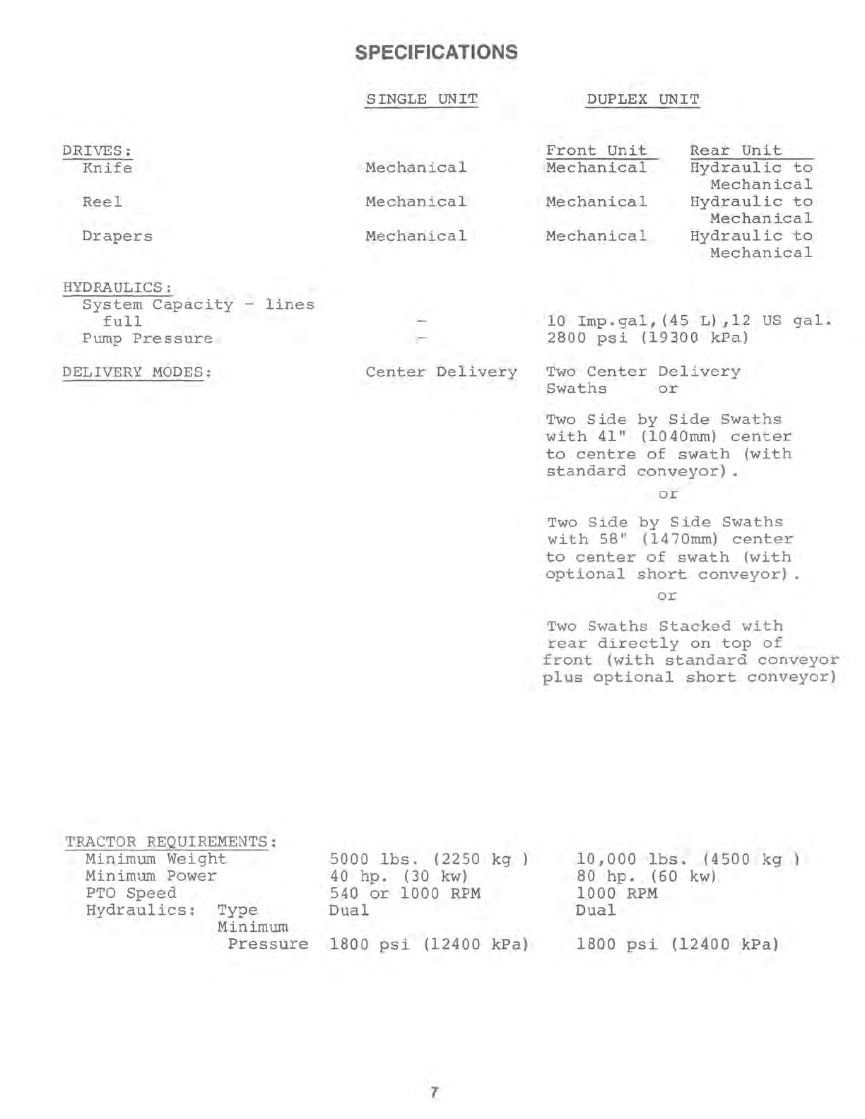
Specifications
...............................................................................................
6,7
Operation
At
First
Use-
Electrical Hook-Up
.............................................................................
8,9
-
PTO
Adjustment
.............................................
....
...............................
10
-Optional Hitch Plate
.........................
.......
............................................
11
-Duplex Initial Field Adjustments
..............................................................
11,12
-Hydraulic Oil Filter
..............................................................................
12
-
Wheel
Bolts
...........................................
............
...................
..........
12
Switch
Box
...................................................................................................
13
Pre-Season Check
............................................................................................
14
End of Season Check
..........................................................................................
14
Transporting-General
........................................................................................
15
-Single Unit -Field to Transport
.................................
..........
........................
16
-Single Unit -Transport to Field
................................................................
17,18
-Duplex Unit -Field to Transport
...........................
...
.................................
19-22
-Duplex Unit -Transport to Field
............
..
.................................................
23-26
Changing Modes of Delivery -Description of Modes
..............................................................
26
-Center to
End
...•................................................................
27
-Conveyor Extension Package (Option)
..............................................
28
To
Separate and Re-Connect Duplex Units
........................................................................
29
Duplex Operating Tips
.............................................
........
.................
............
.....
30,31
Trouble Shooting
Swath Formation: Center Delivery
..............................................................................
32
Crop Loss at Cutter Bar
.......................................................................................
33
Crop Loss at Drapers
..........................................................................................
33
Transport
.....................................................................................................
34
Drives
..............................................
. . .
.....................
...
............................
35,36
Duplex Tracking
..............................................................................................
37
Duplex Cornering
..........................................................................................
38,39
Duplex Swath Formation: End Delivery
.........................................................................
40
Duplex Hydraulic System
......................................................................................
41
Duplex Electrical System
......................................................................................
42
Duplex Transport & Conversion
................................................................................
43
Duplex Center Deck
...........................................................................................
43
Adjustment & Maintenance
Main
Drives -Idler
Alignment
...............................................................................
44
-Belt Tension
.........
...............
..........
.................................
...............
44
-Rear Unit
Main
Drive Belt Tension
..............................................................
45
-Rear Unit Clutch Drive Belt Tension
............................................................
45
Knife -Drive Belt Tension
........................................
..............
...............
.
.............
46
-Maintenance
...........................................................
......
.....
...
...............
47
Reel -Horizontal Position
...................................................................................
48
-Safety Props
.........................................................................................
48
-Clearance From Cutterbar
................................................
.........
...............
...
.
49
-Centering
...........................................................................................
49
-Drive Idler Position
...................................................................................
50
-Primary Drive Belt Tension
...........................................................................
50
-Final Drive Belt Tension
......................................................
.
...............
........
51
-Speed
................................................................
........
.......................
52
Drapers -Tracking
.......................................................................................
53,54
-Tension
.............................................
..
........
...........
........................
54
-Speed
............................................................................................
55
-Drive Belt Travel
..................................................................................
55
-Delivery Opening
..................................................................................
56
Head Lift Cylinder Stop
........................................................................................
57
Header Float
..................................................................................................
57
Wheel
Alignment
..............................................................
......
.........................
58
Trail
Width
....................................................................
...........................
....
59
Telescoping Hitch Shear Bolt
..................................................................................
59
Duplex Hitch -Rear Machine Overlap
......................................................................
60,61
-Hitch Spring
..................................................................................
62
Front Wheel Steering Spring
...................................................................................
62
Front Wheel Support Dis-assembly
.............................................................................
63
Hydraulic System-Maintenance
..............................................................................
64
-Single
Unit
Schematic
.....................................................................
64
-Duplex Unit Schematic
....................................................................
65
Electrical System -Schematic
................................................................................
66
Lubrication & Periodic Maintenance-
10
Hour
.................................................................
67
-
50
Hour
.................................................................
68
-
End
of Season
........................................................
69-71
A~~~~~I~harts
.............................................................................................
72-75
Single Unit or Front Duplex Unit
............................................................................
76-95
Rear Duplex
Unit
........................................................................................
96-117