2
WM540 High Performance Microstepping Driver
_____________________________________________________________________________________________
Table of Contents
1. Introduction, Features and Applications ·································································2
2. Specifications and Operating Environment ····························································2
3. Driver Connectors P1 and P2 ·················································································3
4. Power Supply ········································································································.4
5. Driver Voltage and Current ····················································································4
6. Selecting Microstep Resolution and Driver Current ··············································5
7. Control Signal Connector (P1) Interface ································································6
8. Protection Features ·································································································8
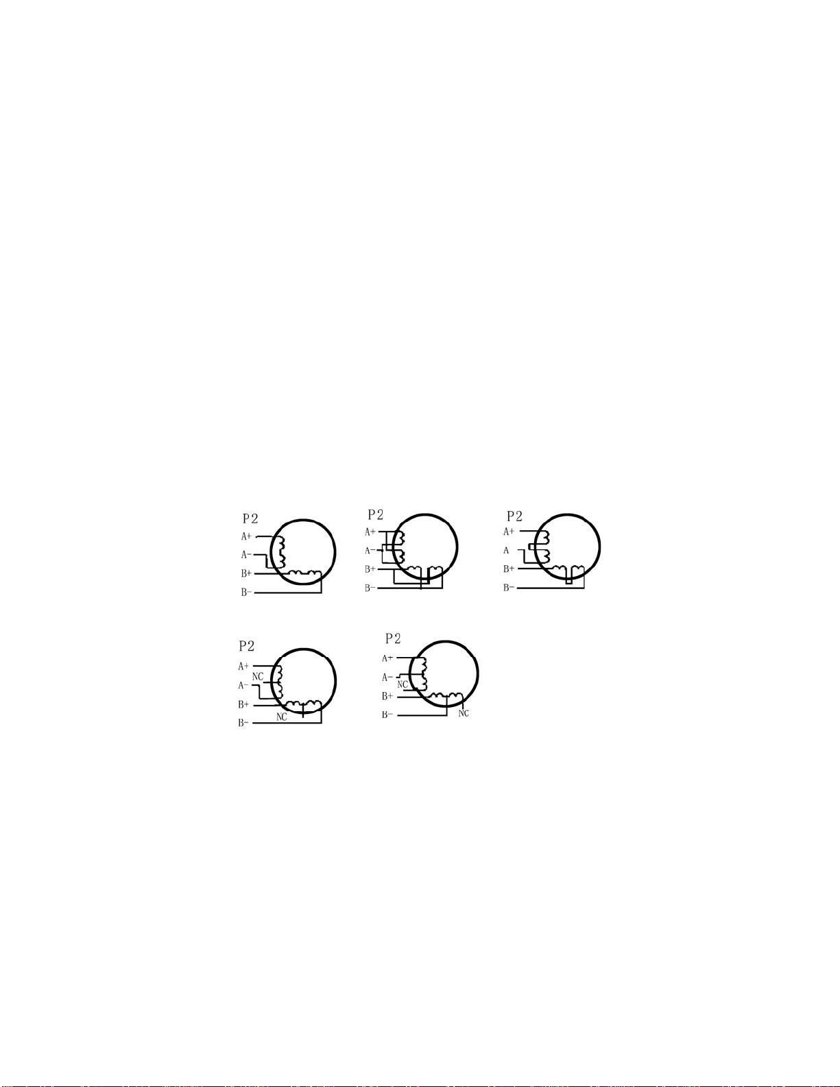
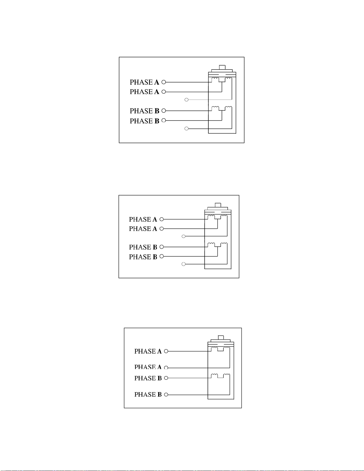
9. Driver Connection to Motors ················································································ 8
10. Connection Diagram for Driver, Motor, Controller ··············································11
11. Control signal waveform and timing ·····································································11
1. Introduction, Features and Applications
WM540 Driver is a high performance microstepping driver based on the most advanced technology in the world today.
It is suitable for driving 2-phase and 4-phase hybrid step motors (current 4.0A). By using advanced bipolar constant-
current chopping technique, it can output more speed and power from the same motor, compared with traditional
technologies such as L/R drivers. Its current control technology allows coil currents to be accurately controlled, with
much less current ripple and motor heating than other drivers on the market.
Features of this driver
•High performance, low cost
•Supply voltage up to +45VDC*, current to 4.0A for WM540 Driver
•Inaudible 20khz chopping frequency
•TTL compatible and optically isolated input signals
•Automatic idle-current reduction
•Mixed-decay current control for less motor heating
•14 selectable resolutions in decimal and binary
•Microstep resolutions up to 25,000 steps/rev
•Suitable for 4,6,8 lead motors
•Over-current, over-voltage and short-circuit protection
•Small size (118 x 76 x 34mm)
Applications of this driver
Suitable for a wide range of stepping motors such as low voltage versions of sizes 11, 14, 17, 23, and usable for various
kinds of machines, such as X-Y tables, labeling machines, laser cutters, engraving machines, and pick-place devices,
particularly useful in applications with low noise, low vibration, high speed and high precision requirements.
2. Specifications and Operating Environment
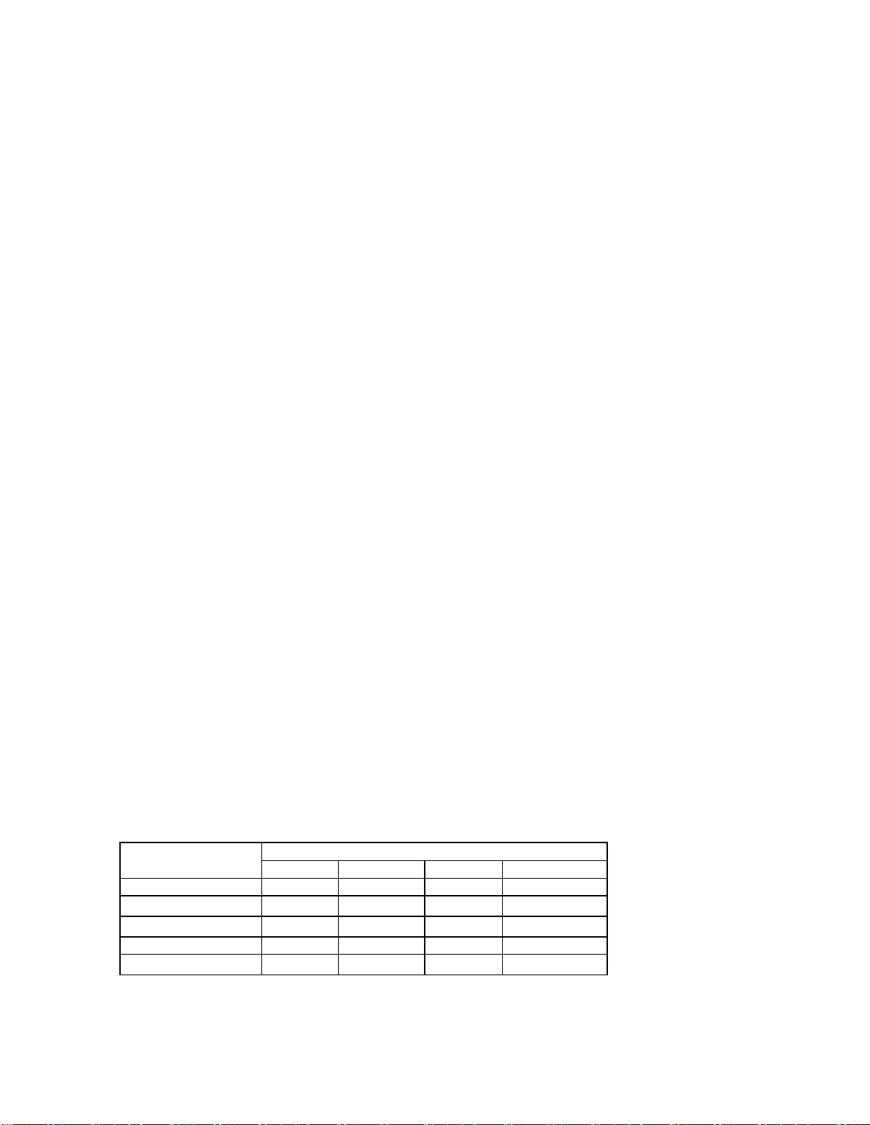
Electric Specifications (Tj = 25℃)
WM540
Parameters Min Typical Max Remark
RMS Output Current 0.5A by user 4.0A By DIP switch
Supply voltage (DC) +20V +36V +45V *
Logic signal current 10mA 12mA 18mA
Pulse input frequency 0 By user 500Khz
Isolation resistance 500MΩ
* For the European Market – the maximum input voltage must be limited to 70VDC to comply with CE regulations.