Page 2
To +12VDC
To +12VDC
To +12VDC
To Ground
WHT/VIO
LED#1
LED#2
BLACK
GREY SYNC
1A Fuse
3A Fuse
3A Fuse
SP/ST
SP/ST
MOM. SW
M6 Lighthead
(Split)
5.420" 2.710"
0.25"
0.625"
0.25"
M
O
U
N
T
I
N
G
S
U
R
F
A
C
E
#8 x 1"
Sheet Metal
Screw
M6 Assembly
Slotted Hole
Screw Grommet
(note orientation)
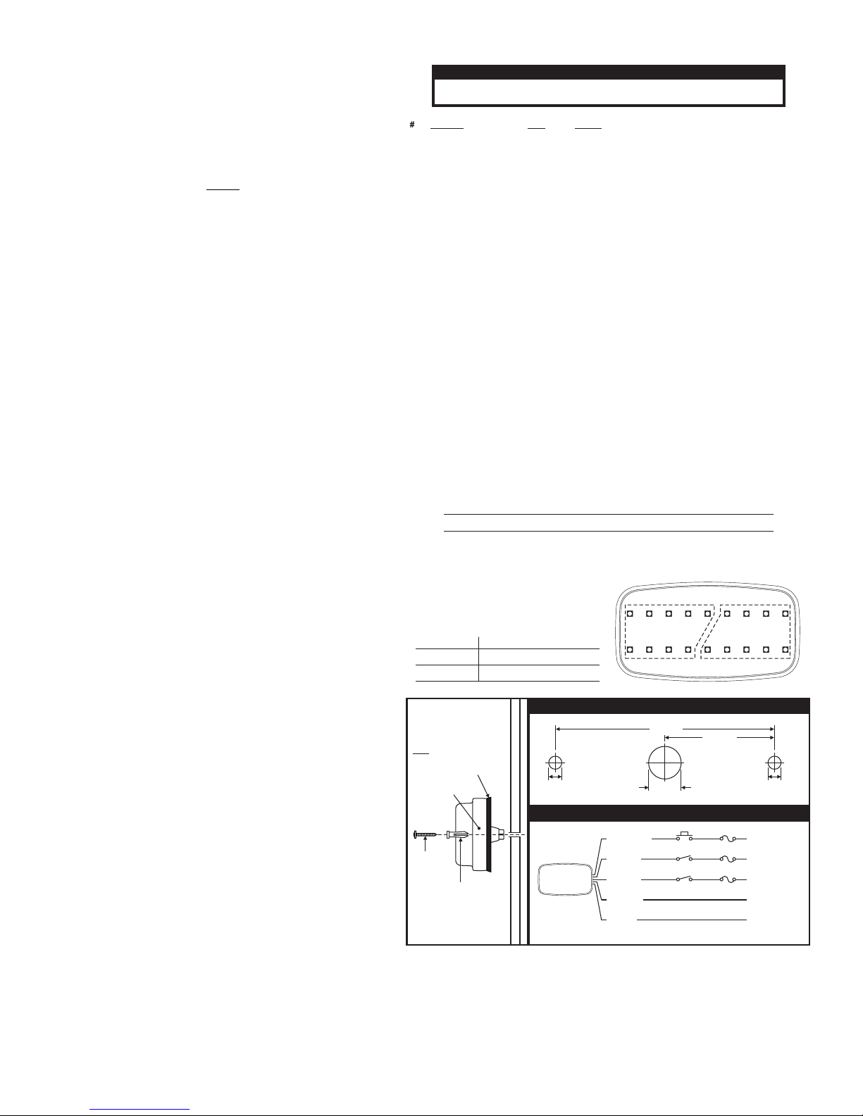
MOUNTING DIMENSIONS
WIRING DIAGRAM
Gasket Note - Use the
rubber gasket on flat,
smooth surfaces .
For diamond plate, use
the adhesive-backed
gasket (applied to the
rear of the lighthead).
only
only
ITALIC = SYNCBOLD = California Title XIII Compliant L/R=Left/Right
Sequences Operation of LED sets
Left to Right
Solid
12
All On All Off
Alternates with
Alternates with
M6 Sequencing & Phasing: The M6
lighthead has 2 sets of 9 LEDs. These
sets cycle through the sequences
shown below:
12
NOTE: Phase 1 and Phase 2 patterns are visually indistinguishable from each other
unless two or more lightheads are SYNC'd together.
Pattern
Seq.
Phase
1 SignalAlert™ CAL L/R PH.1
2
30 SingleFlash 60 Solid
SignalAlert CAL L/R PH.2
3 SignalAlert CAL Solid PH.1
4 SignalAlert CAL Solid PH.2
9 DoubleFlash 75 L/R PH.1
10 DoubleFlash 75 L/R PH.2
11 DoubleFlash 75 Solid PH.1
12 DoubleFlash 75 Solid PH.2
13 SingleFlash 75 L/R PH.1
14 SingleFlash 75 L/R PH.2
15 SingleFlash 75 Solid PH.1
16 SingleFlash 75 Solid PH.2
25 PingPong™ 75 L/R PH.1
26 PingPong 75 L/R PH.2
27 PingPong 75 Solid PH.1
28 PingPong 75 Solid PH.2
29 SingleFlash 60 L/R
31 SingleFlash 90 L/R
32 SingleFlash 90 Solid
33 SingleFlash 120 L/R
5 CometFlash®75 L/R PH.1
6 CometFlash 75 L/R PH.2
7 CometFlash 75 Solid PH.1
8 CometFlash 75 Solid PH.2
17 ComAlert™ 75 L/R PH.1
18 ComAlert 75 L/R PH.2
19 ComAlert 75 Solid PH.1
20 ComAlert 75 Solid PH.2
21 LongBurst™ 75 L/R PH.1
22 LongBurst 75 L/R PH.2
23 LongBurst 75 Solid PH.1
24 LongBurst 75 Solid PH.2
34 SingleFlash 120 Solid
61 SignalAlert w/Steady
62 SingleFlash 75 w/Steady
35 SingleFlash 300 L/R
36 SingleFlash 300 Solid
37 DoubleFlash 150 L/R
38 DoubleFlash 150 Solid
39 ComAlert™150 L/R
40 ComAlert 150 Solid
41 ActionFlash™50 L/R
42 ActionFlash 50 Solid
43 ActionFlash™150 L/R
44 ActionFlash 150 Solid
45 ModuFlash™ L/R
46 ModuFlash Solid
60 ActionScan™
47 DoubleFlash 120 L/R
48 DoubleFlash 120 Solid
49 PingPong™120 L/R
50 PingPong 120 Solid
51 TripleFlash™75 L/R
52 TripleFlash 75 Solid
53 TripleFlash 120 L/R
54 TripleFlash 120 Solid
55 Action SF60/120 L/R
56 Action SF60/120 Solid
57 Action SF120/TF75 L/R
58 Action SF120/TF75 Solid
59 CalScan™
63 SignalAlert™ Steady
64 Steady
Installation and Wiring:
Caution: Permanent mounting of this product will require drilling.
It is absolutely necessary to make sure that no other vehicle
components could be damaged by this process. Check both sides
of the mounting surface before starting. If damage is likely, select a
different location.
WARNING! All customer supplied wires that connect to the positive
terminal of the battery must be sized to supply at least 125% of the
maximum operating current and FUSED at the battery to carry that
load. DO NOT USE CIRCUIT BREAKERS WITH THIS PRODUCT!
NOTE: The color of the Positive Wire is determined by the color of
the LED. In this manual, RED is used as a reference color.
1. Using the dimensions below, mark the mounting and wire hole
locations onto the proposed mounting surface. Drill two, .250"
diameter mounting holes and a .625" (minimum) wire access hole into
the mounting surface.
2. Place the appropriate gasket into position on the rear of the M6
assembly (see Gasket Note). Insert the slotted hole screw grommet
through the mounting holes on the M6/Gasket assembly so that it is
flush with the lens.
3. Feed the M6 wires through the wire access hole in the mounting
surface. Press the M6/Gasket/Grommet assembly onto its mounting
location so that it is flat against the mounting surface.
4. With the assembly in position and using the hardware provided,
tighten the mounting screws until the lighthead assembly is drawn
firmly against the mounting surface. A torque value of 12 in-lb. (max.)
is typically required to achieve this. DO NOT OVER TIGHTEN!
5. Using appropriately sized wires (minimum 18 AWG), extend the M6
wires to their designated connections. Refer to the diagram below for
wiring and fusing information.
Operation:
Flash Mode / RED:
Apply +12V to the RED wire to activate the lighthead in “flash mode”.
With flash mode activated, you may change the flash pattern using Scan-
Lock™.
SYNC / GREY
To SYNC two lightheads, configure both lightheads to display the same
Phase 1 (Simultaneous) pattern. Turn the power off and connect the
GREY wire from each lighthead together. When the lightheads are acti-
vated their patterns will be synchronized. To configure two lightheads to
alternate their patterns, advance the pattern of either lighthead to Phase
2 (Alternating) of the current pattern.
Scan-Lock™ / WHT/VIO / Flash Pattern Selection:
This feature allows the user to select from several available flash
patterns. The lighthead must be switched on for Scan-Lock™ to work.
TO CYCLE THROUGH ALL PATTERNS: Apply positive voltage to the
WHT/VIO wire for less than 1 second and release. To cycle backward
through patterns apply positive voltage to the WHT/VIO wire for over 1
second and release.
TO SET A PATTERN AS DEFAULT: Allow the pattern to run for more
than 5 seconds. The lighthead will flicker slightly when the pattern locks
in. This flicker may be difficult to see with some patterns. The lighthead
will now display this pattern when activated.
TO RESET TO THE FACTORY DEFAULT PATTERN: Turn off power.
While applying positive voltage to the WHT/VIO wire, turn power on. This
will reset the lighthead to it’s factory default flash pattern.
IMPORTANT! It is the responsibility of the installation technician to
make sure that the installation and operation of this product will not
interfere with or compromise the operation or efficiency of any
vehicle equipment!
CAUTION! DO NOT LOOK DIRECTLY AT THESE LED’S WHILE THEY ARE ON.
MOMENTARY BLINDNESS AND/OR EYE DAMAGE COULD RESULT!
IMPORTANT WARNING!


