manuals.online logo
Brands
  1. Home
  2. •
  3. Brands
  4. •
  5. Whelen Engineering Company
  6. •
  7. Control System
  8. •
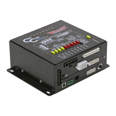
  9. Whelen Engineering Company PCCS9R User manual

Whelen Engineering Company PCCS9R User manual

Page 1
©1998 Whelen Engineering Company Inc.
Form No.13315C (121401)
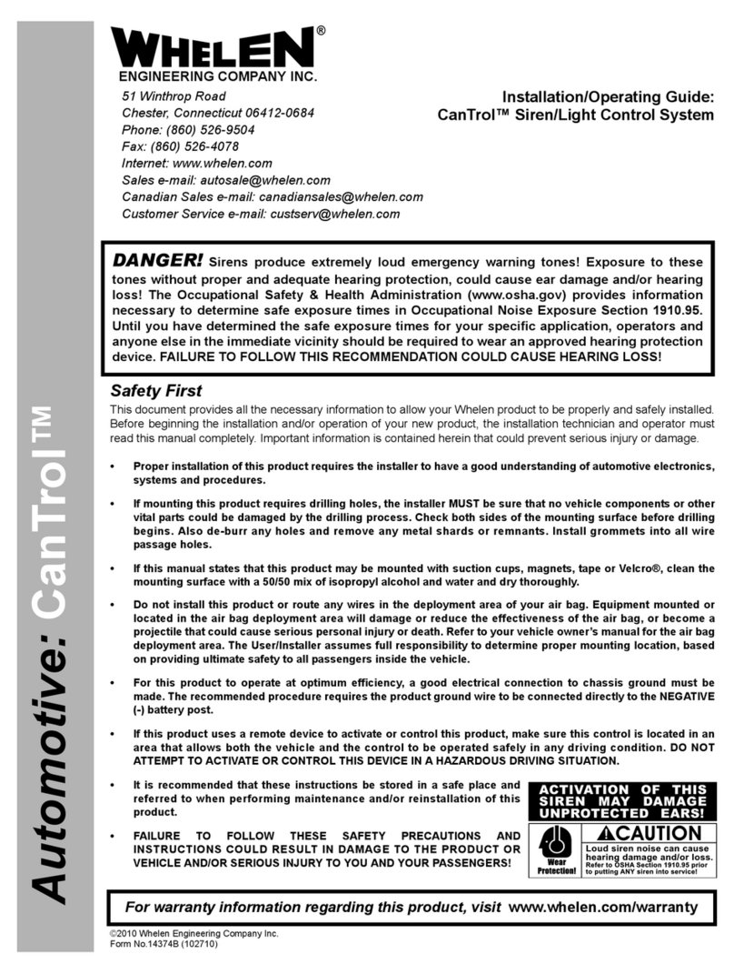
Automotive: Sirens/Switches
For warranty information regarding this product, visit www.whelen.com/warranty
DANGER! Sirens produce extremely loud emergency warning tones! Exposure to these tones without proper and adequate hearing protection, could
cause ear damage and/or hearing loss! The Occupational Safety & Health Administration (www.osha.gov) provides information necessary to determine
safe exposure times in Occupational Noise Exposure Section 1910.95. Until you have determined the safe exposure times for your specific application,
operators and anyone else in the immediate vicinity should be required to wear an approved hearing protection device. Failure to follow this
recommendation could cause hearing loss!
• Proper installation of this product requires the installer to have a good understanding of automotive electronics, systems and procedures.
• Whelen Engineering requires the use of waterproof butt splices and/or connectors if that connector could be exposed to moisture.
• Any holes, either created or utilized by this product, should be made both air- and watertight using a sealant recommended by your vehicle
manufacturer.
• Failure to use specified installation parts and/or hardware will void the product warranty.
• If mounting this product requires drilling holes, the installer MUST be sure that no vehicle components or other vital parts could be damaged
by the drilling process. Check both sides of the mounting surface before drilling begins. Also de-burr the holes and remove any metal shards
or remnants. Install grommets into all wire passage holes.
• If this manual states that this product may be mounted with suction cups, magnets, tape or Velcro®, clean the mounting surface with a 50/50
mix of isopropyl alcohol and water and dry thoroughly.
• Do not install this product or route any wires in the deployment area of your air bag. Equipment mounted or located in the air bag deployment
area will damage or reduce the effectiveness of the air bag, or become a projectile that could cause serious personal injury or death. Refer to
your vehicle owner’s manual for the air bag deployment area. The User/Installer assumes full responsibility to determine proper mounting
location, based on providing ultimate safety to all passengers inside the vehicle.
• For this product to operate at optimum efficiency, a good electrical connection to chassis ground must be made. The recommended
procedure requires the product ground wire to be connected directly to the NEGATIVE (-)
battery post (this does not include products that use cigar power cords).
• If this product uses a remote device for activation or control, make sure that this device is
located in an area that allows both the vehicle and the device to be operated safely in any
driving condition.
• It is recommended that these instructions be stored in a safe place and referred to when
performing maintenance and/or reinstallation of this product.
• FAILURE TO FOLLOW THESE SAFETY PRECAUTIONS AND INSTRUCTIONS COULD RESULT
IN DAMAGE TO THE PRODUCT OR VEHICLE AND/OR SERIOUS INJURY TO YOU AND YOUR
PASSENGERS!
CAUTION
Loud siren noise can cause
hearing damage and/or loss.
Refer to OSHA Section 1910.95 prior
to putting ANY siren into service!
Wear
Protection!
ACTIVATION OF THIS
SIREN MAY DAMAGE
UNPROTECTED EARS!
Warnings to Installers
Whelen’s emergency vehicle warning devices must be properly mounted and wired in order to be effective and safe. Read and follow all of Whelen’s written
instructions when installing or using this device. Emergency vehicles are often operated under high speed stressful conditions which must be accounted for
when installing all emergency warning devices. Controls should be placed within convenient reach of the operator so that they can operate the system without
taking their eyes off the roadway. Emergency warning devices can require high electrical voltages and/or currents. Properly protect and use caution around
live electrical connections.Grounding or shorting of electrical connections can cause high current arcing, which can cause personal injury and/or vehicle
damage, including fire. Many electronic devices used in emergency vehicles can create or be affected by electromagnetic interference. Therefore, after
installation of any electronic device it is necessary to test all electronic equipment simultaneously to insure that they operate free of interference from other
components within the vehicle. Never power emergency warning equipment from the same circuit or share the same grounding circuit with radio
communication equipment. All devices should be mounted in accordance with the manufacturer’s instructions and securely fastened to vehicle elements of
sufficient strength to withstand the forces applied to the device. Driver and/or passenger air bags (SRS) will affect the way equipment should be mounted. This
device should be mounted by permanent installation and within the zones specified by the vehicle manufacturer, if any. Any device mounted in the deployment
area of an air bag will damage or reduce the effectiveness of the air bag and may damage or dislodge the device. Installer must be sure that this device, its
mounting hardware and electrical supply wiring does not interfere with the air bag or the SRS wiring or sensors. Mounting the unit inside the vehicle by a
method other than permanent installation is not recommended as unit may become dislodged during swerving; sudden braking or collision. Failure to follow
instructions can result in personal injury. Whelen assumes no liability for any loss resulting from the use of this warning device. PROPER INSTALLATION
COMBINED WITH OPERATOR TRAINING IN THE PROPER USE OF EMERGENCY WARNING DEVICES IS ESSENTIAL TO INSURE THE SAFETY OF
EMERGENCY PERSONNEL AND THE PUBLIC.
Warnings to Users
Whelen’s emergency vehicle warning devices are intended to alert other operators and pedestrians to the presence and operation of emergency vehicles and
personnel. However, the use of this or any other Whelen emergency warning device does not guarantee that you will have the right-of-way or that other
drivers and pedestrians will properly heed an emergency warning signal. Never assume you have the right-of-way. It is your responsibility to proceed safely
before entering an intersection, driving against traffic, responding at a high rate of speed, or walking on or around traffic lanes. Emergency vehicle warning
devices should be tested on a daily basis to ensure that they operate properly. When in actual use, the operator must ensure that both visual and audible
warnings are not blocked by vehicle components (i.e.: open trunks or compartment doors), people, vehicles, or other obstructions. It is the user’s responsibility
to understand and obey all laws regarding emergency warning devices. The user should be familiar with all applicable laws and regulations prior to the use of
any emergency vehicle warning device. Whelen’s audible warning devices are designed to project sound in a forward direction away from the vehicle
occupants. However, because sustained periodic exposure to loud sounds can cause hearing loss, all audible warning devices should be installed and
operated in accordance with the standards established by the National Fire Protection Association.
Safety First
This document provides all the necessary information to allow your Whelen product to be properly and safely installed. Before beginning the installation and/or
operation of your new product, the installation technician and operator must read this manual completely. Important information is contained herein that could
prevent serious injury or damage.
WARNING: This product can expose you to chemicals including Lead which is known to the State of California to cause cancer and birth defects or
other reproductive harm. For more information go to www.P65Warnings.ca.gov.
Installation Guide:
PCCS9R Power Control Center
51 Winthrop Road
Chester, Connecticut 06412-0684
Phone: (860) 526-9504
Internet: www.whelen.com
Sales e-mail: autosale@whelen.com
Customer Service e-mail: [email protected]
®
ENGINEERING COMPANY INC.
Page 2
WARNING!
DISCONNECTING THE VEHICLE BRAKE LAMP
CIRCUIT USING ANY SIRENS WITH RELAY OUTPUTS
OR SWITCH CONTROLLERS COULD CAUSE
VEHICLE OR PROPERTY DAMAGE, SERIOUS INJURY
OR EVEN DEATH.
DISABLING THIS CIRCUIT IS A VIOLATION OF THE
FEDERAL MOTOR VEHICLE SAFETY STANDARD
FOR THE THIRD BRAKE LIGHT, AS WELL AS REAR
BRAKE LIGHTS.
FUNCTIONS THAT BLACK OUT THE REAR BRAKE
LIGHTS (SOMETIMES CALLED “BRAKE LIGHT CUT
OUT”) MAY INTERFERE WITH THE BRAKE SHIFT
LOCK MECHANISM, AND CAUSE THE VEHICLE TO
MOVE UNEXPECTEDLY AND DANGEROUSLY.
DISCONNECTING THE BRAKE LIGHTS IN ANY WAY
IS AT YOUR OWN RISK AND IS NOT RECOMMENDED
BY WHELEN.
Page 3
PUSH BUTTONS
4 POSITION
SLIDE SWITCH
GROOVE ON SIDE OF ALUMINUM
CAST COVER USED TO SLIDE IN
THE TWO CARRIAGE BOLTS
(ITEM 11) OF THE MOUNTING
BRACKET BACKLIGHTED
FUNCTION SWITCHES
11
12
6
13
10
17
1
14
15 16
78
INSTALLATION
RECOMMENDATIONS
1. Remove mounting bracket
(Item 6) from relay/switch
box assembly (Item 17)
by loosening the two
acorn nuts (Item 10) and
sliding the mounting bracket
off the cast aluminum
cover’s side grooves.
2. Choose a location for the
PCC-S9R and secure the
mounting bracket firmly
to the mounting surface
with customer supplied
hardware.
NOTE:
The Mounting Bracket
may be installed in any position,
as long as the relay/switch box
assembly can slide in and out from
the mounting bracket, and all switches
are easily accessible.
3. Wire the unit (See Pg. 2) and slide
the unit into position inside the mounting
bracket. Finally, tighten the two acorn
nuts (Item 10) located on each side
of the PCC-S9R.
QTY
*
1
1
REF
REF
REF
1
REF
REF
REF
REF
REF
REF
REF
1
ITEM
*
1
5
6
7
8
9
10
11
12
13
14
15
16
17
PART NUMBER
01-0881403-00
41-0000000-85C
01-0481403-00
07-241559-000
10-0340730-01
10-0340731-01
01-0415852-01
13-104318-120
14-104069-080
16-1021220-45
16-1031060-04
41-1101040-85C
08-0115440-00C
41-1712060-30C
01-0285545-00
DESCRIPTION
PCC-S9R FINAL ASSEMBLY
PB COVER
INSTALLATION KIT, MODEL PCC-S9R
BRACKET, BAIL STRAP PLASTIC
LABEL, FUNCTION (W/WHITE LETTERS)
SCREW KIT
10-24 ACORN NUT STEEL ZINC
BOLT, 10-24 1/2“ CARRIAGE
WASHER, 10 INTERNAL TOOTH LOCK
#10 SPLIT LOCKWASHER
SLIDE SWITCH
SLIDE SWITCH KNOB
PUSH BUTTON SWITCHES
PCC-S9R RELAY/SWITCH BOX ASSY
PART OF
ITEM 5
PART OF
ITEM 9
Page 4
I. INTRODUCTION.
The PCC-S9R features a 4 position slide switch and six
SPST push button switches. Five of these switches have 20
amp circuit capability for most primary and secondary warn-
ing functions. A SPST momentary contact switch (Switch
#7, see page 4) compliments the Power Control Center with
the ability to control strobe low power, gun lock, or trunk
lock applications. In addition to controlling primary warning
light functions, the slide switch has an automatic siren-turn-
on feature. This gives the operator true single lever control
over both primary warning lights and siren functions.
The PCC-S9R is designed for a 12V DC system.
II. MOUNTING (See page 1).
III. WIRING. All wiring tasks take place at the rear of the
PCC-S9R relay/switch box assembly.
IMPORTANT NOTE: Before attempting any wiring, make
sure all switches are in the “OFF” position. The slide switch
must be in the full left position, and all push buttons must be
fully extended.
A. The 12 position output connector block is located on the
rear of the relay/switch box assembly behind the slide
switch. Disregard any number molded into the plastic con-
nector housing. Refer instead to the illustration and refer-
ence chart on page 4 for switch-to-output position
information. The PCC-S9R is supplied with a bag of crimp-
on, push on connectors sized to accept customer supplied
14 AWG wire. Leave enough slack in all these wires to
allow the relay/switch box assembly to be removed from the
mounting bracket (see page 1). Strip wire ends approxi-
mately 1/4” and insert into terminal. Crimp firmly. Insert the
wire into the appropriate output position of the output con-
nector block.
B. The two wire harness on the rear of the relay/switch box
assembly has a mating two wire connector harness to be
crimped to a customer supplied 2 conductor cable and
wired into the vehicular electrical system (See page 4).
1. The red wire is the positive feed for all the switches and
indicator lights. This wire should be connected to the vehi-
cle fuse block “ACCESSORY OUTLET”. Failure to use the
“ACCESSORY” outlet will cause the indicator lights to
remain on, and drain the vehicle battery. This circuit is pro-
tected by a 3 amp fuse located on the relay board inside the
relay/switch box assembly. This system master fuse is
accessible by removing the aluminum extruded cover from
the relay board.
2. The black wire is the ground for all switches and relays.
Connect this wire to a good electrical ground.
C. Output number 4 in the terminal block is the auxiliary
siren turn-on feature from slide switch position number 3
(red LED indicator). Its purpose, when connected to a siren
amplifier, is to turn on the siren. This output provides a
ground for automatic activation of the electronic siren.
Check your electronic siren owners manual for compatibil-
ity with this feature.The siren tone is determined by the
setting of the siren function control knob located on the
siren amplifier unit.
CAUTION! If this feature is not to be used, do not make
this wire connection! However, if this feature is to be used,
insert the end of the blue wire assembly with the push on
connector into the output position number 4 on the output
connector block.
NOTE: The length of the supplied blue wire assembly, 13
in., requires the Models PCC-S9R Power Control Center
and the siren amplifier to be mounted in close proximity.
D. Connect the 10 AWG red wire to the battery positive ter-
minal. Fuse this circuit at 50 amps as close as possible to
the power source.
IV. OPERATION. The PCC-S9R uses a 6 pole dip switch
to program the output operation of the slide switch. The
PCC-S9R is shipped with the dip switch levers in the open
position (depressed on the end with the word OPEN),
allowing single output operation in each slide switch active
position. For multiple outlet functions see illustration on
page 3 and programming mode chart on page 5. The dip
switch is located on the relay board of the PCC-S9R (see
page 3 and 5), and is accessible by removing the alumi-
num extruded cover from the relay board (see page 3).
With all electrical connections made, and the vehicle
“ACCESSORY” outlet on, the PCC-S9R will display the fol-
lowing characteristics: The slide switch LED indicators will
be off, and the green LED indicators will be lit behind the
function windows located above the push button switches.
As the slide switch is moved progressively to the right, the
green, yellow, and red LED indicators will turn on in
sequence as well as the corresponding output(s) located
in the output block. As each push button is depressed, the
green indicator back lighting the function window will
change to red and the corresponding output on the output
block will turn on (see page 4 for switch details). Note that
switch number 7 is a momentary contact switch with iso-
lated contacts. The indicator light will show red and the
outlet will remain on only as long as the button is
depressed. This circuit must be fused by a customer sup-
plied one amp fuse. Most likely uses for this switch are
strobe low power, trunk lock, or gun lock.
V. FUNCTION LABELS. The PCC-S9R is supplied with an
assortment of commonly used function labels. Verify the
function of each push button switch. Peel the labels from
the backing sheet and stick them on the front of the
appropriate switch function window.
Page 5
LOCATION OF
6 POSITION
DIP SWITCH
C. PC BOARD
ASSEMBLY.
P/N 02-0166817-00
LOCATION OF
3 AMP MASTER
SPADE FUSE
D. ALUMINUM
EXTRUDED COVER.
P/N 11-441328-007
B. COVER SHROUD.
PART NUMBER
11-661263-000
A. 4-40 X 3/8 INCH PAN
HEAD TAPTIGHT SCREW.
P/N 14-040215-063
1 2 31 2 3
12
OPEN
3456 12
OPEN
3456
CONTROL OF OUTPUTS WITH SLIDE SWITCH IN RED
SLIDE SWITCH IN POSITION 3
1 2 3 1 2 3
12
OPEN
3456
12
OPEN
3456
CONTROL OF OUTPUTS WITH SLIDE SWITCH IN YELLOW
SLIDE SWITCH IN POSITION 2
12
OPEN
3456
12
OPEN
3456
1 2 31 2 3
CONTROL OF OUTPUTS WITH SLIDE SWITCH IN GREEN
SLIDE SWITCH IN POSITION 1
VI.TROUBLE SHOOTING.
A. NOTHING WORKS.
1. Check that “ACCESSORY” outlet is on.
2. Check Black wire for a good electrical ground (see step III.B.2.)
3. Check fuse in 10 AWG red power wire. (see step III.D.)
4. Check 3 amp master fuse on relay board. (see step III.B.1.)
B. ONE SWITCH DOES NOT WORK.
1. Check output fuse located on rear of the relay/switch box
assembly (see page 4).
2. Check that crimp connectors are properly installed.
(see step III. A.)
C. SIREN AMPLIFIER DOES NOT OPERATE IN SLIDE SWITCH
POSITION NUMBER 3 (RED LED).
1. Check blue wire connections (see step III. C.)
2. Check that siren amplifier harness is plugged in.
3. Check that there is power to the siren amplifier.
4. Check that siren tone selector is not in “P.A.” or “RADIO”.
D. OPENING THE POWER CONTROL CENTER.
1. If power control center is secured by mounting bracket in its
location, slide unit from the mounting bracket
(See Installation on page 1).
IMPORTANT WARNING. if the unit is connected to the power
source, disconnect the power.
2. Remove the four screws (item A), located on the four corners
of the face plate.
3. Remove cover shroud (item B), and slide PC board assembly
(item C) from aluminum extruded cover (item D).
Shown above are the different modes available by
depressing the switch levers located on the dip
switch. By closing the switch lever (in depressed
position on the side with the
numbers) a choice of two or
three simultaneous functions
are available for the three active
slide switch positions by
the use of the output
functions 1, 2 and 3
located on the output
connector block (See IV,Pg. 2)
Page 6
WIRINGDIAGRAMFOR THE PCC-S9RPOWER CONTROLCENTER
NORMALLY OPEN
20 AMPS (MAX)
@13.5 VDC
FUNCTION
NORMALLY OPEN
20 AMPS (MAX)
@13.5 VDC
NORMALLY OPEN
20 AMPS (MAX)
@13.5 VDC
NORMALLY OPEN
20 AMPS (MAX)
@13.5 VDC
NORMALLY OPEN
20 AMPS (MAX)
@13.5 VDC
NORMALLY OPEN
20 AMPS (MAX)
@13.5 VDC
NORMALLY OPEN
20 AMPS (MAX)
@13.5 VDC
NORMALLY OPEN
20 AMPS (MAX)
@13.5 VDC
NORMALLY OPEN
1 AMP (MAX)
NORMALLY CLOSED
1 AMP (MAX)
COMMON
+13.5VDC ACC.
SIREN ON. OPEN COL-
LECTOR 250mA (MAX)
NOTE: THISFUNCTION
ACTIVATESAWHELEN
WS-295MP SIREN AMP.
OUTPUT
1
2
3
4
5
6
7
8
9
10
11
12
ACTIVAT ION
SLIDESWITCH
GREEN
SLIDESWITCH
YELLOW
SLIDESWITCH
RED
PUSHBUTTON
SWITCH3
PUSHBUTTON
SWITCH2
PUSHBUTTON
SWITCH4
PUSHBUTTON
SWITCH5
PUSHBUTTON
SWITCH6
PUSHBUTTON
SWITCH7
PUSHBUTTON
SWITCH7
N/A
SLIDESWITCH
RED
FUSE
F8
F6
F4
F5
F7
F3
F1
F2
N/A
EXT.
N/A
N/A
4Position
Slide Switch
Numbered 1,
with 3LED’s.
5 SPST Push Button
Switches,Numbered
from 2to 6.
These switches are
connected to the circuit.
Green
Yellow
Red
PCC-S9RFRONT VIEW
S2 S3 S4 S5 S6 S7
1 SPST Momentary
Contact Push Button
Switch. Numbered 7.
This switch is Isolated
from the circuit.
Wire Harness with Red
Positive (+)12Volts DC
And Black Ground (-)
Wires. Both assembled
to an Amp 2Position
Socket Connector.
20 Amp Output Fuses.
Numbered from 1to 8.
6Inch long Pigtail
Connector Assembly
with an Amp 2
Position Socket
Connector. Pigtail
is to be crimped to
customer supplied
cable.
(See Pg. 2III. B.)
PCC-S9R
Connector Kit,
P/N46-0725504-00
To Ignition
Circuit
10GA Red Wire to be Connec-
ted to 12 Volt DC Power Source.
Power Input to be fused with
50 Amp Fuse Customer Supplied.
Amp 640905-1Push-on
Connector. To be inserted into
Output 4 located in rear of unit.
13 inch long, 22GA Blue Wire
Assembly,is to be used only if
the system is to be connected
to a Siren Amplifier.
F1F2F3F4F5F6F7 F8
1
2
3
4
5
6
7
8
9
10
11
12
PCC-S9R REAR VIEW
Output Connector Block...
Relay Board Schematic...
Reference Chart.......
Pg. 2
Pg. 5
This Page
6Function Windows.
Backlighted by Red/Green LED’s.
Position 1Red (+)Positive
Position 2Black (-)Negative
ToSiren Amplifier (Optional)
WARNING: All customer suppled wires that connect to
the positive (+) terminal of the battery, must be sized to
supply at least 125% of the maximum operating current,
and fused “at the battery” to carry that load.
Page 7
D8
D7
D6
R3
R4
D10
D18
D17
D16
D11
D15
D14
D13
D12
R5
R2
R1
TO 12 VOLTS DC POWER SOURCE.
WIRE PROTRUDES FROM BEHIND THE UNIT.
AMP 2 POSITION
SOCKET CONNECTOR
MASTER SYSTEM SPADE FUSE,
LOCATED ON RELAY BOARD.
TO REPLACE REMOVE
COVER FROM RELAY BOARD.
NOTE:
WIRE HARNESS PROTRUDING
FROM BEHIND THE UNIT. TO
BE CONNECTED TO SUPPLIED
PIGTAIL CONNECTOR.
(SEE PG. 2 IIIB.)
6
5
4
3
2
1
+12V
BOSCH
12V
BOSCH
12V
BOSCH
12V
BOSCH 12V BOSCH 12V BOSCH 12V BOSCH 12V BOSCH 12V RZ12-2C
DS9
S7
DS8
S6
DS7
S5
DS6
DS4
S4
S3
S2
OFF
R11
R10
R8
R7
R6 680
680
680
680
680
680
R9
DS1
DS2
1K
1K
DS3
1K
10K
1.5K
BC337
SIREN ON
Q1
1
D9
D5
D4
D3
D2
D1
RED/GRN.
LED
RED
LED
YELLOW
LED
GREEN
LED
6 POSITION DIP SWITCH
RED
GRN
YEL
+12V
PUSH BUTTON
OUTPUT
(ISOLATED CIRCUIT,
SWITCH 7)
SWITCH2SWITCH3SWITCH4SWITCH5SWITCH6SWITCH7
4 POSITION
SLIDE SWITCH
SWITCH1
(SWITCH 1)
SLIDE SWITCH OUTPUT
2
3
5
4
GROUND
(SWITCHES 2 THRU 6)
PUSH BUTTON OUTPUT
6
K1
K7K8
7
8
9
11
10
12
BROWN 16GA
.J1-3
RED 10GA.
RED 16GA
J1-2.
ORANGE16GA
J1-1.
BLUE 22GA
J2-3
BLACK 18GA.
P5-2
RED 22GA
P5-2
YELLOW 16GA
J2-2
GREEN 16GA
J2-1
BLUE 16GA
J3-3
VIOLET 16GA
J3-2
WHITE 16GA
J3-1
GREEN 18GA
J4-3
ORANGE18GA
J4-2
YELLOW 18GA
J4-1
K6
K7
K8
K9
K9
K1
K2
K3
K4
K5
FUSE 8,
20 AMPS
FUSE 6,
20 AMPS
FUSE 4,
20 AMPS
FUSE 9,
3 AMPS
FUSE 7,
20 AMPS
FUSE 5,
20 AMPS
FUSE 3,
20 AMPS
FUSE 1,
20 AMPS
FUSE 2,
20 AMPS
K2 K3 K4 K5 K9
K6
DS5
RED/GRN.
LED
RED/GRN.
LED
RED/GRN.
LED
RED/GRN.
LED
RED/GRN.
LED
SEE PAGES 2,3&5
FOR DIP SWITCH
INFORMATION.
DIP SWITCHPROGRAMMINGMODES
3&2
1&3
2&3
OUTPUT
ACTIVE
3
2
1
DIP SWITCH
NUMBER
YELLOW
RED
RED
SLIDE SWITCH
POSITION
2&1
3&1
1&2
OUTPUT
ACTIVE
6
5
4
DIP SWITCH
NUMBER
GREEN
GREEN
YELLOW
SLIDE SWITCH
POSITION NOTE: UNLESS OTHERWISE SPECIFIED, RESISTORS ARE IN OHMS,
1/4W 5% TOLERANCE. ALL DIODES ARE 1N4005
NOTE: THE 6 RED/GREEN LEDS ARE LOCATED BEHIND THE FUNCTION
WINDOWS, ON THE FACE PLATE OF THE UNIT, ABOVE THE 6 SPST
PUSH BUTTON SWITCHES.
PCC-S9R RELAY BOARD SCHEMATIC

Other Whelen Engineering Company Control System manuals

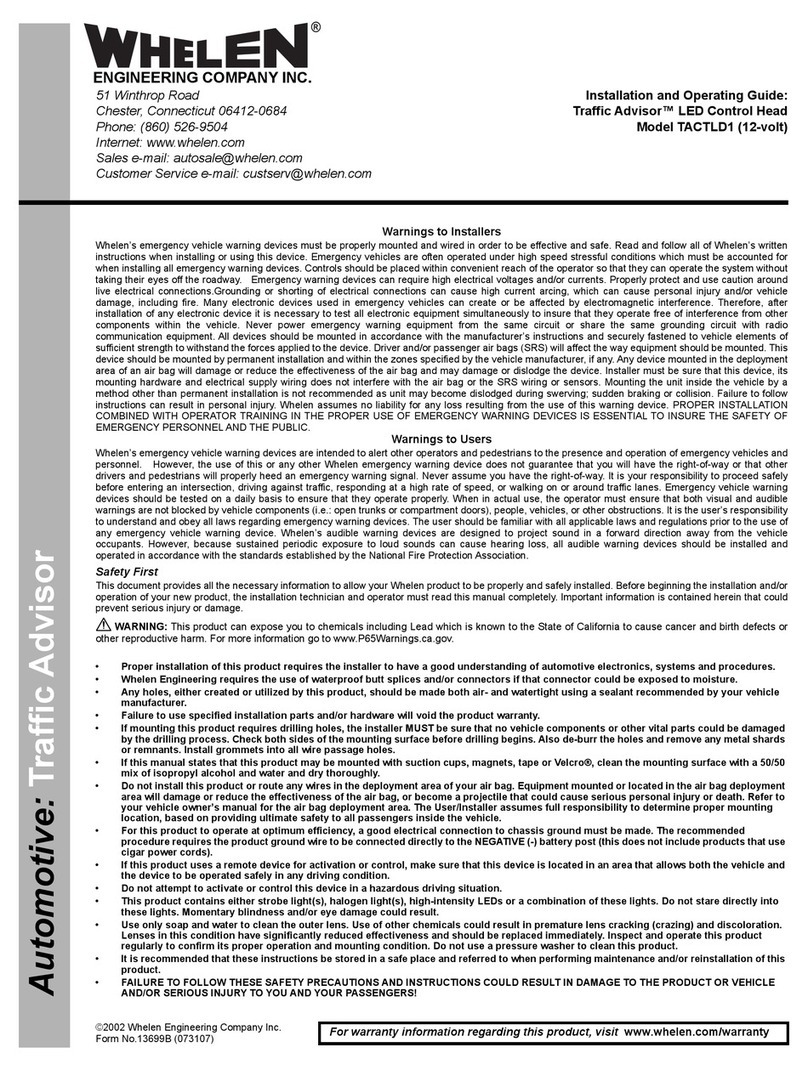
Whelen Engineering Company Traffic Advisor TACTLD1 Installation guide

Whelen Engineering Company

Whelen Engineering Company Traffic Advisor TACTLD1 Installation guide

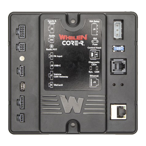
Whelen Engineering Company Core R C399R User manual

Whelen Engineering Company

Whelen Engineering Company Core R C399R User manual

Whelen Engineering Company CanTrol Basic with Traffic Advisor Troubleshooting guide

Whelen Engineering Company

Whelen Engineering Company CanTrol Basic with Traffic Advisor Troubleshooting guide

Whelen Engineering Company Core-C CCP9 User manual

Whelen Engineering Company

Whelen Engineering Company Core-C CCP9 User manual

Whelen Engineering Company CenCom Sapphire User manual

Whelen Engineering Company

Whelen Engineering Company CenCom Sapphire User manual

Whelen Engineering Company CanTrol Troubleshooting guide

Whelen Engineering Company

Whelen Engineering Company CanTrol Troubleshooting guide

Whelen Engineering Company CanTrol WC Troubleshooting guide

Whelen Engineering Company

Whelen Engineering Company CanTrol WC Troubleshooting guide

Whelen Engineering Company PCCS9N User manual

Whelen Engineering Company

Whelen Engineering Company PCCS9N User manual

Whelen Engineering Company CenCom Sapphire User manual

Whelen Engineering Company

Whelen Engineering Company CenCom Sapphire User manual

Popular Control System manuals by other brands

Draper EZ-Pad 3.0 instructions

Draper

Draper EZ-Pad 3.0 instructions

NAVIOP Loop S user manual

NAVIOP

NAVIOP Loop S user manual

Siemens SINUMERIK 828D Turning Function manual

Siemens

Siemens SINUMERIK 828D Turning Function manual

Bosch Rexroth IndraDrive Mi KCU02 instruction manual

Bosch

Bosch Rexroth IndraDrive Mi KCU02 instruction manual

Aprimatic T22 installation instructions

Aprimatic

Aprimatic T22 installation instructions

TECSYSTEM NT311 ETH instruction manual

TECSYSTEM

TECSYSTEM NT311 ETH instruction manual

Crestron PAC2M quick start

Crestron

Crestron PAC2M quick start

COMEXIO Touchpanel 2G manual

COMEXIO

COMEXIO Touchpanel 2G manual

EUCHNER MSC Installation and use

EUCHNER

EUCHNER MSC Installation and use

eSSL BG-S-105 user manual

eSSL

eSSL BG-S-105 user manual

Microengine XP-GT Series Programming manual

Microengine

Microengine XP-GT Series Programming manual

Colorbeam T021 user guide

Colorbeam

Colorbeam T021 user guide

Spike TC-100 user guide

Spike

Spike TC-100 user guide

Gefen EXT-PACS user manual

Gefen

Gefen EXT-PACS user manual

CYBELEC CybTouch Series user manual

CYBELEC

CYBELEC CybTouch Series user manual

Key Digital KD-X1000ProK operating instructions

Key Digital

Key Digital KD-X1000ProK operating instructions

CAME RBM21 - HW installation manual

CAME

CAME RBM21 - HW installation manual

Promag AG19 Hardware user's guide

Promag

Promag AG19 Hardware user's guide

manuals.online logo
manuals.online logoBrands
  • About & Mission
  • Contact us
  • Privacy Policy
  • Terms and Conditions

Copyright 2025 Manuals.Online. All Rights Reserved.