manuals.online logo
Brands
  1. Home
  2. •
  3. Brands
  4. •
  5. Whelen Engineering Company
  6. •
  7. Control System
  8. •
  9. Whelen Engineering Company PCCS9N User manual

Whelen Engineering Company PCCS9N User manual

Page 1
©1998 Whelen Engineering Company Inc.
Form No.13320D (121401)
Automotive: Sirens/Switches
For warranty information regarding this product, visit www.whelen.com/warranty
DANGER! Sirens produce extremely loud emergency warning tones! Exposure to these tones without proper and adequate hearing protection, could
cause ear damage and/or hearing loss! The Occupational Safety & Health Administration (www.osha.gov) provides information necessary to determine
safe exposure times in Occupational Noise Exposure Section 1910.95. Until you have determined the safe exposure times for your specific application,
operators and anyone else in the immediate vicinity should be required to wear an approved hearing protection device. Failure to follow this
recommendation could cause hearing loss!
• Proper installation of this product requires the installer to have a good understanding of automotive electronics, systems and procedures.
• Whelen Engineering requires the use of waterproof butt splices and/or connectors if that connector could be exposed to moisture.
• Any holes, either created or utilized by this product, should be made both air- and watertight using a sealant recommended by your vehicle
manufacturer.
• Failure to use specified installation parts and/or hardware will void the product warranty.
• If mounting this product requires drilling holes, the installer MUST be sure that no vehicle components or other vital parts could be damaged
by the drilling process. Check both sides of the mounting surface before drilling begins. Also de-burr the holes and remove any metal shards
or remnants. Install grommets into all wire passage holes.
• If this manual states that this product may be mounted with suction cups, magnets, tape or Velcro®, clean the mounting surface with a 50/50
mix of isopropyl alcohol and water and dry thoroughly.
• Do not install this product or route any wires in the deployment area of your air bag. Equipment mounted or located in the air bag deployment
area will damage or reduce the effectiveness of the air bag, or become a projectile that could cause serious personal injury or death. Refer to
your vehicle owner’s manual for the air bag deployment area. The User/Installer assumes full responsibility to determine proper mounting
location, based on providing ultimate safety to all passengers inside the vehicle.
• For this product to operate at optimum efficiency, a good electrical connection to chassis ground must be made. The recommended
procedure requires the product ground wire to be connected directly to the NEGATIVE (-)
battery post (this does not include products that use cigar power cords).
• If this product uses a remote device for activation or control, make sure that this device is
located in an area that allows both the vehicle and the device to be operated safely in any
driving condition.
• It is recommended that these instructions be stored in a safe place and referred to when
performing maintenance and/or reinstallation of this product.
• FAILURE TO FOLLOW THESE SAFETY PRECAUTIONS AND INSTRUCTIONS COULD RESULT
IN DAMAGE TO THE PRODUCT OR VEHICLE AND/OR SERIOUS INJURY TO YOU AND YOUR
PASSENGERS!
CAUTION
Loud siren noise can cause
hearing damage and/or loss.
Refer to OSHA Section 1910.95 prior
to putting ANY siren into service!
Wear
Protection!
ACTIVATION OF THIS
SIREN MAY DAMAGE
UNPROTECTED EARS!
Warnings to Installers
Whelen’s emergency vehicle warning devices must be properly mounted and wired in order to be effective and safe. Read and follow all of Whelen’s written
instructions when installing or using this device. Emergency vehicles are often operated under high speed stressful conditions which must be accounted for
when installing all emergency warning devices. Controls should be placed within convenient reach of the operator so that they can operate the system without
taking their eyes off the roadway. Emergency warning devices can require high electrical voltages and/or currents. Properly protect and use caution around
live electrical connections.Grounding or shorting of electrical connections can cause high current arcing, which can cause personal injury and/or vehicle
damage, including fire. Many electronic devices used in emergency vehicles can create or be affected by electromagnetic interference. Therefore, after
installation of any electronic device it is necessary to test all electronic equipment simultaneously to insure that they operate free of interference from other
components within the vehicle. Never power emergency warning equipment from the same circuit or share the same grounding circuit with radio
communication equipment. All devices should be mounted in accordance with the manufacturer’s instructions and securely fastened to vehicle elements of
sufficient strength to withstand the forces applied to the device. Driver and/or passenger air bags (SRS) will affect the way equipment should be mounted. This
device should be mounted by permanent installation and within the zones specified by the vehicle manufacturer, if any. Any device mounted in the deployment
area of an air bag will damage or reduce the effectiveness of the air bag and may damage or dislodge the device. Installer must be sure that this device, its
mounting hardware and electrical supply wiring does not interfere with the air bag or the SRS wiring or sensors. Mounting the unit inside the vehicle by a
method other than permanent installation is not recommended as unit may become dislodged during swerving; sudden braking or collision. Failure to follow
instructions can result in personal injury. Whelen assumes no liability for any loss resulting from the use of this warning device. PROPER INSTALLATION
COMBINED WITH OPERATOR TRAINING IN THE PROPER USE OF EMERGENCY WARNING DEVICES IS ESSENTIAL TO INSURE THE SAFETY OF
EMERGENCY PERSONNEL AND THE PUBLIC.
Warnings to Users
Whelen’s emergency vehicle warning devices are intended to alert other operators and pedestrians to the presence and operation of emergency vehicles and
personnel. However, the use of this or any other Whelen emergency warning device does not guarantee that you will have the right-of-way or that other
drivers and pedestrians will properly heed an emergency warning signal. Never assume you have the right-of-way. It is your responsibility to proceed safely
before entering an intersection, driving against traffic, responding at a high rate of speed, or walking on or around traffic lanes. Emergency vehicle warning
devices should be tested on a daily basis to ensure that they operate properly. When in actual use, the operator must ensure that both visual and audible
warnings are not blocked by vehicle components (i.e.: open trunks or compartment doors), people, vehicles, or other obstructions. It is the user’s responsibility
to understand and obey all laws regarding emergency warning devices. The user should be familiar with all applicable laws and regulations prior to the use of
any emergency vehicle warning device. Whelen’s audible warning devices are designed to project sound in a forward direction away from the vehicle
occupants. However, because sustained periodic exposure to loud sounds can cause hearing loss, all audible warning devices should be installed and
operated in accordance with the standards established by the National Fire Protection Association.
Safety First
This document provides all the necessary information to allow your Whelen product to be properly and safely installed. Before beginning the installation and/or
operation of your new product, the installation technician and operator must read this manual completely. Important information is contained herein that could
prevent serious injury or damage.
WARNING: This product can expose you to chemicals including Lead which is known to the State of California to cause cancer and birth defects or
other reproductive harm. For more information go to www.P65Warnings.ca.gov.
Installation Guide:
PCCS9N Power Control Center
51 Winthrop Road
Chester, Connecticut 06412-0684
Phone: (860) 526-9504
Internet: www.whelen.com
Sales e-mail: autosale@whelen.com
Customer Service e-mail: [email protected]
®
ENGINEERING COMPANY INC.
Page 2
WARNING!
DISCONNECTING THE VEHICLE BRAKE LAMP
CIRCUIT USING ANY SIRENS WITH RELAY OUTPUTS
OR SWITCH CONTROLLERS COULD CAUSE
VEHICLE OR PROPERTY DAMAGE, SERIOUS INJURY
OR EVEN DEATH.
DISABLING THIS CIRCUIT IS A VIOLATION OF THE
FEDERAL MOTOR VEHICLE SAFETY STANDARD
FOR THE THIRD BRAKE LIGHT, AS WELL AS REAR
BRAKE LIGHTS.
FUNCTIONS THAT BLACK OUT THE REAR BRAKE
LIGHTS (SOMETIMES CALLED “BRAKE LIGHT CUT
OUT”) MAY INTERFERE WITH THE BRAKE SHIFT
LOCK MECHANISM, AND CAUSE THE VEHICLE TO
MOVE UNEXPECTEDLY AND DANGEROUSLY.
DISCONNECTING THE BRAKE LIGHTS IN ANY WAY
IS AT YOUR OWN RISK AND IS NOT RECOMMENDED
BY WHELEN.
Page 3
LED’S For
Slide Switch
Groove on side of Aluminum
Cover used to slide in the 2
carriage bolts (Item 12) of
the mounting bracket
4 Position
Slide Switch
Push Button
Switches
Aluminum
Extruded
Cover
Backlighted
Function
Windows
The Model PCC-S9N Power Control Center is designed exclusively
to control Whelen Models 9000 and ADVANTAGE Series Lightbars
equipped with a Relay Matrix Board.
INSTALLATION
RECOMMENDATIONS
1. Remove Mounting Bracket
(Item 5) from relay/switch
box assembly (Item 1)
by loosening the two
acorn nuts (Item 12) and
sliding the mounting bracket
off the aluminum cover's
side grooves.
Choose a location for the2.
PCC-S9N and secure the
mounting bracket firmly
to the mounting surface
with customer supplied
hardware.
NOTE:
The Mounting Bracket
may be installed in any position,
as long as the relay/switch box
assembly can slide in and out from
the mounting bracket, and all switches
are easily accessible.
Wire the unit (See Pg. 2) and slide3.
the unit into position inside the mounting
bracket. Finally, tighten the two acorn nuts
(Item 12) located on each side of the PCC-S9N
PART OF
ITEM 4
DESCRIPTION
QTY.
1
REF
REF
1
1
REF
REF
REF
REF
REF
REF
REF
1
PART NUMBER
01-0285547-00
10-0340731-01
10-0340730-01
10-0121114-01
10-0320776-00
13-104320-120
07-241559-000
14-104069-080
16-1031060-04
16-1011320-20
46-0725500-00
46-0725628-00
01-0481326-00
ITEM
1
-
-
4
5
6
7
8
9
11
12
13
14
-
01-0881326-00
-
FINAL ASSEMBLY
RELAY/SWITCH BOX ASSEMBLY
LABEL, FUNCTION (W/ WHITE LETTERS)
LABEL, MADE IN THE U.S.A., FLAG
LABEL, SERIAL NUMBER
#10-24 ACORN NUT S/S
MOUNTING BRACKET, S9N
#10-24 X 1/2" CARRIAGE BOLT
#10 SPLIT LOCKWASHER
POWER INPUT PIGTAIL KIT
CONN. ASSY. MODEL PCDS9N
INSTALLATION KIT PCC-S9N
WASHER, #10 EXTERNAL TOOTH SS
PART OF
ITEM 4
1
6 7
12 11
13
14
5
Page 4
I: INTRODUCTION
The PCC-S9N is designed to operate any EDGE 9000® or
ADVANTEDGE® lightbar if equipped with an internal relay/
matrix board. In addition to controlling lightbar functions,
the PCC-S9N has a siren turn-on feature. This feature
gives the operator true single lever control over both pri-
mary warning light and siren functions on slide switch
position 3 (See pages 3 and 4). The PCC-S9N is designed
to operate on a 12 volt D.C. vehicular electrical system.
II: MOUNTING
(Also, pg. 1) When choosing a mounting location for the
PCC-S9N consider the following: The PCC-S9N should be
located so that the driver can operate the controls without
taking his eyes off the road. Interconnecting cables should
be easily accessible to facilitate installation. The PCC-S9N
is supplied with a universal mounting bracket that may be
attached either above or below the switch housing. Deter-
mine which holes in the mounting bracket are to be used,
then loosely assemble the bracket and bracket hardware
(See page 1). Slide the head of the carriage bolt into the
slot in the side of the switch housing. Position the PCC-
S9N in the desired mounting location and trace the outline
of the mounting bracket. Remove the mounting bracket
from the switch housing. Align the mounting bracket with
the outline traced in the previous step, and trace the out-
line of the mounting slots. Positioning the mounting hard-
ware (customer supplied) in the center of each mounting
slot, for maximum side to side adjustment. Attach mount-
ing bracket, and when in position tighten the acorn nuts.
III: WIRING.
The PCC-S9N is supplied with two wire
harnesses exiting the rear of the switch housing. Before
attempting any wiring, make sure all switches are in the
“OFF” position. The slide switch must be in the full left
position and all push buttons must be in fully extended
position.
A. The nine wire harness is designed to plug directly into
the end of an EDGE® or ADVANTEDGE® lightbar cable
equipped with a mating connector. If retro-fitting a lightbar
not supplied with a mating connector, crimp AMP pins
(Whelen part number 39-0501316-04) on the wire ends
and insert them into an AMP nine pin connector (Whelen
part number 39-0409313-04). Make sure the wire colors
match up when the connectors are mated.
B. The four wire harness from the switch housing has a
mating harness supplied in kit form. The loose black/white
wire and the white/green wire should only be inserted into
the connector if their functions are used (see page 3).
1. The black/white wire is the +12 VDC (positive) output
from push button switch #6 and is rated at 250 mA. An
external relay (not supplied) is recommended for the use
of this circuit. If you wish to use this feature, insert the
loose black/white wire into the connector in position #4.
For ON-OFF operation use Bosch relay 0 332 014 150
(Whelen part number 30-1712001-08) or equivalent. For
HORN/SIREN operation use Bosch relay 0 332 204 150
(Whelen part number 30-2612021-08) or equivalent. (Pg.
3 wiring)
2. The supplied white/green wire assembly is an auxiliary
output from the slide switch position #3 (red led indicator).
Its purpose, when connected to a Whelen siren amplifier,
is to turn on both the siren and a primary warning light
function when the slide switch is operated in position #3.
The siren tone is determined by the setting of the siren
function control knob. Refer to your siren amplifier’s
installation manual to learn how to utilize this feature.
3. Connect the black wire to a good electrical ground
(NEGATIVE).
4. The red wire is the power feed for switches 2 through
7, as well as the red/green led indicators for these
switches. This wire should be connected to the vehicle
fuse block “ACCESSORY OUTLET”. This circuit is fused
on the relay board at 5 amps with fuse F1. (See page 5).
Failure to use the “ACCESSORY OUTLET” will cause the
led indicators to remain on, and drain the vehicle battery.
IV: OPERATION
With all electrical connections made, and the vehicle
accessory outlet “ON”, the PCC-S9N will display the fol-
lowing characteristics: Slide switch LED indicators will be
off, and green LED indicators will be lit behind the func-
tion windows located above the push button switches. As
the slide switch is moved progressively to the right, the
green, yellow and red LED indicators will turn on in
sequence, as well as the corresponding lightbar func-
tions. As each push button switch is depressed, the green
LED indicator will change to red and the corresponding
lightbar function will turn on.
NOTE: Switch #7 is a momentary contact switch for
strobe low power, and will work only if the lightbar strobe
lights are operating. Switch #7 will display a red indicator
only while pressed in, however the strobe lights will oper-
ate in low power until the power to the strobe lights is
turned off. Turning the strobe lights off and then on, will
reset the high power function.
V: FUNCTION LABELS:
The PCC-S9N is supplied with an assortment of com-
monly used function labels. Verify the function of each
switch. Peel the labels from the backing sheet and stick
on the front of the appropriate switch function window.

Page 5
SEE PAGE5FOR
WIRECOLORS
RED WIRE /POSITION 1
AMP 4
POSITION
SOCKET
CONNECTOR
AMP9POSITION SOCKETCONNECTOR.
CONNECTS TO9WIRECABLEHARNESS
OF THE 9000 ORADVANTAGELIGHTBAR.
®®
PCC-S9NPOWERINPUTPIGTAIL
KITNUMBER46-0725500-00
AMP 640392 SOCKET
WHITE/GREEN WIRE,POSITION 3
BLACK/WHITEWIREPOSITION 4
THE REDAND BLACKWIRESARE
FACTORYINSERTEDIN THE AMP
4POSITION PIN CONNECTOR
THE WHITE/GREEN WIRETOBE
INSERTEDIN THE CONNECTOR,
ONLYIFTHE AUXILIARYSIREN
ENABLEISTOBEUTILIZED.
THE BLACK/WHITEWIREISTO
BEINSERTEDINTOCONNECTOR
ONLYIFTHE SYSTEMISTOBE
CONNECTEDTOABOSCHRELAY.
DONOT
CONNECT EITHEROF THESE
TWOWIRESTOCONNECTOR,
IF ANY OF THESEWIRING
OPTIONSARENOTDESIRED!
IMPORTANT NOTE:
TOACCESSORYOUTLET
TOGROUND.NEGATIVE (-)
AUXILIARYSIREN ENABLE
12
34
BLACKWIRE /POSITION 2
87
30
85
86
87A
BLACK/WHITEWIRETOBECONNECTED
TOTHE TWORELAYOPTIONSSHOWNABOVE.
TOGROUND
TOHORN
BUTTON
TOHORN
TOSIREN
AUXILIARY
SWITCHWIRE
CONTROL OPTION “B” SPDT BOSCH RELAY, PART # 0332 204 150
BLACK/WHITE WIRE IS USED FOR HORN/SIREN OPERATION.
CONTROLED BY SWITCH #6.
CONTROL OPTION “A” SPDT BOSCH RELAY, PART # 0332 014 150
BLACK/WHITE WIRE IS USED FOR ON-OFF OPERATION.
CONTROLED BY SWITCH #6.
87A
86
85
30 87
TOOPTIONAL EQUIPMENT, 30 AMP MAXIMUM.
POSITIVE 12 VDC.
GROUND
TOPOSITIVE (+)12VDC,
TOBEFUSED APPROPRIATLY.
4Position
Slide Switch
Numbered 1,
with 3LED’s.
5 SPST Push Button
Switches, Numbered
from 2 to 6.
PCC-S9N FRONT VIEW
1 SPST Momentary
Contact Push Button
Switch.Numbered 7.
6Function Windows.
Backlighted by Red/Green LED’s.
GREEN
YELLOW
RED
S2 S3 S4 S5 S6 S7
Whelen Engineering recommends you return
the PPC-S9N Power Control Center to our
Repair and Service Department if it malfunc-
tions. The slide switch and the six push button
switches are protected by two separate 5 amp
fuses soldered into position on the PC board, F1
and F2 (See Pg. 5). Unauthorized field repairs
and/or the substitution of original parts with
unauthorized repair parts, may cause further
damage and VOID THE WARRANTY.
WIRING for the PCC-S9N
POWER CONTROL CENTER
with CONTROL OPTIONS
Page 6
NOTE:Itis reccommended
before attempting any wiring
to have all switches in the
“OFF” position.Slide switch
must be in the FULL LEFT
position and all push button
switches must be inthe
FULLY EXTENDED position.
PCC-S9N
SWITCHSYSTEM
SCHEMATIC
BC337
DS1
GRN
DS2
YEL
DS3
RED
OFF
4 POSITION
SLIDE SWITCH
SWITCH 1
S2 S3 S4
DS4 DS5 DS6
RED/GREEN
LED
RED/GREEN
LED
RED/GREEN
LED
S5
DS7
RED/GREEN
LED
S6
DS8
RED/GREEN
LED
S7
DS9
RED/GREEN
LED
S1
Q1
R4
1.5K
R5
10K
R1
1K
R2
1K
R3
1K
D1
1N4005
R6
680
D2
1N4005
D3
1N4005
D4
1N4005
D5
1N4005
D6
1N4005
R7
680
R8
680
R9
680
R10
680
R11
680
SEE IMPORTANT NOTE On Bottom of Page 3Concerning
the WHITE/GREEN WIREand the BLACK/WHITEWIRE
Enclosed Inside the PCC-S9NPower Input Pigtail Kit.
NOTE:UNLESS OTHERWISESPECIFIED, RESISTORS AREINOH
MS, 1/4W+/-5%.
6RED/GREEN LEDS LOCATEDBEHINDTHE FUNCTION WINDOWS, ON THE
FACEPLATEOFTHE UNIT,ABOVE THE 6 SPST PUSHBUTTON SWITCHES.
GREEN POS 1 (P1-1)
GREY POS 2 (P1-5)
BLUE POS 3 (P1-4)
WHITE /GREEN
SIREN ON (P2-3)
BLACKGND (P2-2)
RED +12V (P2-1)
WHITE (P1-6)
YELLOW(P1-7)
ORANGE (P1-8)
BLK/WHITE (P2-4)
VIOLET (P1-3)
F1/5AMP
PICO FUSE
BROWN+12V (P1-2)
SWITCH2SWITCH3SWITCH4SWITCH5SWITCH6SWITCH7
WHITE /BLK(P-19)
3LEDS LOCATEDABOVE THE 4 POSITION SLIDESWITCH
GRN
YEL
RED
VIOLET
PUSHSWITCH7(Momentary)
3
ORANGE
PUSHSWITCH5
8
YELLOW
PUSHSWITCH4
7
WHITE
PUSHSWITCH3
6
WHITE-BLACK
PUSHSWITCH2
9
BLUE
SLIDE SWITCHPOSITION 3
4
GREY
SLIDE SWITCHPOSITION 2
5
GREEN
SLIDE SWITCHPOSITION 1
1
BROWN
+12 POWER FEED
2
RED
POSITIVE (+) 12 VDC
1
BLACK
NEGATIVE (-) GROUND
2
WHITE-GREEN
SIREN ON
3
BLACK-WHITE
PUSHSWITCH6
4
P9 9 POSITION SOCKET CONNECTOR
(SOCKET POSITION NUMBERS LISTED)
AMP 4 POSITION SOCKET CONNECTOR
(SOCKET POSITION NUMBERS LISTED)
F2/5AMP
PICO FUSE
FOR SLIDE SWITCH
FUNCTIONS &
INDICATORS
(SEE TEXT)
(SEE TEXT)
POWER FEED FOR
PUSHBUTTON
SWITCHES &
BACKLIGHTING
(INTERNAL)
(INTERNAL)

Other Whelen Engineering Company Control System manuals

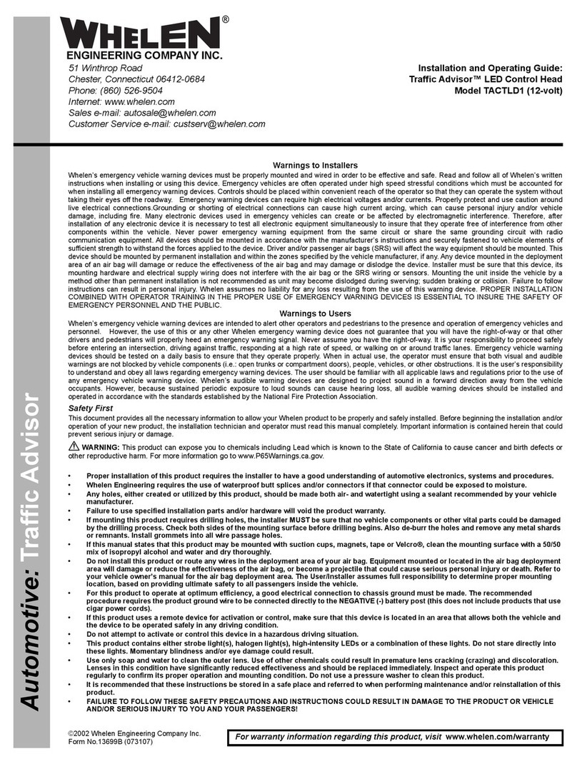
Whelen Engineering Company Traffic Advisor TACTLD1 Installation guide

Whelen Engineering Company

Whelen Engineering Company Traffic Advisor TACTLD1 Installation guide

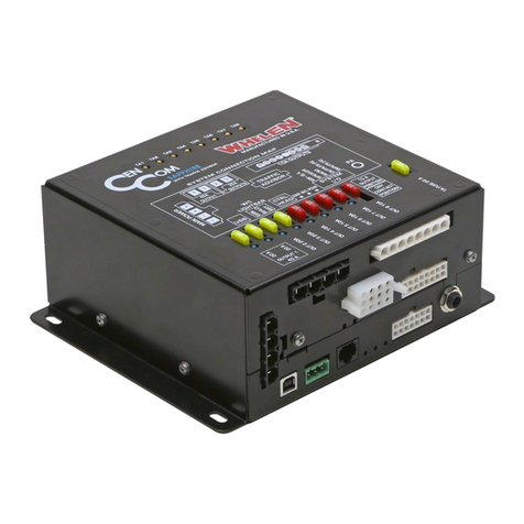
Whelen Engineering Company Core-C CCP9 User manual

Whelen Engineering Company

Whelen Engineering Company Core-C CCP9 User manual

Whelen Engineering Company PCCS9R User manual

Whelen Engineering Company

Whelen Engineering Company PCCS9R User manual

Whelen Engineering Company CanTrol Troubleshooting guide

Whelen Engineering Company

Whelen Engineering Company CanTrol Troubleshooting guide

Whelen Engineering Company CanTrol Basic with Traffic Advisor Troubleshooting guide

Whelen Engineering Company

Whelen Engineering Company CanTrol Basic with Traffic Advisor Troubleshooting guide

Whelen Engineering Company CenCom Sapphire User manual

Whelen Engineering Company

Whelen Engineering Company CenCom Sapphire User manual

Whelen Engineering Company CenCom Sapphire User manual

Whelen Engineering Company

Whelen Engineering Company CenCom Sapphire User manual

Whelen Engineering Company CanTrol WC Troubleshooting guide

Whelen Engineering Company

Whelen Engineering Company CanTrol WC Troubleshooting guide

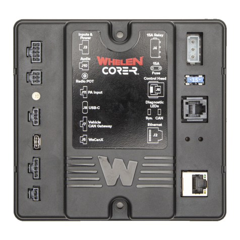
Whelen Engineering Company Core R C399R User manual

Whelen Engineering Company

Whelen Engineering Company Core R C399R User manual

Popular Control System manuals by other brands

Chamberlain PILCEV user manual

Chamberlain

Chamberlain PILCEV user manual

Airzone VAF BLUEFACE user manual

Airzone

Airzone VAF BLUEFACE user manual

Johnson Controls VMA1200 Series Technical bulletin

Johnson Controls

Johnson Controls VMA1200 Series Technical bulletin

HWH 625 Series Operator's manual

HWH

HWH 625 Series Operator's manual

YASKAWA VIPA System 300S manual

YASKAWA

YASKAWA VIPA System 300S manual

SILENT KNIGHT INTELLIKNIGHT 5820XL Sales guide

SILENT KNIGHT

SILENT KNIGHT INTELLIKNIGHT 5820XL Sales guide

Fancom FB.1 manual

Fancom

Fancom FB.1 manual

Crestron SmartPresenter SP-1 Operation guide

Crestron

Crestron SmartPresenter SP-1 Operation guide

OBSIDIAN CONTROL SYSTEMS NETRON DMX10 installation guide

OBSIDIAN CONTROL SYSTEMS

OBSIDIAN CONTROL SYSTEMS NETRON DMX10 installation guide

Elstat ems75vr Installation and user guide

Elstat

Elstat ems75vr Installation and user guide

Juniper JCS1200 Hardware guide

Juniper

Juniper JCS1200 Hardware guide

Siemens QAW10 operating instructions

Siemens

Siemens QAW10 operating instructions

GoFlight GF-THR Operating handbook

GoFlight

GoFlight GF-THR Operating handbook

Honeywell VR9105V installation instructions

Honeywell

Honeywell VR9105V installation instructions

Smart temp EASY ZONE TOUCH user manual

Smart temp

Smart temp EASY ZONE TOUCH user manual

HWH SPACEMAKER 325 Series Operator's manual

HWH

HWH SPACEMAKER 325 Series Operator's manual

Tyco AMD-1 quick start guide

Tyco

Tyco AMD-1 quick start guide

Mountz MDC-26 Operation manual

Mountz

Mountz MDC-26 Operation manual

manuals.online logo
manuals.online logoBrands
  • About & Mission
  • Contact us
  • Privacy Policy
  • Terms and Conditions

Copyright 2025 Manuals.Online. All Rights Reserved.