Page 2
The ISP4HS™ is a versatile strobe power supply serving as the
fundamental building block for many Whelen emergency warning
systems. The ISP4HS™ is used in the state-of-the-art Fast Trax™
lighting system, as well as the industry standard DOT systems
pioneered by Whelen. In addition, the ISP4HS™ serves equally
well as a stand alone synchronized strobe power supply and
halogen flasher known as the Whelen SSNF systems.
Programming for the various applications is selectable by a 4
position dip switch. 5 low current control lines allow flexible
operator control and the system may be wired as simple or
intricately as the users needs dictate.
When used in a stand-alone or DOT application, both the strobe
and halogen outlets have Hi / Low intensity control. This may be
wired for either latched or level control and the power supply will
automatically sense which wiring has been selected and
automatically adjust it’s internal circuitry.
Another feature is the optional Diagnostix™ display. This allows
the operator to confirm proper operation of the system in “real
time” and diagnose system malfunctions. When used in a Fast
Trax or standard DOT system, please refer to the system wiring
instructions for the default wiring of the ISP4HS™, applicable to
your system.
WARNING: The Strobe Light Power Supply is a high voltage
device. Do not touch or remove tube assembly in strobe light
head assemblies while in operation. Wait 10 minutes after
disconnecting the unit from its power source before starting work
or troubleshooting on power supply or system.
CAUTION: As it will be necessary to drill holes into the mounting
surface, the installer MUST be sure that no vehicle components or
other vital parts could be damaged by the drilling process. Check
both sides of the mounting surface before drilling begins!
WARNING: All customer supplied wires that connect to the
positive terminal of the battery must be sized to supply at
least 125% of the maximum operating current and FUSED at
the battery to carry that load. DO NOT USE CIRCUIT
BREAKERS WITH THIS PRODUCT! (See wire chart, this page)
Selecting a Mounting Location:
The most common choice for a mounting area would be a trunk or
similar compartment. However, due to the wide variety of vehicles
onto which the unit could be installed, this is not always possible.
The following guidelines will help the installer select an acceptable
alternative.
• The power supply should be mounted on a metal surface
to aid heat dissipation. Be sure that this surface is not
one that either generates or is exposed to excessive heat
during normal operation of the vehicle.
• Do not select a location where the unit will be exposed to
potential damage from any unsecured or loose
equipment in the vehicle.
• Do not allow the unit to be exposed to water.
• When routing the power supplies wires, it is important to
choose a path that will keep these wires away from
excessive heat and from any vehicle equipment that
could damage the wires (trunk lids, door jams, etc.).
Mounting your ISP4HS:
1. Position the ISP4HS in its proposed mounting location to
ensure that it fits properly. With the unit in place, insert an awl
or other suitable tool into the mounting holes of the power
supply and scribe the areas to be drilled.
2. Remove the unit from its mounting area and, using a drill bit
sized for a #10 sheet metal screw, drill a hole in each of the
areas scribed in the previous step.
3. Return the power supply to its mounting location and using
the supplied screws, mount the unit.
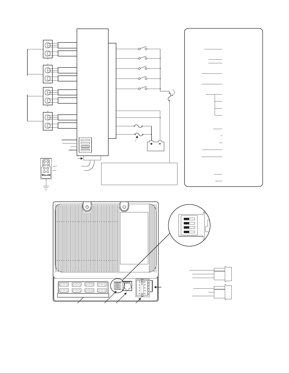
Wiring your ISP4HS:
1. Locate the 10 position Input Connector included with your
ISP4HS and plug it into the port indicated on page 3. Extend
the 2 BLACK wires, the RED wire and the WHITE wire from
the Input Connector towards the battery.
2. Connect the RED wire to a fuse block (customer supplied)
and then to the POSITIVE terminal on the battery.
3. Connect the WHITE wire to a fuse block (customer supplied)
and then to the POSITIVE terminal on the battery.
NOTE: Although a 15 amp fuse (customer supplied) is
required to be used in the fuse block, do not install the fuse
until all wire connections are completed.
4. Connect the BLACK wires to the factory chassis ground
adjacent to the battery.
5. Refer to diagram on page 3 for wiring information for the
remaining Switch Control Wires and Pattern Control Wires.
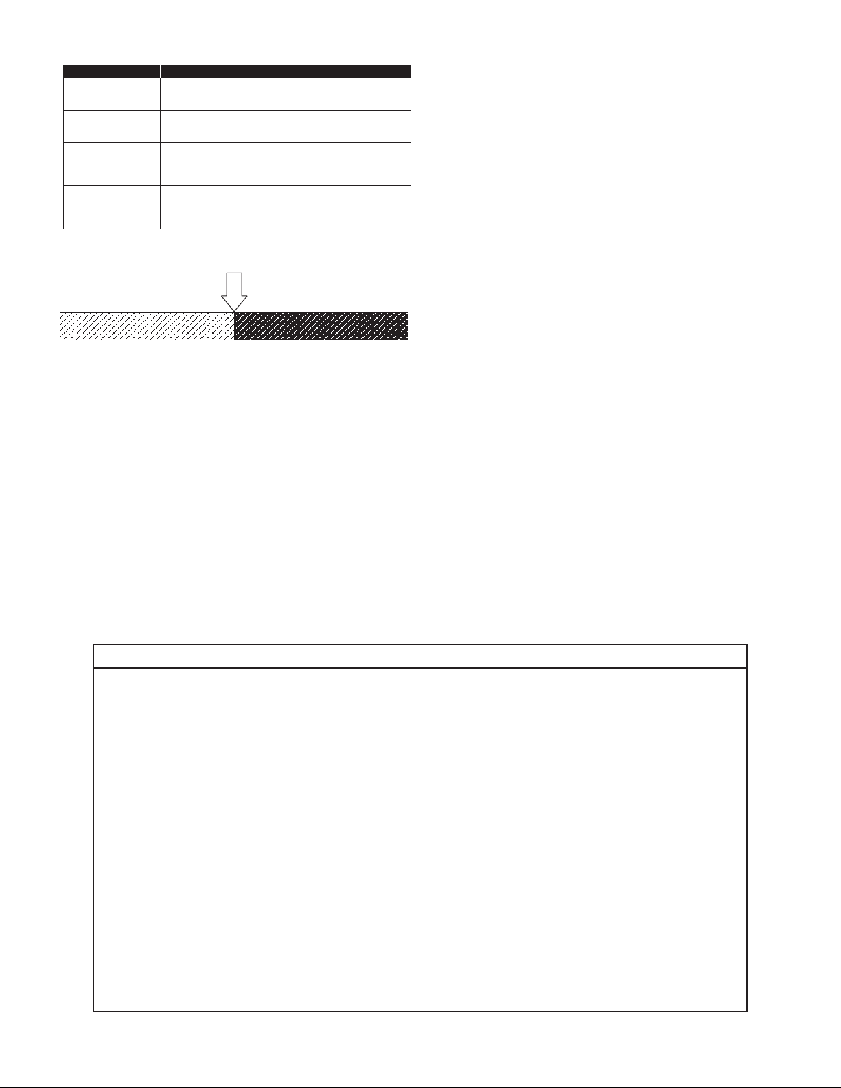
RECOMENDED SIZE / CUSTOMER SUPPLIED WIRES
POWER AND GROUND CONTROL LINES
18AWG . . . . . .5 FT. MAX 22 AWG . . . . 5 FT. MAX
16 AWG . . . . . .8 FT. MAX 20 AWG . . . . 16 FT. MAX
14 AWG . . . . . .13 FT. MAX 18 AWG . . . . 26 FT. MAX
12 AWG . . . . . .21 FT. MAX 16 AWG . . . . 41 FT. MAX
10 AWG . . . . . .33 FT. MAX