Whip Mix Xcavator User manual

Xcavator™
User Manual
Whip Mix Corporation •361 Farmington Ave. •P.O. Box 17183 •Louisville, KY 40217-0183 USA
502-637-1451 •800-626-5651 •Fax 502-634-4512 •www.whipmix.com
Patent Pending

Xcavator
Operating Instructions
2
Intended Purpose
The Whip Mix Xcavator is designed to automatically remove
95% of the volume of investment mold material surrounding
pressed ceramic restorations where manual divestment would
typically be done. When used as directed, the unit will
significantly shorten the total process time required to go from
press oven removal to pattern retrieval. The unit can be run
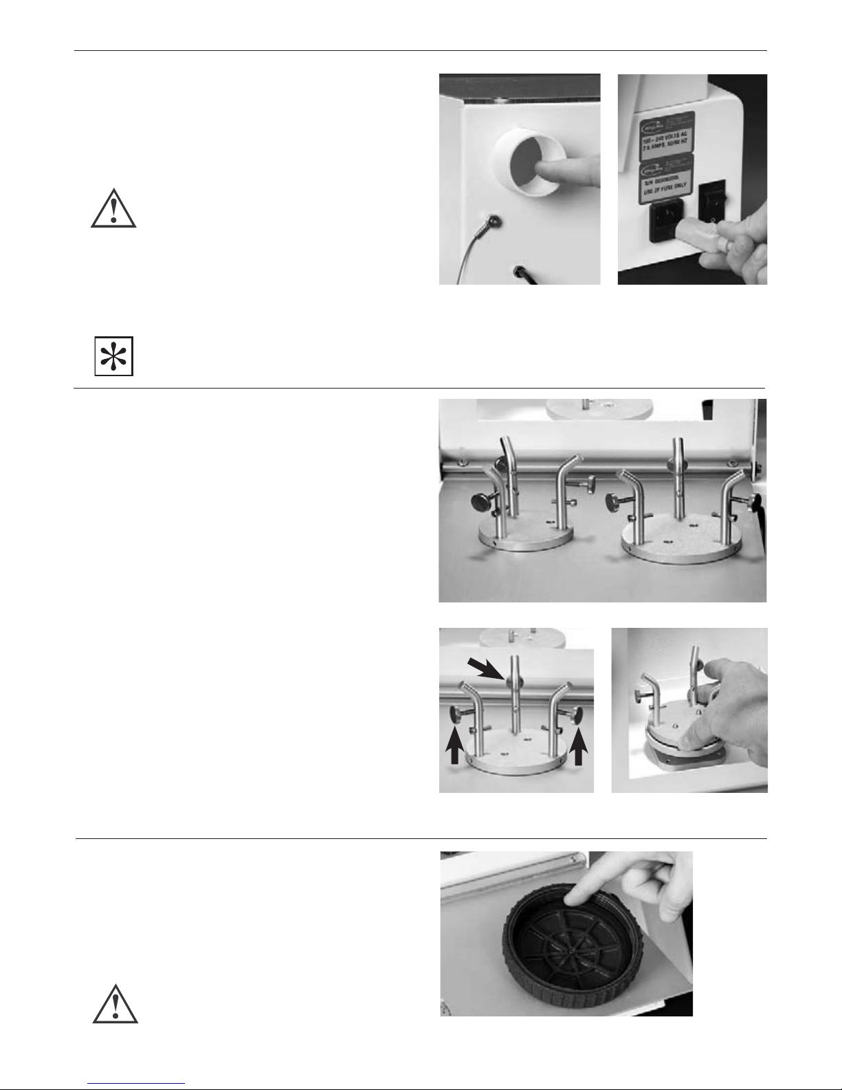
Grounding
The high velocity flow of glass beads across plastic or
metal surfaces will charge the beads and the surfaces they
flow over. Great pains have been taken to ground every
component in the Xcavator to insure equalization of static
electrical charges. The power cord and the outlet the unit
is plugged into must have 3 prongs to insure the presence
of the earth ground which is vital to the prevention of static
electrical charge buildup. If, for any reason, you receive a
static electrical shock from any part of the equipment, you
should verify the integrity of the grounded outlet the unit is
plugged into, or call an electrician. Operating the unit
ungrounded can result in painful shocks to the operator
and damage to the electronics of the unit itself.
Never cut the ground stud off the power cord or plug
the unit into a 2 lead extension cord or outlet.
Dry Air Supply
All compressed air condenses moisture in the air lines as
a result of the physics of gas compression. This moisture
can accumulate in low areas of the air piping even if there
is a master air dryer at the compressor.
It is recommended that a cartridge type dryer be placed
just before the air regulator of the unit. If moist air enters
the unit it will collect in the reservoir and cause clumping
of beads and disrupt the critical air/bead ratio needed
for consistent divestment. It can also plug up either the
reservoir output orifice or the bead/air injector inside
the injector block and cause inconsistent divestment.
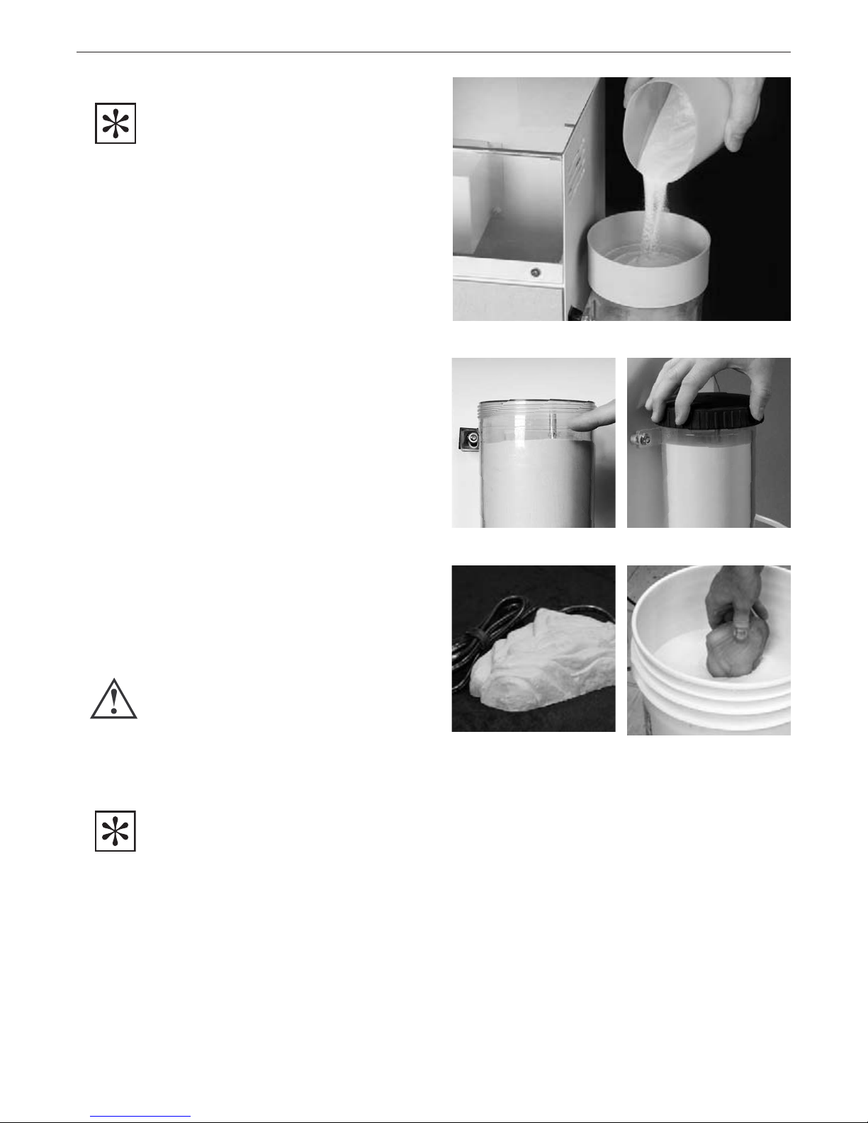
Dry Bead Supply
The strainer supplied with the Xcavator serves two purposes;
(1) it eliminates clumped beads and foreign debris which
could clog the bead transport system, (2) it validates/
invalidates the dryness of the beads. If the beads will not
pass through the strainer without tapping or shaking the
strainer, then they are too moist to be transported reliably.
A five watt heater is supplied with the Xcavator to be
placed fully submerged in the bead storage container. It
will raise the temperature of the beads to about 5°above
the room temperature. This gentle warming will drive off
any moisture the beads might accumulate and insure they
will transport reliably.
Treat Pressurized Components With Care
Never strike the bead jar or pull on the connecting air
tubing while the system is pressurized. This can result in
cracking the plastic jar or wind up spraying glass beads or
plastic debris around the area and pose a safety hazard.
Particulate Exposure
Never open the cabinet door while a divestment cycle is
in progress. The exhaust system will pull the dust cloud
towards the rear of the cabinet, but air conditioning/heating
convection currents in the room could cause a portion
of the dust cloud to escape into the room and pose a
possible health risk.
Handling of Hot Investment Molds
Always use laboratory tongs to handle hot investment molds
and cautiously test the temperature of divested molds before
you attempt to remove divested molds from the cabinet.
Exhaust Flow Volume
The built-in vacuum sensor will prohibit divesting unless
the vacuum flow is sufficient to remove the airborne dust
rapidly. If you are having dust cloud removal issues check
your vacuum unit or central vacuum flow to ensure removal
of the fine dust.
Divesting Media Composition
and Particle Sizes
Use only 50–100 micron glass beads with the Xcavator
for the following reasons:
1. Other material types may be harder than glass
beads and damage the porcelain work product.
2. Other material sizes may alter the depth of cut,
and/or the cut channel width.
unattended and will alert the operator when an investment mold
is divested to allow efficient processing and labor usage.
The unit employs state of the art robotic precision to
ensure consistent material removal time after time.
The Xcavator is easy to operate, ergonomically friendly
and compact enough to earn its place on a work surface
in the casting room.
Important Topics for Safe, Reliable Operation
IMPORTANT NOTE: THE XCAVATOR PRODUCT HAS BEEN
EXHAUSTIVELY TESTED WITH WHIP MIX BRAND 50 MICRON GLASS
BEAD MEDIA. FOR BEST AND MOST RELIABLE DIVESTING RESULTS
WE STRONGLY RECOMMEND YOU USE WHIP MIX BRAND BEADS.
WHIP MIX BEADS FLOW MORE RELIABLY, AND ARE LESS PRONE
TO CLUMPING DURING HIGH HUMIDITY CONDITIONS.
THE USE OF ALUMINUM OXIDE (ALOX), BEADS IS NOT RECOMMENDED
FOR USE WITH THE XCAVATOR. ALOX BEADS WILL POTENTIALLY
CAUSE DAMAGE TO YOUR PORCELAIN BECAUSE THEY ARE HARDER
THAN THE PORCELAIN. ALOX WILL ALSO CAUSE PREMATURE
WEARING OUT OF THE QUARTZ NOZZLE.

Xcavator
Operating Instructions
3
Familiarization
Control Panel
Access Door
1. Ready indicator
2. 100 Gram cycle start key (cool mold)
3. 200 Gram cycle start key (cool mold)
4. 100 Gram time delay before start indicator (hot mold)
5. 200 Gram time delay before start indicator (hot mold)
6. Abort cycle key
7. Exhaust flow Indicator
8. Depth of cut selector switch
Setup
Air Supply
1. Connect your compressed air supply to the air regulator
inlet hole shown in the photograph (Figures 1A and 1B).
The inlet hole is a standard 1/8" National Pipe Thread (NPT).
Air Regulator
Setpoint Adjust
2. With air supply connected, pull knob upward, and
rotate it until gauge needle points to 35 psi (Figure 2).
NOTE: THIS MAY NEED TO BE RE-ADJUSTED SLIGHTLY
ONCE BEAD FLOW IS ESTABLISHED.
Push knob back downward after pressure is set.
Daily Moisture Bowl Check
3. Pressing upwards on the black plastic ring at the bottom
of the air regulator opens up a check valve and allows
accumulated moisture to drain from the clear plastic
accumulator bowl (Figure 3). It is very important to keep
drained so that moisture does not pass through to the
bead reservoir. Moist beads will adhere to each other
and prevent transfer to the nozzle.
1
2 6
3
7
4
8
5
Figure 2 Figure 3
Figure 1A Figure 1B

Xcavator
Operating Instructions
4
Checking Reservoir Gasket
1. Please note the gasket in the lid of the reservoir.
It is important to keep this gasket and the mating
rim of the reservoir wiped free of beads to insure a
good air pressure seal (Figure 9). The threads in the
lid should also be wiped with a DRY cloth or brush
to remove beads accumulating in the threads.
CAUTION: NEVER USE A WET CLOTH AS THE MOISTURE WILL
GET INTO THE RESERVOIR AND CAUSE TRANSFER PROBLEMS.
Chuck Assemblies
1. There is a dedicated chuck assembly for each nominal
mold size (100 & 200 gram molds) (Figure 6). The chucks
are easily exchanged as work load dictates.
Chuck Assembly Setup
2. Before using the divester make sure the three thumbscrews
are pre-adjusted for the type of ring-former system you
use (Figure 7). If you use tapered ring-formers place
a tapered investment mold in the chuck and adjust the
thumbscrews inward until they contact the investment.
Then withdraw them one full turn to allow enough
clearance for the hot mold to slip into the chuck without
interference which might cause you to lose your grip
on the ring with the tongs.
If you use both tapered and untapered rings of each size
you will want to purchase additional chuck assemblies
so that you don’t have to constantly re-adjust the thumb
screws. (See spare parts list in back of manual.)
Chuck Assembly Installation
3. Select one of the two furnished chuck assemblies
(100 gram or 200 gram) and place it over the two guide
pins on the mounting plate inside the cabinet (Figure 8).
Setup (continued)
Exhaust Port
4. Connect your central vacuum system or
dedicated vacuum unit to the rear of the
cabinet as shown (Figure 4).
CAUTION: NEVER OPERATE THE XCAVATOR UNIT WITHOUT
SUCTION INSIDE THE CABINET TO PREVENT HUMAN EXPOSURE
TO FINE PARTICULATE MATTER WHICH CAN BE HAZARDOUS TO
YOUR HEALTH.
Power
5. Connect the furnished power cord to the unit and
then to any grounded AC outlet capable of furnishing
15 amps (standard branch breaker size) (Figure 5).
NOTE: POSITION THE UNIT LEAVING ENOUGH SPACE AROUND
THE LEFT HAND SIDE OF THE CHASSIS SO YOU CAN EASILY
REACH THE MAIN ON/OFF SWITCH.
Figure 6
Figure 9
Figure 7 Figure 8
Figure 4 Figure 5
100 gram
200 gram

Xcavator
Operating Instructions
5
Filling Jar
IMPORTANT NOTE:
THE XCAVATOR PRODUCT HAS BEEN EXHAUSTIVELY TESTED
WITH WHIP MIX BRAND 50 MICRON GLASS BEAD MEDIA. FOR
BEST AND MOST RELIABLE DIVESTING RESULTS WE STRONGLY
RECOMMEND YOU USE WHIP MIX BRAND BEADS. WHIP MIX
BEADS FLOW MORE RELIABLY, AND ARE LESS PRONE TO
CLUMPING DURING HIGH HUMIDITY CONDITIONS.
THE USE OF ALUMINUM OXIDE (ALOX), BEADS IS NOT
RECOMMENDED FOR USE WITH THE XCAVATOR. ALOX BEADS
WILL POTENTIALLY CAUSE DAMAGE TO YOUR PORCELAIN
BECAUSE THEY ARE HARDER THAN THE PORCELAIN. ALOX
WILL ALSO CAUSE PREMATURE WEARING OUT OF THE
QUARTZ NOZZLE.
1. Remove the lid of the reservoir by rotating it by hand
counter-clockwise. Place the strainer over the rim of
the reservoir and pour the new beads into the strainer
slowly, allowing time for the beads to pass through
(Figure 10). Always use the strainer when filling the jar
to eliminate clusters of beads, which will cause the
unit to malfunction. Enclosed with your Xcavator
unit is a 5 Watt heater to help eliminate moisture
in your bucket of beads. Plug in the 5 Watt heater
and submerge it below the surface of the Xcavator
bead storage bucket to insure that beads will flow
through the strainer and transport reliably to the
nozzle. Fill the jar with 50–100 micron glass beads up
to the maximum fill line on the jar, then replace the jar lid
by screwing it clockwise, then snugging it firmly closed
by hand (Figures 11 and 12).
IMPORTANT: NEVER OVERFILL THE JAR AS THE
BEADS REQUIRE AT LEAST A HALF INCH OF
HEAD SPACE TO ALLOW ROOM FOR AERATING
THE BEADS SO THAT THEY WILL TRANSFER.
CAUTION: IF THE LID CANNOT BE REMOVED BY HAND AFTER
THE UNIT HAS BEEN PRESSURIZED DURING A DIVESTMENT
CYCLE, MAKE SURE THE AIR FLOW NOISE HAS STOPPED AND
allow 30 seconds to allow any residual air pressure
inside the jar to bleed off THROUGH THE NOZZLE. IF YOU
CANNOT FEEL OR HEAR ANY AIR AT THE NOZZLE AND
THE LID STILL WILL NOT RESPOND TO HAND LOOSENING,
CONSULT THE TROUBLESHOOTING SECTION AT THE
REAR OF THIS MANUAL.
IMPORTANT NOTE:
IF THE BEAD MEDIA DOES NOT FLOW FREELY THROUGH
THE STRAINER, THIS IS AN INDICATION OF EXCESSIVE
MOISTURE CONTENT. MOIST BEADS WILL ADHERE TO
EACH OTHER AND NOT FREELY SEPARATE FROM EACH
OTHER AND FALL THROUGH THE STRAINER. THEY WILL
CAUSE INTERMITTENT OR EVEN COMPLETE STOPPAGE
OF TRANSPORT FLOW TO THE JET NOZZLE. THE 5 WATT
HEATER PLACED IN THE BEAD BUCKET WILL HELP
PREVENT THIS MOISTURE ACCUMULATION.
Figure 10
Figure 11
Figure 13
Figure 12
Figure 14

Xcavator
Operating Instructions
6
Theory Of Operation
The Xcavator is designed to remove 95 percent of
investment material from a 100 gram or 200 gram
investment mold unattended. It will shorten the
overall press to pattern recovery time significantly.
Instead of removing a hot mold from your pressing furnace
and waiting up to 50– 60 minutes for it to cool to a safe
bare hand handling temperature then spending another
Controlling the Depth of Cut
There are four factors which affect the depth of cut
in a given mold:
1. Air Pressure
2. Spindle Rotation Speed
(as set by the Depth of Cut Knob)
3. Density of Investment Material AND
Concentration of Special Liquid.
4. Bead Media Size and Hardness
As a rule of thumb, the air pressure should be set to the
lowest psi value that will yield satisfactory cuts throughout
the range of investment brands and concentrations by
adjusting ONLY the 16 position spindle speed selector
knob. Whip Mix has determined that 35 psig is the
pressure setting which will cover the entire spectrum
of currently available brands and concentrations. The
hardest and highest density investment should be run on a
Depth of Cut setting towards the higher numbered positions
while less dense investments should be run on the lower
numbered settings.
An Important Note
Regarding Air Pressure
Even though the incoming air pressure is perhaps
higher than you would normally select for manual
divestment, the direct comparison is not physically
valid for the following reason; when manually divesting
the nozzle is within less than a centimeter of the glass
pattern. The Xcavator jet nozzle NEVER comes within
2–3 centimeters of the glass pattern and is in
CONSTANT MOTION, making it impossible to dwell over
any given spot on the glass pattern for more than a few
seconds. The increased distance effectively drops the
pressure level of the air propelling the beads so that by
the time they reach the glass pattern the kinetic energy
the beads transfer to the glass is actually less than with
a manual divester.
You should use only one type and size of bead media. In
practice, the only one of these interactive factors remaining
variable should be the Depth of Cut Selector knob.
How Does it Work?
The Xcavator uses a robotic grade precision stepper motor
to digitally turn the investment mold in an ultra-precise rate
of rotation. This rotation is computer controlled to spin
slowly at the outside periphery of the mold and slowly
accelerate as the swing arm approaches the center of the
mold rotation. This precision is the key to controlling the
depth of cut and the uniformity of material removal
across the horizontal material removal plane.
The nozzle swing arm is also controlled by a robotic
grade precision stepper motor to digitally position
the nozzle along each concentric cutting track with
minimal overlap and high repeatability.
5–15 minutes to hand divest, you can remove the mold
from the press furnace, press the corresponding delay cycle
button and the Xcavator will announce when the mold is 95
percent divested with a beeping sound, and the green
Ready light will be lit. The divested mold will now be cool
enough to remove from the Xcavator by hand, and touchup
the remaining 5 percent by hand in as little as 30 seconds.

Xcavator
Operating Instructions
7
We recommend you pour up some empty test molds for each
brand of investment you use at the minimum and maximum
liquid concentrations and burn them out, then perform test
divestments and record the spindle speed selector switch
settings to bracket the lowest concentration, least dense mold
(lower numbered speed settings) and the highest density,
highest concentration mold. When you are comfortable that
you can span the entire range of mold densities, you can fill
in the intervening concentration values.
Again, for the maximum protection of your work product, and
the most consistent results, we recommend you keep the air
pressure constant and utilize the Depth of Cut knob to alter
the spindle speed/cycle time to yield the desired depth of
cut. We recommend that you calibrate your depth of cut to
land in a horizontal plane midway between the bottom of
the central glass button, and the top of the glass button
where the sprue(s) join.
Typical settings for Whip Mix Formula 1 Investment:
[In order from the hardest to the softest]
Air Pressure – 35 psi on the regulator gauge.
Bead Media - 50 micron to 100 micron pure glass beads
Investment Type: Whip Mix Formula 1
Liquid Concentration Depth of Cut Setting
100% Switch Position # 5
90% Switch Position # 5
80% Switch Position # 4
70% Switch Position # 4
60% Switch Position # 3
50% Switch Position # 3
40% Switch Position # 2
30% Switch Position # 2
Fill in the data corresponding to the Investment type you use.
NOTE: DATA MUST BE DERIVED FROM ACTUAL PRESSED RINGS AS THE HARDNESS OF THE RINGS INCREASES AFTER THE PRESSING HEAT
CYCLE. TESTING BLANK MOLDS WHICH HAVE BEEN THROUGH THE BURNOUT CYCLE, BUT NOT THE PRESSING HEAT CYCLE WILL GIVE
MISLEADING RESULTS DUE TO THE HARDENING EFFECT OF THE PRESSING HEAT CYCLE.
Investment Type: Investment Type:
Liquid Concentration Depth of Cut Setting @ 35 PSI Liquid Concentration Depth of Cut Setting @ 35 PSI
100% Switch Position # 100% Switch Position #
90% Switch Position # 90% Switch Position #
80% Switch Position # 80% Switch Position #
70% Switch Position # 70% Switch Position #
60% Switch Position # 60% Switch Position #
50% Switch Position # 50% Switch Position #
40% Switch Position # 40% Switch Position #
30% Switch Position # 30% Switch Position #
Before You Commission for Every Day Use
calibrate each brand of inVestMent oVer the ranGe of concentrations you are usinG.

Xcavator
Operating Instructions
8
Step By Step Directions For Use
Step 1 Know your material brand and mix
concentration percentage.
Step 2 Make sure there is at least 3 inches
of bead media showing inside the reservoir to
ensure completion of the current mold divestment.
Step 3 Select the mold chuck size which corresponds
to the ring size (100 gram or 200 gram) (Figure 1).
Step 4 Open the door on the Xcavator by swinging
the handle towards you (Figure 2).
Step 5 Insert the chuck onto the mounting plate (Figure 3).
Step 6 Remove the freshly pressed hot mold
from the pressing furnace.
Pick up the still hot mold with tongs and place
it on the open door of the Xcavator momentarily
(with the press plunger facing up) (Figure 4) then
reverse the forceps and re-grip the mold as close
to the door as possible and flip the mold inverted
so that the press plunger is now facing downward.
Step 7 Place the mold on the three threaded screws
inside the chuck assembly so that the mold
is centered between the three posts. Release
the tongs and withdraw them (Figure 5).
Step 8 Close the door by swinging the handle up
and away from you. The Ready/Idle LED will
be on*, signifying the unit is ready to begin
divestment (Figures 6 and 7).
*As long as the unit senses flow
in the dust exhaust system.
CAUTION: DO NOT DEFEAT THIS SAFETY FEATURE, NOR
OPERATE THE UNIT WITH THE DOOR OPEN. THE DUST
GIVEN OFF BY THE AIRBORNE INVESTMENT PARTICLES
CAN BE HAZARDOUS TO YOUR HEALTH.
Figure 1
Figure 2
Figure 5
Figure 6
Figure 3
Figure 4
Figure 7
100 gram
200 gram

Xcavator
Operating Instructions
9
Step 9 Position the Depth of Cut Selector knob to the
pre-determined position for the type of investment
and the concentration of the mix for the specific
mold you just put in the Xcavator (Figure 8).
Step 10 Press the Delay button corresponding to the
mold size you just put in the Xcavator. You can
go about other duties until the Xcavator beeps
and the Ready LED lights (Figure 9).
NOTE: IF THE MOLD HAS COOLED NATURALLY FOR
MORE THAN 10 MINUTES YOU CAN BYPASS THE TIME
DELAY FUNCTION BY PRESSING THE “ACTIVE” BUTTON
FOR THE GIVEN RING MASS AND THE DIVESTING CYCLE
WILL START IMMEDIATELY.
CAUTION: DO NOT OPEN THE CABINET DOOR UNTIL
THE READY LIGHT TURNS GREEN AND THE BEEPER
BEEPS. OPENING THE CABINET PREMATURELY
(BEFORE THE BEEPER) CAN ALLOW HAZARDOUS
DUST PARTICLES TO ESCAPE INTO THE ROOM.
Step 11 Open the door and remove the 95% divested mold
by hand, as it will now be cool enough to handle
safely with your bare hand (Figures 10).
Step 12 Use your manual divester briefly, if necessary, to
remove any material “shadowed” by the sprue
arms or inside the hollows of the copings.
Step By Step Directions For Use (continued)
Figure 8
Figure 9
Figure 10

Xcavator
Operating Instructions
10
Maintenance
Maintenance Schedule
Suggested Frequency: Weekly
General Cleaning
The inside of the plastic shield may become statically
charged and coat over with dust from time to time. Use
a clean damp cloth or paper towel to wipe it clean.
The cabinet exterior may be cleaned with a damp cloth.
Excess bead/investment debris inside the unit may be swept
into the slot opening inside the cabinet using the brush provided
with the Xcavator. When the drawer below becomes full it can
be removed by pulling it towards you [support underneath
with your other hand] and fully withdraw from the cabinet
for transport to a recycling unit or disposal container.
This plastic bowl should be checked weekly to see if
moisture has accumulated. If it has moisture, you can drain
it by grasping the black plastic ring underneath the clear
bowl and pushing it upward. This will open a check valve
allowing the incoming air pressure to blow the bowl empty.
NOTE: YOU WILL HEAR THE WHOOSHING NOISE OF
THE AIR ESCAPING WHILE YOU HAVE THE BLACK
PLASTIC RING RAISED
Simply release the black plastic ring when the bowl is
empty and a spring will snap it back into place, closing
the relief valve. The whooshing noise should cease. If it
does not, simply push up and release the ring until the
noise disappears.
Jar Lid Gasket Cleaning
Over time, bead fragments and dust can worm their way up
into the retention groove of the Jar Lid and cause air to escape
from the jar, which is one of the two primary reasons for loss
of cutting depth (The other reason is the O-Ring displayed in
the pictorial on page 11). This simple procedure can be quickly
performed to restore the proper cutting depth.
Unscrew the Jar Lid and use a dry cloth to clean the dust
and/or any beads adhering to the square Gasket in the lid as
shown in the picture above. If the gasket is not seated flat in
the groove, pry it loose and remove it. Once removed, clean
all surfaces with the dry cloth and also clean the groove.
NEVER USE WATER OR ANY OTHER LIQUID TO CLEAN THE GASKET
AS IT WILL PROMOTE BEAD CLUMPING. REPLACE THE SQUARE
GASKET IN THE GROOVE. SCREW THE LID ONTO THE JAR UNTIL
TIGHT, THEN REMOVE IT AND INSPECT THE GASKET POSITIONING.
IF THE GASKET IS NOT SITTING FLAT IN THE GROOVE REPEAT THE
PROCESS UNTIL IT IS FLAT. IF THERE ARE STILL WAVES OR BULGES
IN THE GASKET, REPLACE IT WITH A NEW GASKET.
Use a DRY cloth or paper towel to clean the threads of the cap.

Xcavator
Operating Instructions
11
Maintenance (continued)
Nozzle Tip O-Ring Cleaning
Over time, bead fragments and dust can worm their way
around the O-Ring and cause air to escape from the Wand,
which is one of the two primary reasons for loss of cutting
depth (The other reason is the Lid O-Ring). This simple
procedure can be quickly performed to restore the
proper cutting depth.
Unscrew the Nozzle Cap (#1 in the pictorial) and remove
the small O-Ring (#2 in the pictorial) . Clean any dust or
grit from the O-Ring with a dry cloth.
NEVER USE WATER OR ANY OTHER LIQUID TO CLEAN THE
O-RING AS IT WILL PROMOTE BEAD CLUMPING. THE O-RING
WILL HAVE A FLATTENED SHAPE WHEN REMOVED, BUT WILL
SPRING BACK INTO A DONUT SHAPE AFTER A COUPLE OF
MINUTES. THIS IS ENTIRELY NORMAL.
Clean the Nozzle Cap interior by blowing it out or wiping
with a Q-tip or other dry material.
Reassemble in the order shown in the pictorial. Tighten the
Nozzle Cap moderately. If the Nozzle Cap screws on to
the point where there is zero gap between the Nozzle Cap
(#1 in the pictorial) and the Wand (#3 in the pictorial), then the
O-Ring should be replaced with a new O-Ring.
Nozzle Replacement
The nozzle should give at least 6 months of service under
moderate usage (8–10 rings / day). You can tell when the
nozzle requires replacement by noticing whether the depth
of cut becomes significantly shallower than when the tip
was new (provided the air pressure setting and Depth of
Cut settings have not been altered).
Turn the Xcavator power off. Open the front door of the
Xcavator and reach in and grasp the cutting hand piece
and swing it into the center of the door opening. Unscrew
the Nozzle Cap on the lower end of the Wand by turning it
clockwise. When viewed from above the Wand, the nozzle
and the O-Ring should separate from the Wand and you can
withdraw these three items in your hand. (See pictorial at right.)
Note: The O-Ring goes inside the nozzle cap AFTER
the nozzle. Remove the O-Ring, then the old nozzle
from the nozzle cap. Place the new nozzle into the
nozzle cap, allowing the nozzle to drop into the hole
in the cap. Place the new O-Ring provided on top of
the new nozzle.
Re-attach the three pieces to the end of the Wand by
screwing the Nozzle Cap counter-clockwise when
viewed from above the Wand.
Description Item #
1. #5332-2 Nozzle Cap 09830
2. #5332-1 Nozzle Tip & O-Ring 09807
3. #5332-4 Wand 09831
4. #5332-3 Tube 09832
4
3
2
1

Xcavator
Operating Instructions
12
Troubleshooting
Diagnosing Cutting Issues
Typical cutting issues result in
investment molds which are not
fully divested or are not divested at
all. An example might be a single
hole at the initial starting point at
the outside of the investment mold
as shown in figure 1.
Another example might be a
skipping circular groove as shown
in figure 2.
If the investment mold platform is
rotating during the cycle but you
have either of the two removal
patterns above then the cause is a
lack of bead flow to the tip of the
cutting wand.
The most likely cause for lack of continuous bead
flow is an elevated moisture content in the beads. This
can happen in the bead storage bucket, which is why it is
important to keep the “Hot Rock” submerged in the beads
and plugged in to keep the beads warm enough to prevent
moisture accumulation. Make sure you plan ahead and add
the Hot Rock to the bucket of beads the day before needed.
The Hot Rock is a low wattage heater and it will take 12–18
hours to warm the beads.
The best way to judge whether the beads have taken on
moisture in the bead bucket is to observe how they flow
through the grey plastic strainer as you refill the jar. If they
stack up on top of the mesh and you have to tap on the
strainer to get them to flow through, this is an indication
of high moisture content. Dry beads will flow through the
strainer in a uniform flow within five seconds. Note: Non
Whip Mix brand beads may flow through the strainer yet
still stack within the bead jar.
The trick to keeping the beads dry is to make sure the
storage temperature is five degrees or so above the room
temperature, this is the reason the “Hot Rock” is included
with your Xcavator system.
An indication of high moisture content once the beads
are in the jar can be seen when the unit is in operation.
The beads inside the jar should “cave-in” on themselves
every thirty seconds or so, such that the “funnel” at the
top surface of the beads has a gentle slope.
If the funnel resembles a vertical “pipe”, extending more than
one-half inch or so down into the beads, it is the elevated
moisture content causing them to stick together like glue.
Another indication is the two inch plastic tubing on the
bottom of the bead jar closest to the front of the Xcavator
should be full of beads. You can tell this by placing your
finger behind the tubing and if the tubing is full of beads you
will not see the shadow of your finger behind the tubing.
If the tubing develops air bubbles or runs completely dry
(turns almost transparent) and the Bead Jar has Beads, this
is the moisture gluing the beads together at the bottom so
they won’t pass into the tubing (even with 35 psi pressing
down from the top of the Bead stack). When this happens,
the best remedy is to scoop out or vacuum out the beads
and refill the jar with dry beads.
Moisture in the Supply Air
Typical cutting issues result in investment molds which are
not fully divested or are not divested at all. An example
might be a single hole at the initial starting point at the
outside of the investment mold as shown in figure 1.
If the beads are dry going in, but demonstrate the tendency
to accumulate moisture once inside the bead jar, then the
source of the moisture is the air supply itself.
This can range from micro drops of moisture too fine to see
with the eye to a visible vapor which rapidly accumulates
inside the clear plastic catch bowl on the bottom of the air
regulator. (The air regulator is located on the back of the
Xcavator cabinet and has the pressure gauge on it).
If the air supply is far away from the Xcavator, moisture
may collect in low spots inside the delivery lines. If moist
air is a chronic problem, cartridge dryers may be obtained
from WW Grainger or a plumbing supply company and
fitted just ahead of the air regulator to dry the air before it
enters the Xcavator.
Depth of Cut
First, check the obvious causes:
1. Check that the Knob selection is correct for the
investment type and special liquid concentration.
2. Check incoming air pressure is 35 psi on the
Air Regulator gauge.
3. Verify the bead level in the jar is slowly dropping.
4. Clean/replace nozzle tip.
If the depth of cut is uniform (no skipping or holes as in the
diagrams above) but the depth of less than normal (for your
regular knob setting) then the cause is a pressure loss in
the air system. The block diagram on page 13 shows the
bead transfer system and how the incoming air powers and
accelerates the beads to the needed velocity to do the work
of removing the investment:
Figure 1
Figure 2

Xcavator
Operating Instructions
13
Reference the diagram above as you read the
description below.
The air pressure is regulated to 35 psi in the air regulator
and turned on and off in the air valve, then passes into the
brass manifold block where part of the air goes upward into
the top of the bead jar and presses downward on the beads.
The rest of the air travels to the left in the diagram and
gets mixed with beads in the bead injector. The combined
bead/airstream exits the brass manifold block at the left in
the diagram and travels via the black tubing to the wand
and finally out the tip where the mixture collides with the top
of the investment mold, removing the investment material.
The entire system, including the bead jar is pressurized to
35 psi. If any leaks occur, this reduces the velocity of the
beads and hence lowers the cutting force.
The two primary locations where leaks can develop
are in the two O-Ring seals. Beads can worm their way
underneath the sealing surfaces, creating a path for air
to escape. (See O-Ring Seal #1 in the Jar Lid and O-Ring
Seal #2 in the wand in the diagram above)
The procedure for cleaning the O-Ring Seals is described
in detail in the Maintenance section of this manual.
Mold Not Cut to Center –
Premature Cycle Termination
Press the Abort key to reinitialize the system, then
deliberately select a smaller ring size cycle (usually
100 gram) to finish the mold in progress. The most likely
cause is fluctuating or low volume flow of the vacuum
sensor during the run. Replacing the dust collector bag
is the best way to increase the vacuum air flow.
Oblong Cutting Inside Mold
The mold is not centered inside the chuck or the wrong
(too large) chuck is installed or a non-standard
ring-former was used.
Jet Begins Cutting Too Far Inside The Mold
1. Wrong Cycle selected (TOO SMALL)
2. Internal synchronization lost –
Press Abort key to re-synchronize
3. Chuck assembly not seated over the
two index pins on the mounting plate
Troubleshooting (continued)

Xcavator
Operating Instructions
14
Troubleshooting (continued)
Adjusting the Wand Height for
Optimum Results
The default wand height setting may not be optimized for
your conditions to produce the desired uniformity of the cut.
If the Wand is too close to the top of the investment mold’s top
surface, you may get concentric “tree ring” patterns with thin
partitions between the “grooves”. If this is undesirable, you
can loosen the thumbscrew holding the wand to the swing
arm and raise the wand approximately 1/8". This will allow
for a wider “groove” or “track” during cutting so that you
don’t have the thin partitions between “tracks”.
A word of caution though, the farther away the Wand
is from the top of the investment mold, the less cutting
force at a given knob setting. You can compensate for
the reduced depth of cut by increasing the knob setting
by one “click” clockwise.
The maximum recommended gap between the end of the
cutting tip and the top of the investment mold should not
exceed 5/16" of an inch or else the outer wall of the
investment mold will be penetrated and this will
significantly alter the flatness of the “floor” of the resulting
divested area. (See below)
Wand Too Close Leaves “Partitions”
Wand Too Far Penetrates Outer Wall
And Creates a “Hump
Diagnosing Non-Cutting Issues
No Ready/Idle Indication
If the Ready/Idle indicator is off AND one of the cycle
indicators is lit, press the Abort key, which should cause
the cycle indicator to first extinguish, then after a few
seconds (and the swing arm going to the rear most park
position) the Ready/Idle indicator should light.
If the Ready/Idle indicator is off AND the Exhaust
Flow is off, please see “Vacuum Fault Indication” below.
If the Ready/Idle indicator is off AND no other indicators
are lit, please see “No Indicators Lit” below.
Vacuum Fault Indication
If the Vacuum indicator is lit, even when connected to a
running vacuum source, place your hand over the exhaust
port inside the cabinet. You should feel moderate suction.
If not, check the filter bag in your exhaust system. If you
still do not get the Exhaust Flow indication, pinch the sensor
tubing to see if there is any blockage in the sensor line, or
remove the tubing and manually blow it clear of debris
with an air jet. Replace the tubing and press the Reset
button. The Exhaust Flow indicator should now be lit.
If not, Call Technical Support.
Spindle Does Not Turn And/Or Swing
Arm Does Not Move But LEDs Lit
1. Check Cable Connections
2. Call Technical Support
No Indicators Lit
1. Make Sure Outlet Has Power
2. Check Fuses
3. Call Technical Support

Xcavator
Operating Instructions
15
Specifications
Line Voltages:
100 VAC, 60 Hz Use Fuse Type: 5 x 20 mm 2F Fuse Rating: 2.0 Amps
115 –120 VAC, 60 Hz Use Fuse Type: 5 x 20 mm 2F Fuse Rating: 2.0 Amps
208 – 240 VAC, 50 Hz Use Fuse Type: 5 x 20 mm 2F Fuse Rating: 2.0 Amps
Dimensions: 19.25 in. (48.9cm) Height, 14.5 in. (36.9cm) Width, 15.5 in. (39.4cm) Depth
Product Weight: 29 lb (13.1 kg)
Shipping Weight: 36 lb (16.3 kg)
Investment Mold: 100 gram; typically 1.4 inches in diameter by 2 inches tall
200 gram: typically 2.2 inches in diameter by 2 inches tall
Delayed Start Times: 100 g Delay = 6.25 min 200 g Delay = 9.6 min
Environmental Specifications
Intended for indoor use within operational parameters.
Fluctuations of main power supply not to exceed +/- 10% of nominal voltage.
Altitude: up to 2000 meters (6,560 ft.)
Temperature: 13°C to 41°C (55°F to 105°F)
Maximum relative humidity of 70% for temperatures up to 35°C (95°F)
decreasing linearly to 50% relative humidity at 35°C (104°F)
Pollution Degree: 1
Installation Category: 2
Divestment Times
Selector
Position
100 gm
Cycle Time
200 gm
Cycle Time
02.51 min. 5.51 min.
12.64 min. 5.78 min.
22.77 min. 6.07 min.
32.92 min. 6.40 min.
43.08 min. 6.76 min.
53.27 min. 7.16 min.
63.48 min. 7.62 min.
73.71 min. 8.14 min.
83.99 min. 8.74 min.
94.30 min. 9.43 min.
10 4.67 min. 10.23 min.
11 5.11 min. 11.19 min.
12 5.63 min. 12.35 min.
13 6.28 min. 13.78 min.
14 7.10 min. 15.57 min.
15 8.17 min. 17.91 min.
Reservoir Bead Consumption
Bead consumption will vary significantly according to:
• Air pressure
• Bead size
• Concentration percentage of the special liquid
in the investment (mold hardness)
• Depth of cut (knob) setting
Packing List
The following components/items
were shipped with your order:
1. Xcavator Assembly 5. 100 Gram Chuck Assembly
2. AC Power Cord 6. 200 Gram Chuck Assembly
3. Strainer 7. 5 Watt Glass Bead Heater
4. Brush, 2-inch
Description / Item #
Xcavator Automated Divesting Unit 09800
Replacement Parts List
#5332-1 Nozzle Tip & O-Ring 09807
#5332 Pen With Tubing Assembly 09813
#5331 Reservoir with Lid 09819
#5356 Reservoir Gasket 09821
#5303 Clear Shield 09809
#5353 Strainer 09811
#5354 Air Regulator & Valve Assembly 09823
#5343 Encoder Switch 09825
#5327A 100 Gram Chuck Assembly 09827
#5330A 200 Gram Chuck Assembly 09829
Glass Beads - 50 lb. 09805
#5363 Glass Bead Heater - 5 Watts 09833
Technical Support
Call 800 626-5651

MPL5300 12/08
Table of contents
Popular Mixer manuals by other brands

Biamp
Biamp MIXPAK PLUS Operation manual

Scheppach
Scheppach MIX125 Translation from the original instruction manual

Philips
Philips HR1561 user manual

Kushlan
Kushlan Direct Drive Series Operating instructions and parts manual

Bellini
Bellini BTSMS595 user manual

Electrolux
Electrolux Dito 603256 Brochure & specs