White Knight PPMC300 User manual

2 Manual Version 1.0.7
•••••••••••••••••••••••••••••••••••••••••••••••••••••••••••••••••••••••••••••••••••••••••••••••••••••••••••••••••••••••••••••••••••••••••••••••••••••••••••••••••••••••••••••••••••••••••••••••••
Copyright © 2022 White Knight Fluid Handling | A Graco company 6 October 2022
Table of Contents
1Introduction..........................................................................................................................................................1
2Specifications & Performance.............................................................................................................................2
2.1 Pump Specifications ...................................................................................................................................2
2.2 Dimensions.................................................................................................................................................2
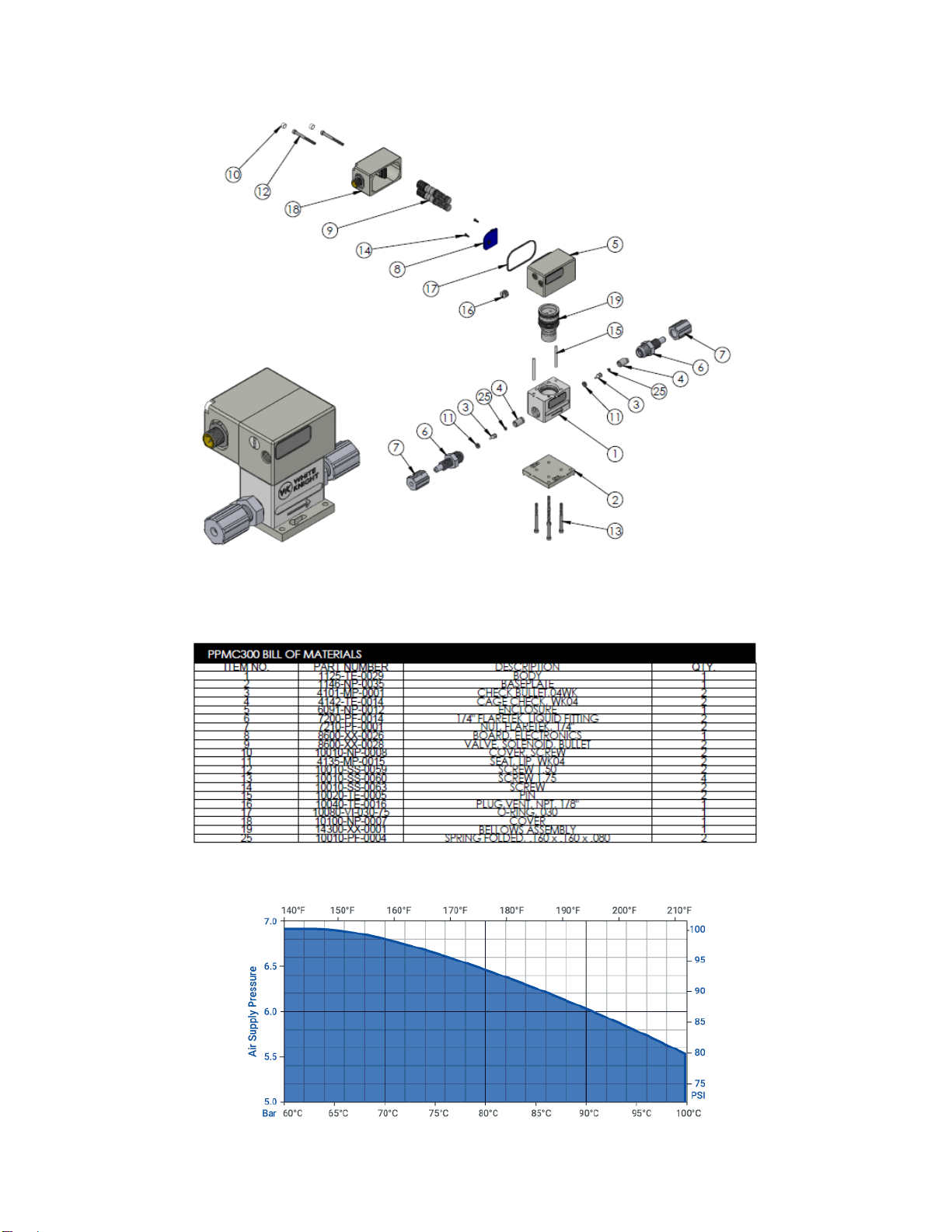
2.3 Exploded View............................................................................................................................................3
2.4 Temperature Limitations.............................................................................................................................3
3Pump Warranty....................................................................................................................................................4
4Installation and Precautions................................................................................................................................5
4.1 Precautions.................................................................................................................................................5
4.2 System and Pump Environment Recommendations/Requirements ..........................................................6
4.3 Installation Advantages...............................................................................................................................6
4.4 Installation Instructions...............................................................................................................................7
4.5 Connections................................................................................................................................................8
5Pump Control.......................................................................................................................................................9
5.1 Wire Connectors / Wire Leads....................................................................................................................9
5.2 Pump Operation..........................................................................................................................................9
5.2.1 Plug-n-Play .............................................................................................................................................9
5.2.2 External Control - Analog Input............................................................................................................ 10
5.2.3 External Control - Digital Input............................................................................................................. 11
5.3 Pump Orientation..................................................................................................................................... 11
5.4 Pump Dry Priming.................................................................................................................................... 11
5.5 Pumping for Accuracy.............................................................................................................................. 12
5.6 Flow Curves............................................................................................................................................. 12
6Pump Service & Rebuilds................................................................................................................................. 13
6.1 Ordering Instructions ............................................................................................................................... 13
6.2 Rebuild and Maintenance........................................................................................................................ 14
6.3 Rebuild Information.................................................................................................................................. 14
6.4 Return Pump to Factory........................................................................................................................... 14
6.5 Decontamination Instructions & Certificate of Decontamination ............................................................. 15

Manual Version 1.0.7 1
•••••••••••••••••••••••••••••••••••••••••••••••••••••••••••••••••••••••••••••••••••••••••••••••••••••••••••••••••••••••••••••••••••••••••••••••••••••••••••••••••••••••••••••••••••••••••••••••••
Copyright © 2022 White Knight Fluid Handling | A Graco company
1 Introduction
Thank You for Purchasing White Knight Products
You have purchased a White Knight product that has been designed to our exacting
specifications and built by a team of technicians with the highest commitment to quality!
White Knight is the world leader in zero-metal, ultra high-purity pumps and continues to drive
the industry with new technology and products. Since the inception of White Knight in 1995, we
have been awarded over 14 US patents for our designs and have multiple other patents
pending! White Knight currently produces over 30 sizes/models of pumps in varying materials
to meet our customers’ stringent requirements in numerous applications including ultra-high
temperature re-circulation, slurry and high-pressure chemical delivery systems.
White Knight has been the recipient of multiple prestigious industry awards for its designs and
continues to lead the industry in quality because White Knight manufactures products from raw
material to finished goods in our own facility located in Kamas, UT. This allows us to rigorously
manage our quality assurance process to ensure that our strict cleanliness procedures are
always followed and that components are built using consistent methods and conditions to
make our products reliable and consistent.
Our strict process controls include assembling and testing our products in a class 100,
temperature and humidity-controlled cleanroom. White Knight products also pass functional
tests and are then dried with CDA and double bagged in the cleanroom to ensure cleanliness
and operational integrity.
Before installing your White Knight product, please carefully review the product manual. There
are many helpful hints and ways to optimize the set up and use of your White Knight product
as well as instructions and requirements for installation. In addition, there are many
accessories in this manual that will enhance the functionality of your White Knight product.
Our team has gone to great lengths to provide you with the highest quality products at the best
value and we back them up with excellent warranties and world class support! We hope you
agree our products will serve your exacting needs and meet your stringent requirements every
time you use a White Knight Product.
Sincerely,
Brian Callahan, CEO
White Knight Fluid Handling

2 Manual Version 1.0.7
•••••••••••••••••••••••••••••••••••••••••••••••••••••••••••••••••••••••••••••••••••••••••••••••••••••••••••••••••••••••••••••••••••••••••••••••••••••••••••••••••••••••••••••••••••••••••••••••••
Copyright © 2022 White Knight Fluid Handling | A Graco company 6 October 2022
2 Specifications & Performance
2.1 Pump Specifications
PPMC300 Pump Specifications
Dispense
Volume
per Stroke1
Max Flow
Rate
Max
Discharge
Pressure
Max Air
Pressure
Max
Cycles
Per
Minute
Air
Consumption
SCFM
Fluid
Path
Materials
Fluid
Temperature
range
~0.75 ml
300
ml/min
11 Bar
(160PSI)
7 Bar
(100PSI)
400
~1 SCFM
PTFE
0-100°C
32-212°F
1. Stroke length varies depending on operation
Max Dry
Suction Lift1
Solenoid
Valves
Turck
Connector
On Board Controller
20 inches
2x
24V Manifold
Valves 0.7 CV
5 Pin O-ring
Sealed
Power: 24 VDC
Max Power Consumption: 6 Watts
Internal I/O:
•Two 24 VDC Valve outputs
External I/O:
•One 0-5 VDC analog input.
•Two NPN Compatible Signal Input
1. Dependent on CPM, requires min 200 CPM. Suction Lift degrades over time. Recommend install with
lowest possible suction requirement
2.2 Dimensions

Manual Version 1.0.7 3
•••••••••••••••••••••••••••••••••••••••••••••••••••••••••••••••••••••••••••••••••••••••••••••••••••••••••••••••••••••••••••••••••••••••••••••••••••••••••••••••••••••••••••••••••••••••••••••••••
Copyright © 2022 White Knight Fluid Handling | A Graco company
2.3 Exploded View
2.4 Temperature Limitations

4 Manual Version 1.0.7
•••••••••••••••••••••••••••••••••••••••••••••••••••••••••••••••••••••••••••••••••••••••••••••••••••••••••••••••••••••••••••••••••••••••••••••••••••••••••••••••••••••••••••••••••••••••••••••••••
Copyright © 2022 White Knight Fluid Handling | A Graco company 6 October 2022
3 Pump Warranty
White Knight Fluid Handling follows strict procedures in all phases of manufacturing, assembly,
and testing to ensure reliability of its products. Each pump is individually tested to assure its
functional operation integrity.
White Knight Fluid Handling warrants the PPMC300 pump, subassemblies and components to
be free from defects in materials and workmanship to 6 months from date of start-up, or 8
months from the date of shipment, whichever occurs first. Failures due to misuse, abuse or
any unauthorized disassembly of a White Knightpump will nullify this warranty.
The PPMC300 metering pump is warranted for up to 100 PSI air supply pressures, and 160
PSI discharge pressures. Wearable parts are not covered if used to pump abrasive slurries.
Due to the broad and ever-evolving applications for usage of White Knightpumps we cannot
guarantee the suitability of any pump component or subassembly for any particular or specific
application. White Knight Fluid Handling shall not be liable for any consequential damage or
expense arising from the use or misuse of its products in any application. Responsibility is
limited solely to the replacement or repair of defective White Knightpumps, components or
subassemblies. All options to rebuild or replace aforementioned items shall remain under the
judgment of White Knight Fluid Handling. Decisions as to the cause of failure shall be solely
determined by White Knight Fluid Handling.
Prior written, faxed or emailed approval must be obtained from White Knight Fluid Handling
before returning any pump component or subassembly for warranty consideration.
THE FOREGOING WARRANTY IS EXCLUSIVE AND IN LIEU OF ALL OTHER
WARRANTIES EXPRESSED OR IMPLIED INCLUDING ANY WARRANTIES OF
SUITABILITY FOR ANY PARTICULAR PURPOSE. NO VARIATIONS OF THIS WARRANTY
BY ANYONE OTHER THAN THE PRESIDENT OF WHITE KNIGHT FLUID HANDLING IN A
SELF-SIGNED AGREEMENT SHALL BE HONORED OR CONSIDERED LEGALLY BINDING.
Brian Callahan, CEO
White Knight Fluid Handling

Manual Version 1.0.7 5
•••••••••••••••••••••••••••••••••••••••••••••••••••••••••••••••••••••••••••••••••••••••••••••••••••••••••••••••••••••••••••••••••••••••••••••••••••••••••••••••••••••••••••••••••••••••••••••••••
Copyright © 2022 White Knight Fluid Handling | A Graco company
4 Installation and Precautions
4.1 Precautions
Use of Electronically Controlled Dispense Pumps
Electrically controlled dispense pumps do not qualify for use in explosion proof environments.
Handling
DO NOT LIFT PUMP BY LIQUID FITTINGS OR AIR TUBING!
Air Supply
The operation of the PPMC300 requires a minimum of 20PSI air supply pressure, ran through a minimum ⅛” ID
airline. Max air supply pressure is 100 psi. The pump operates with a pressure multiplier; discharge pressure can
exceed supply pressure (100PSI supply equals up to 160PSI discharge)
Dry Priming/Air Purging
For optimal performance of this pump the pump should be primed with liquid until no air is found in the
liquid dispense line. Mounting the pump in a vertical position, with the liquid inlet pointed down, and the
liquid outlet pointed up, is recommended.
Pumping Slurries and Abrasives
This pump is not recommended for pumping slurries or abrasives. Pumping abrasives will shorten the
life of the pump.
Restriction of Liquid Inlet Line
Restricting the liquid supply of the pump forces the pump to work harder than normal and should be
avoided when possible.
Cross Contamination
PTFE and many other plastics are very porous and may retain chemicals in the pores of the material. Record
chemistries used in a pump to avoid cross contamination.
WARNING: Liquids and Gasses Under Pressure
While in a live system, pumps contain pressurized liquids and gasses. All pressure,
liquid and air must be eliminated via shut off valves before the pump may be removed
or detached from the system.
WARNING: Handling of Chemicals
In the event that hazardous chemicals are used in or around the pump, ensure that
appropriate personal protective equipment is used before handling. Reference the
chemistry’s Material Safety Data Sheet (MSDS) for handling instructions or other
information specific to that chemical.
NEMA 5 Applications
The PPMC300 is capable of NEMA 5 classification. However, this requires that the end user route the vent air to a
safe location. The port is located on the front of the pump housing and is assembled and shipped with an orifice
plug to allow for immediate use upon arrival. The exhaust must remain clear of obstruction, or the motor housing
cover will disengage. The exhaust port is ⅛” NPT, recessed in the motor housing.
Liquid Fittings
The liquid fittings on this pump use tongue and groove seals and contain check valves. Over-torque of the fittings
will damage the threads and reduce the performance. Because of this, the fittings are pinned in place. Rotation
after initial assembly will damage the fittings. Always use a backer wrench when applying torque to fittings.
Do not Disassemble These Fittings Without Prior Training From White Knight.

6 Manual Version 1.0.7
•••••••••••••••••••••••••••••••••••••••••••••••••••••••••••••••••••••••••••••••••••••••••••••••••••••••••••••••••••••••••••••••••••••••••••••••••••••••••••••••••••••••••••••••••••••••••••••••••
Copyright © 2022 White Knight Fluid Handling | A Graco company 6 October 2022
4.2 System and Pump Environment Recommendations/Requirements
4.3 Installation Advantages
Clean Supply Air (CDA)
White Knight high purity pumps require the use of Class 2 air for particles and moisture per ISO 8573-1. (Use 10-
micron filter, maintain -40° C dew point)
Environmental Temperature
This pump is rated to withstand environmental temperatures up to 80°C.
High Discharge Pressure
The PPMC300 is capable of discharging at pressures up to 160 psi. Max air supply is 100 psi.
Mounting Orientation
The PPMC300 can be mounted in any orientation. For optimal air purge, resulting in highest repeatability, the
pump should be mounted such that the fluid flows vertically.

Manual Version 1.0.7 7
•••••••••••••••••••••••••••••••••••••••••••••••••••••••••••••••••••••••••••••••••••••••••••••••••••••••••••••••••••••••••••••••••••••••••••••••••••••••••••••••••••••••••••••••••••••••••••••••••
Copyright © 2022 White Knight Fluid Handling | A Graco company
4.4 Installation Instructions
Decide where the pump is to be mounted. For
optimal performance mount the pump such that
the fluid path flows uphill (with air and power
connections pointing down as shown in the
Images to the right).
Drill and tap 3 #6-32 holes using the baseplate
dimensional for positioning the holes.
Insert #6-32 socket head cap screws into location
for the key slot holes. Leave enough room for
base plate to slide under screw cap; about ¼”.
Slide pump into position using the key slot hole to
help hold pump in place.
Insert and tighten the remaining 2 #6-32 socket
head cap screws into position on opposite side of
pump.
Tighten the key slot screws.
The pump is now secured.
Attach liquid fittings inlet on the side with the air
and electrical connections, and the outlet on the
opposite side. Use a backer wrench so that the
fitting is not damaged.
Attach electrical connector to the M12 Turck male
receptacle.
Attach air pressure to the CDA inlet port using 1/8”
FNPT port.

8 Manual Version 1.0.7
•••••••••••••••••••••••••••••••••••••••••••••••••••••••••••••••••••••••••••••••••••••••••••••••••••••••••••••••••••••••••••••••••••••••••••••••••••••••••••••••••••••••••••••••••••••••••••••••••
Copyright © 2022 White Knight Fluid Handling | A Graco company 6 October 2022
4.5 Connections
The pump has 5 connections:
•Fluid Inlet Port: This port is to be connected to the fluid reservoir that is to be pumped. Standard Flaretek
and Pillar compatible options available. See ordering instructions.
•Fluid Outlet Port: This is the pump outlet and should be connected to where the pump is to pump the
fluid. Standard Flaretek and Pillar compatible options available. See ordering instructions.
•Exhaust Air Port: This port is to vent the exhaust air from the pumping operation. An orifice NPT plug is
connected to this port by default. If the user wants this air to exhaust to a remote location then the orifice
plug can be removed and connected to a tube via the 1/8” FNPT port. Do not plug this port.
•CDA Input: This port is to supply the CDA input pressure. The pump will use this air pressure to
pressurize the discharge liquid. The discharge liquid pressure will be 6 times the CDA input pressure. Air
fitting is a 1/8” FNPT port.
•Power & I/O Port: This is the electrical power port that supplies power to the on-board controller and to
the I/O. More information on the pin out and controls is found in section 6. Connection type male M12 5-
pin receptacle made by TURCK.
Exhaust Air Port
Power & I/O Connection:
Fluid Inlet Port
Fluid Outlet Port
CDA Input:
1/8in FNPT

Manual Version 1.0.7 9
•••••••••••••••••••••••••••••••••••••••••••••••••••••••••••••••••••••••••••••••••••••••••••••••••••••••••••••••••••••••••••••••••••••••••••••••••••••••••••••••••••••••••••••••••••••••••••••••••
Copyright © 2022 White Knight Fluid Handling | A Graco company
5 Pump Control
5.1 Wire Connectors / Wire Leads
The PPMC300 has Turck EuroFast male receptacle coming out of the front of the device. This connector both
powers the on board controls and provides external I/O for the device. A mating cable is available and wire colors
shown in the diagram relate to the optional cable.
Turck Pin/
Wire Color
Function
Connection Type
Connector Diagram
1 / Brown
Power
24 VDC Power Supply
2 / White
Analog Input
0-5 VDC Analog Input to set Cycle Rate.
- 0-1 VDC = Pump Off
- 1-5 VDC = Pump On = 0-400 CPM
3 / Blue
Common Ground
0 VDC Ground, Analog Reference
4 / Black
Valve Control
Actuate Pump Suction
Sink Type Signal
- 24 VDC = Not Active
- 0 VDC = Active
5 / Gray
Valve Control
Actuate Pump Discharge
Sink Type Signal
- 24 VDC = Not Active
- 0 VDC = Active
5.2 Pump Operation
There are several modes which the pump can operate.
•Plug-n-Play –This is a constant run mode, meaning that when the pump is powered on it will operate
without any additional signals. This option can be ordered in one of two ways:
oUser Configurable –This means that the internal potentiometer will be preset to the specified
cycle rate so that the pump will run when powered on in the initial set up of the pump by the
customer. However, the user has the ability to tweak the cycle rate by adjusting the internal
potentiometer.
oHard Coded –This means that the processor will be preprogrammed at the factory to operate at
the specified cycle rate only and is not adjustable by the end user.
•External Control –This is an idle operation and does not start-up when powered on. When the pump is
powered on then it watches for external control signals to define its operation. The external controls can
be given in the following ways:
oAnalog Input –This external control uses a 0-5 VDC analog signal to define the cycle rate. The
analog signal can change the operation signal from 10 to 400 CPM.
oDigital inputs –This external control allows an external PLC to directly control the timing of the
pump’s air valves, thus controlling the pump’s cycle rate.
oFree Flow –In some cases it is advantageous to know that when the pump is idle, that there is
still a forward path that is free to flow. This can help in pump priming, and in decontamination. A
positively pressured supply line will open the checks and allow fluid to flow though the pump.
The following sections will go into more detail about how each of these control modes work.
5.2.1 Plug-n-Play
Working with Plug-n-Play is very easy, power the pump when you want it to pump, and remove power from the
pump when you don’t want the pump to operate. The cycle rate is based off of either the factory programmed

10 Manual Version 1.0.7
•••••••••••••••••••••••••••••••••••••••••••••••••••••••••••••••••••••••••••••••••••••••••••••••••••••••••••••••••••••••••••••••••••••••••••••••••••••••••••••••••••••••••••••••••••••••••••••••••
Copyright © 2022 White Knight Fluid Handling | A Graco company 6 October 2022
cycle rate (which needs to be specified at the time of purchase), or from the internal potentiometer that can be
accessed from inside the electrical enclosure (see below in section 5.2.1.1.). A device that was not previously set
in Plug-n-Play operation can be modified to operate to perform in this manner, and if a pump was set in plug-n-
play, and was not hard coded, can be modified to accept external controls.
5.2.1.1 Switching Between Plug-n-Play and External Control:
To switch the operation mode of
the PPMC300, the electrical cover
will need to be removed. To
remove the cover, remove the
cap screw covers and the two cap
screws that hold the electrical
cover in place (shown in image to
the left). Once the cover has been
removed find the surface mount
potentiometer on the circuit board
(Shown in image to the right). Use
a small flathead screwdriver and rotate the potentiometer to the desired position. Rotating clockwise will decrease
the cycle rate, and rotating counter-clockwise will increase the cycle rate.
Note: there are no hard limits. After reaching minimum and maximum cycle rates the potentiometer will continue
to rotate without changing value. Full range of the cycle rate requires multiple turns to achieve.
Note: the potentiometer can be adjusted while the power is on, to assist in properly tuning the cycle rate.
However, care should be taken to not short circuit the circuitry.
Note: A revision change in 2022 inverted the rotation direction of the potentiometer to increase and decrease
cycle rate. If the desired effect is not achieved, attempt to rotate in the opposite direction.
After the potentiometer is set in either the Plug-n-Play operation, or in External Control operation the electrical
cover should be replaced being careful to not pinch any wires. Tighten the socket head screw caps until they are
snug; do not over tighten, as this could strip out the plastic housing. Replace the screw cap covers.
5.2.2 External Control - Analog Input
With the Plug-n-Play control disabled, then the pump is in external control. At this point the imbedded controller
watches its analog input and will vary its cycle rate depending on the signal received. Analog input signal is 0-5
VDC with the common ground from the power input is the reference voltage for the analog input signal. The
analog input is interpreted as follows:
•0-1 VDC: Pump will not operate.
•1 VDC: is the transition from on to off, and should be avoided as a signal input, as the pump may toggle
between the on and off position and will not flow.
•1-5 VDC: Pump will operate based upon the voltage to cycle rate conversion equation below.
o𝐶𝑦𝑐𝑙𝑒𝑅𝑎𝑡𝑒 = 100 ∗ 𝑉𝑜𝑙𝑡𝑎𝑔𝑒𝐼𝑛𝑝𝑢𝑡 − 100
oThis equation outputs a linear cycle rate output below are some example voltage to cycle rates:
▪1.1 VDC = 10 CPM
▪2 VDC = 100 CPM
▪3 VDC = 200 CPM
▪4 VDC = 300 CPM
▪5 VDC = 400 CPM

Manual Version 1.0.7 11
•••••••••••••••••••••••••••••••••••••••••••••••••••••••••••••••••••••••••••••••••••••••••••••••••••••••••••••••••••••••••••••••••••••••••••••••••••••••••••••••••••••••••••••••••••••••••••••••••
Copyright © 2022 White Knight Fluid Handling | A Graco company
5.2.3 External Control - Digital Input
With the Plug-n-Play disabled, the pump requires external control signals. In digital input control method, the user
has the most flexibility in operating the pump. The user specifies a faster and slower cycle rate by directly
controlling the timing of the valves. There are two digital inputs that connect to the internal air valves. One is tied
to the pistons’ up stroke and the other is tied to the down stroke. The pump works by oscillating the up stroke and
the down stroke signals opposite of each other. The digital signals work with NPN or Sink type digital connections.
An example digital control signal is shown below:
Note: The CPT-1 is a pump controller offered by White Knight and is capable of operating the PPMC300 in digital
control mode.
5.3 Pump Orientation
This pump uses spring loaded checks which enables the pump to
be oriented in any direction. This provides design flexibility allowing
it to be mounted anywhere. While the pump can be mounted in any
direction and function, there is still a preferred mounting
orientation. This pump prefers to be mounted such that the flow
path travels up hill; this allows for air bubbles that might travel in
the line to have a free path to exit the pump and be more
repeatable.
5.4 Pump Dry Priming
Because of the small size of this pump, it has a limited dry prime
capability of approximately 20”. Dry prime functions optimally
between 200-400 CPM, and with 80 PSI air pressure. Once the
pump is primed then much higher suction lift is available.
For applications that require higher suction lift a DI water purge can be used to prime the pump. To perform a DI
water purge, connect a pressurized DI line to the pump inlet, let the water run till you see fluid coming out the
outlet, then switch back to the source tank. This can be done by placing a 3-way valve on the inlet line; then the
user could switch between the DI water and the supply tank.
Flow Direction

12 Manual Version 1.0.7
•••••••••••••••••••••••••••••••••••••••••••••••••••••••••••••••••••••••••••••••••••••••••••••••••••••••••••••••••••••••••••••••••••••••••••••••••••••••••••••••••••••••••••••••••••••••••••••••••
Copyright © 2022 White Knight Fluid Handling | A Graco company 6 October 2022
5.5 Pumping for Accuracy
This pump is designed as a device that creates backpressure to move chemistry from one location to another.
Some customers may want to use this device for dosing or for more precision pumping applications. In order to
achieve the higher accuracy required for pumping for dosing type applications it is recommended to pump though
an orifice or into a line with some back pressure. Adding back pressure on the pump’s outlet makes the pump
perform more repeatable and reduces wear on the checks, which will give a more constant performance over the
life of the pump. When the outlet is restricted, then the flow will be analogous to a pressurized line flowing through
a known orifice, resulting in a more stable flow.
5.6 Flow Curves
*300 mL/min at wide open flow path. The Flow Chart measurements shown are using a back-pressure
regulator to simulate a pressurized system; results may vary.

Manual Version 1.0.7 13
•••••••••••••••••••••••••••••••••••••••••••••••••••••••••••••••••••••••••••••••••••••••••••••••••••••••••••••••••••••••••••••••••••••••••••••••••••••••••••••••••••••••••••••••••••••••••••••••••
Copyright © 2022 White Knight Fluid Handling | A Graco company
6 Pump Service & Rebuilds
6.1 Ordering Instructions
Wkfluidhandling.com/ordering-instructions
Please contact White Knight for orders requiring Copy Exact.

14 Manual Version 1.0.7
•••••••••••••••••••••••••••••••••••••••••••••••••••••••••••••••••••••••••••••••••••••••••••••••••••••••••••••••••••••••••••••••••••••••••••••••••••••••••••••••••••••••••••••••••••••••••••••••••
Copyright © 2022 White Knight Fluid Handling | A Graco company 6 October 2022
6.2 Rebuild and Maintenance
Rebuild Parts for PPMC300 Pump
Part Number Description Quantity
8600-XX-0028 Solenoid Valves 2
14300-XX-0001 Bellows Assembly 1
7200-PF-001411/4in Flaretek Comp. Liquid Connection 2
10010-PF-0003 Check Spring 2
4135-MP-0012 Check Seat 1
4101-TE-0001 Disk Check 2
10080-VI-030-75 O-Ring 1
8600-XX-0026 Controller 1
10020-TE-0005 Pin 2
1. Part referenced is the check cage, as well as the liquid connection for 1/4in flaretek compatible fittings. For alternate liquid connections,
contact White Knight at customer.support@wkfluidhandling.com.
6.3 Rebuild Information
Pumps requiring service under warranty must be returned to White Knight for warranty coverage. Options for out-
of-warranty pumps are listed below in order of recommendation.
1. Return the pump to White Knight for a full evaluation, failure analysis, and quote issued by White Knight or our
local distributor. Upon the acceptance of the quote in the form of a purchase order the pump will be rebuilt as
outlined in the quote. Pumps that undergo a full rebuild will be returned with a full renewal of its original warranty.
6.4 Return Pump to Factory
1. After removing the pump from the station, the pump must be flushed as described in the “Attention”
section of this document, decontamination instructions and certificate of decontamination in section 6.4.
2. Remaining DI water in the pump should be drained from the inlet and outlet liquid tubing connectors.
3. The pump liquid outlets must then be plugged per manufactures instructions
4. Dry the pump.
5. Double-bag the pump - sealing it in thick polyethylene bags.
6. Return the pump to its original packaging.
7. Include Material Safety Data Sheet (hereafter MSDS) in the box with the pump for any chemical to which
the pump was exposed.
8. Obtain RMA number from White Knight, and write it on the outside of the box.
(https://wkfluidhandling.com/support/rma/)
9. Ship to White Knight following all rules, regulations and laws regarding the shipping of dangerous
materials. Ship freight pre-paid. No collect or COO shipments will be accepted. Unauthorized use of
White Knight shipping accounts will result in additional freight costs to the bill as well as a service
charge. Follow all shipping instructions in reference to sending your pump to its appropriate suite.
Location of Rebuild Site
Due to the nature of the PPMC300 metering pumps, rebuilds of the PPMC must be performed at White
Knights facility. White Knight reserves the right to refuse a rebuild request.

Manual Version 1.0.7 15
•••••••••••••••••••••••••••••••••••••••••••••••••••••••••••••••••••••••••••••••••••••••••••••••••••••••••••••••••••••••••••••••••••••••••••••••••••••••••••••••••••••••••••••••••••••••••••••••••
Copyright © 2022 White Knight Fluid Handling | A Graco company
6.5 Decontamination Instructions & Certificate of Decontamination
Attention:
White Knight products are designed for use with caustic and otherwise dangerous liquids. Therefore,
every product must be handled as if it contains dangerous chemicals. White Knight specifies that if a pump
runs under its own power, the pump should circulate DI water for twenty minutes before disassembly or
double-bagging for shipment. If the pump does not run under its own power, then DI water should be forced
from the inlet, through the outlet for 40 minutes before disassembly or double-bagging for shipment. Only
those who have been adequately trained in safety with the handling of acids and other dangerous chemicals
should attempt to handle a White Knight pump that has been exposed to dangerous chemicals. Adequate
safety gear appropriate for the chemical that has been in the pump must be used and no attempt should be
made to handle the pump until MSDS for the chemical that the pump has been used in have been reviewed.
Ph papers, showers, antidotes, clean-up equipment, neutralizers, and any other safety devices that could be
used for detecting, neutralizing or minimizing effects from the chemical described in the appropriate MSDS
must be present along with emergency numbers for use in the event of an accident. Take care in the
handling of liquids and/or residues contained in these pumps or any other chemical handling equipment.
Remember, Safety First.
Note:
Any pumps returned to White Knight for warranty evaluation or repair must be complete with all
parts and components including but not limited to tubing connectors, tubing connector caps, flare
noses and tubing. Any missing parts will be added to the pump and charged to the customer in the
event of repair or replacement, warranty or otherwise.
Return Material Authorization requests may be filed online here:
https://wkfluidhandling.com/support/rma/
Removal of Pump from Station:
1. Disconnect air supply from the pump.
2. Disconnect liquid lines.
3. Plug liquid fittings per manufactures instructions or plug the pump inlet/outlet ports with a
White Knight buttress plug.
4. Remove the pump from its base plate.
5. Return all removed parts with the pump.

Manual Version 1.0.7 Manual Part Number: 18200-LM-0066

Manual Version 1.0.7

Manual Version 1.0.
Table of contents
Other White Knight Water Pump manuals

White Knight
White Knight PSD06 User manual

White Knight
White Knight PSD04 User manual

White Knight
White Knight PEM050 User manual

White Knight
White Knight PSD16 User manual

White Knight
White Knight PSD24 User manual

White Knight
White Knight PSA140SS User manual

White Knight
White Knight PSD08 User manual

White Knight
White Knight AT100 User manual
Popular Water Pump manuals by other brands

TAEHA
TAEHA PDP-1000 user manual

PYD Electrobombas
PYD Electrobombas PC 32 8 220 instruction manual

LEYBOLD
LEYBOLD VARODRY VD65 operating instructions

T.I.P.
T.I.P. WPF 1500 S operating instructions

GORMAN-RUPP PUMPS
GORMAN-RUPP PUMPS D Series Installation, operation, and maintenance manual with parts list

Hydor
Hydor Koralia 900/240 user guide