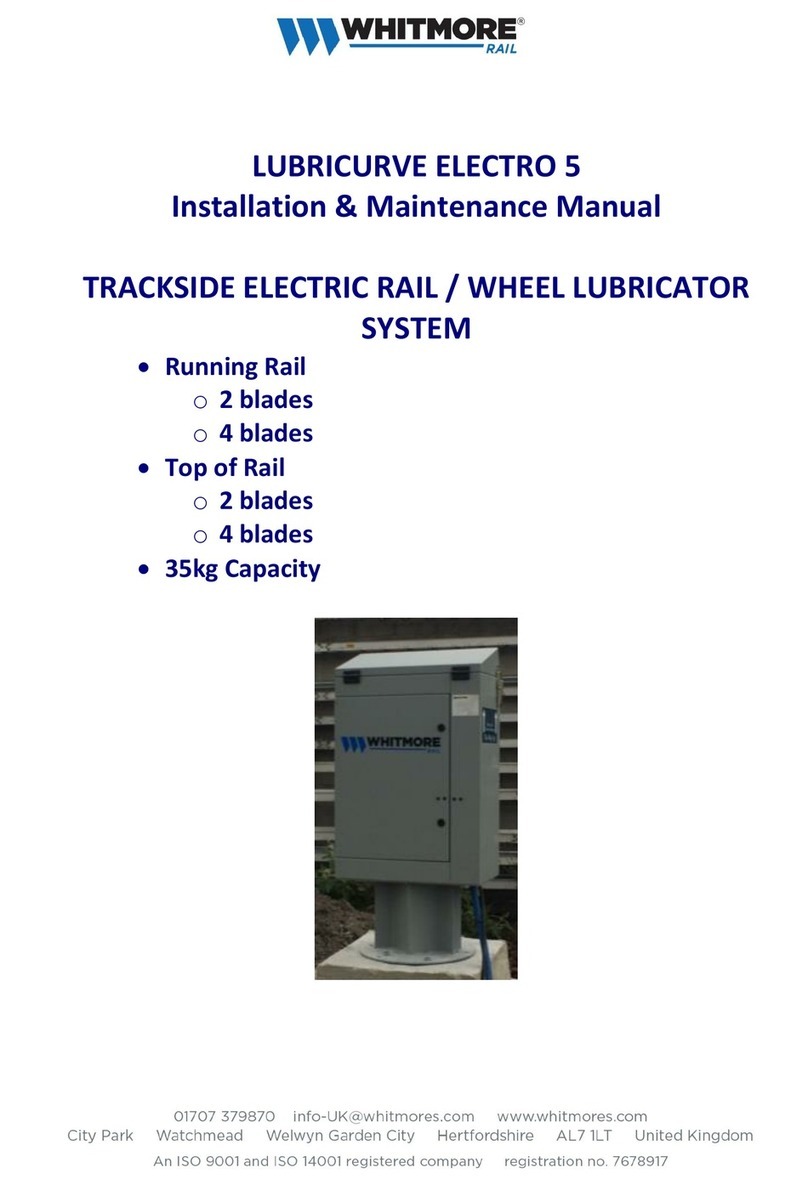
Whitmore LUBRICURVE ELECTRO 10 Instruction Manual

LUBRICURVE ELECTRO 10, 20, 30
Installation & Maintenance Manual
TRACKSIDE ELECTRIC RAIL & WHEEL LUBRICATOR
SYSTEM
Model Variants:
Solar (Mast) • Solar (Cabinet)
Solar & Wind • Mains
Battery • Control box MK3
90Kg, 200Kg, 400kg Capacity

2
Warning!
This lubricator uses a 12V-100Ah battery which contains a dilute sulfuric acid solution
known as electrolyte. Care must be taken to avoid the electrolyte coming in contact
with the skin or clothing as the electrolyte may cause severe burns.
If the electrolyte contacts the skin, wash with large quantities of clean water and seek
medical advice.
DO NOT expose the battery to naked flames or cigarettes
During the charging process hydrogen gasses are vented from the battery and these
gasses when mixed with the air may explode if ignited.
Do not short circuit the battery terminals, as this may cause a spark or explosion.

3
.Contents
1General 5
2Product Transport / Storage 5
3Main Component Definitions 6
4Preparation of Main Components for Installation 7
5Equipment Handling 8
6Typical Install Process 8
7Site Preparation 9
8Installation Trackside Items 12
8.1 Fitting the Trackside Cabinet to Mounting Base 12
8.2 Cabinet Door 13
8.3 Earth Bond 13
8.4 Lowering the Integral Lower Mast Unit 14
8.5 Option –Mast Removal / Alternative Lower Mast Orientation 14
8.6 Fitting the Upper Mast (wind turbine and / or solar power option) 15
8.7 Fitting the Solar Panel 15
8.8 Fitting the Wind Turbine 16
8.9 Raising the Integral Mast 17
8.10 Optional Mast Extension 18
8.11 Fitting of Cabinet Mounted Solar Panels 19
8.12 Battery Charger Electrical Connection 19
8.13 Solar & Wind Systems 20
8.14 Solar Systems - Mast Mounted 21
8.15 Solar Systems –Cabinet Mounted Panels 21
8.16 Mains Powered Systems 22
8.17 Battery Powered Systems 24
8.18 Replacing the Pump Sensor 24
9System Wiring Diagram 25
10 Installation of Track Items 26
10.1 Wheel sensor 26
10.2 Wheel sensor –Single Direction Operation 27
10.3 Blade System 29
10.4 Installing the Blade Rail Clamps (Standard Style) 29
10.5 Installing the Blades (Standard Style) 29
10.6 EasiBlade Installation 30
10.7 Outing of delivery hoses, Cabinet to blade 31
10.8 Fitting the Main Delivery Hoses 32
10.9 Fill the Hoses and Blade’s 33
11 Commissioning / Setting 34
11.1 Filling the Reservoir (Lid Lift Version) 34
11.2 Wheel sensor Heights and Operation 35
11.3 Pump Setting 35
11.4 Backlight & voltage display feature panel Error! Bookmark not defined.
11.5 Non backlight panel Error! Bookmark not defined.
11.6 Pump Settings / Operation 40
12 Routine Maintenance 41
12.1 Control Panel 41
12.2 Pump Setting 41
4
12.3 Measuring the Reservoir 42
12.4 Cabinet Maintenance 42
12.5 Battery Maintenance 42
12.6 Solar Panel Maintenance 43
12.7 Cleaning the Lubricator and Surrounding Site 43
12.8 Checking for Leaks 43
12.9 Measuring / Testing the Wheel sensor 44
12.10 Adjusting / Replacing Pump Sensor 44
12.11 Checking for Airlocks 45
12.12 Inspection of the Blade’s 45
12.13 Filling the Reservoir 46
12.14 Maintenance Frequency 46
12.15 Periodic Replacement of Components 46
12.16 Maintenance Log Sheet Example 47
13 Parts List 48
14 Basic Installation Tool Kit 48

5
1 General
Health & Safety legislation requires that rail lubricators are fitted by trained personnel only; warranty
will also be affected if un-trained teams work on the LubriCurve products.
Whitmore Rail provides suitable training courses.
This Manual should be used in support of training courses.
This Instruction Manual is intended to be generic and concentrates on the full range of LubriCurve
Electro 10/20/30 systems to suit flat bottom running rails; system install differences are highlighted
as necessary.
The lubricator uses a 12 Volt 115 Ah battery as a power source.
Only lubricator greases approved for use by Whitmore Rail and the rail user can be used in these
LubriCurve Electro systems. Use of other greases will invalidate warranty and could affect operation.
2 Product Transport / Storage
Goods are packed and delivered to the requested address in a form that is suitable for the product,
given good practice in the off-loading by the receiving company.
LubriCurve systems are delivered on the basis that they will be installed within one month of receipt.
Delivered systems are not intended for outside storage, equipment should be off loaded and stored
inside a secure watertight building until required for installation.
All items are carefully checked prior to despatch and any damage or missing parts should be advised
to Whitmore Rail within five days of despatch from Whitmore Rail premises.
Note:
Keep the cabinet upright at all times from transport to install

6
3 Main Component Definitions
Pump
Cabinet
Each trackside Cabinet contains: Reservoir, gear pump, gear pump hose, flow
adjusters, control panel, battery charger, reservoir filling valve, Cabinet mounting
brackets (fixed to the Cabinet).
The grease is delivered from the reservoir via the gear pump to the bulkhead hose
connectors on the external face of the Cabinet. Feed hoses then transfer grease to
the Blade system.
Pump
Reservoir
This reservoir holds the rail grease. The LubriCurve Electro 10 reservoir is capable of
holding 90Kg of grease, the Electro 20 –200kg and Electro 30 –400kg.
Pump
The pump unit consists of a twin chamber gear pump driven by a close-coupled 12v
DC motor. The unit fits directly to the reservoir underside.
Pump
Control
Triggered from the Wheel sensor the unit allows control of the pump and recording of
key data. A number of operational settings are user adjustable to suit the site and
application.
Wheel
Sensor
The wheel sensor clamps to the running rail and provides non-contact sensing of
passing wheels. Indicating lamps provide local indication of correct operation during
test. Sensor is connected to control box through armoured cable.
Integral
Mast
Generally integral with the Cabinet, the mast provides secure mounting of the solar
panel or wind turbine at a high level. Various heights and options are available.
Solar Panel
Depending on the model a solar panel is supplied. The unit fits onto the mast and is
used to provide power to the battery by utilising sun light and ambient light to
generate electric power.
Wind
Turbine
Depending on the model supplied a wind charger is supplied. The unit fits into the top
of the mast and is used to provide power to the battery in conjunction with the solar
panel.
Delivery
Hose
The delivery hose transfers the grease from the pump outlet to the Blade inlet.
Lengths of hose are supplied with each lubricator, which have to be cut into suitable
lengths to fit between the trackside Cabinet and Blade assemblies.
The hose is secured using a hose clip at each end of the hose.
Blade
(Grease
Dispensing
Unit - GDU)
Blades are provided which allows the grease to be delivered to the gauge corner
and/or gauge face of the rail for the train wheels to pick up and spread along the
curve. The quantity supplied is dependent on the application specified.
Each consists of three rectangular plates, back plate, middle plate and grooved front
plate (which has eight ports at the top of the grooved plate). Each Blade rail clamps
are suitable for the blade type.

7
4 Preparation of Main Components for Installation
Application
Ensure the correct pump type and system options have been selected for the
application.
Training
Ensure the installation team has been fully trained on the product, siting and
the application.
Packing
The Cabinet is delivered pallet mounted and wrapped, the Cabinet contains
the majority of loose items required for the install, and larger items are
secured to a separate pallet and wrapped.
Ensure the package has not been damaged during storage or transport to rail
site, damage must be reported to the equipment supplier on initial receipt.
Dispose of all waste packaging materials responsibly.
Cabinet
Visually inspect for any defects that will affect its operation.
Ensure that all loose items are available with reference to items ordered.
Ensure that the battery is fully charged with reference to the green indicator
lamp on the charge controller or the voltmeter display.
Blade
Ensure the blades are not bent or damaged and all ports are free from
blockages.
Ensure that all bolts are present and are fitted securely.
Ensure that the hose inlet tails, which the delivery hoses attach to, are in place
and are not damaged.
Clamps
Ensure that both Sensor and Blade clamps are not damaged.
Ensure that the threads on the clamp studs are not damaged.
Ensure that the threads on the hook bolts are not damaged.
Hoses (feed and
delivery)
Ensure that the hoses are intact and free of holes and splits.
Wheel sensor & Cable
Ensure that the cable and sensor are intact and free of sharp kinks and any
kind of damage.
Serial Numbers
Lubricators are supplied with unique serial numbers; these should be recorded
prior to installation and recorded on installation record sheets as required.
Serial numbers are on both external and internal faces of the cabinet (door
hinge side)
Note:
Keep the cabinet upright at all times from transport to install

8
5 Equipment Handling
Generally Electro 10/20/30 items required for each site are delivered within the cabinet or attached
to it. The lubrication system is heavy and care should be taken in general, ensure safe mechanical
handling of the units from delivery truck off-load to site install (cabinet weight excluding grease is
over 100kg). There are three appropriate methods of handling the unit:
Fork Lift Truck. Lift with forks fully engaged under the cabinet.
Sling / Crane. The unit is designed to be lifted from the mast by attaching a suitable sling
around the ‘H’ frame. However the M12 fixings must be fitted through the mast
base plate to securely clamp the mast base to the cabinet prior to lift.
Personnel There are four carry points on the unit to suit the Whitmore Rail carry kit (Part
No. LCS105-01) and these should be used for all cabinet movements. The handle
should be passed through the corner angle-fixing hole and rotated vertically
through 90 degrees to secure. Four people are required, which should be trained
and experienced in mechanical handling. To reduce the overall weight, the
battery and other loose installation items that are shipped within the unit, should
be carefully removed prior to the lift and handled separately.
Note
The cabinet should be kept vertical at all times,
Take care to avoid damage to the paint finish as this forms part of the corrosion
resistance and general integrity of the unit.
6 Typical Install Process
There are several possible sequences that can be followed to efficiently install the lubricator, this will
largely depend on the personnel available, track access and general conditions –the following is
recommended as a guide.
Activity
Manual Section
1. Equipment Handling
5
2. Prepare Base for Cabinet Install
7, 8.1
3. Connecting the Power Source (solar, solar & wind, mains, battery)
8.4
4. Electrical Connection
8.12, 10.1
5. Install Blades
10.3
6. Install Track Mounted Wheel Sensor
10.1
7. Hose connection and routing from Blades to Cabinet
10.8
8. System Priming
10.9
9. System Settings
11

9
7 Site Preparation
To install a LubriCurve Electro 10/20/30 lubricator, a simple base is required to mount the Cabinet. The
form and stability of the base is important as it resists the wind loads on the solar panel and / or wind
charger. Typically the base would be formed from a pair of wood Sleepers / Ties suitably bedded into
ballast or surrounding ground. Alternatively a concrete plinth can be formed but that can be a costly
solution.
Systems with Masts
Outline and requirements are indicated in the diagram below. Recommendation is for two full length
(8’ 6”) good quality hardwood Sleepers / Ties to be fitted at 900to the track.
Where there is insufficient space in the CESS for that arrangement then two alternative options are
possible:
oTwo ¾ length (6’) sleepers can be used in place of the 8’ 6” standard, sleepers at 900to
the track. Sleepers must be ballast covered for adequate stability.
oTwo full length (8’ 6”) sleepers can be used. The sleepers must be parallel to the track and
spaced 0.95 metres (37”) apart. Sleepers must be ballast covered for adequate stability.
For any orientation described, sleepers are to be horizontal and level relative to each other and fully
bedded into ballast or secure ground.

10
The drawings below are applicable to the Electro 10 and Electro 20 systems.
640 nom'
1240
460
460 150 460
700 nom'
800 nom'
500 nom'
Direction of
Train Travel
View on arrow A
A
2897 3810
2150
2000
2100
2438 (8') nominal

11
Alternative Mounting Base
Standard sleeper
Dug in parallel to
the track
Short Sleeper
Dug in at 900to the
track
2100
2000
1829 (6') nominal
950 overall
700 nom'
centres
460 460
800 nom'
640 nom'
500 nom'
Direction of
Train Travel
950,0
2100
2000
950 overall
700 nom'
centres
460 460
800 nom'
640 nom'
500 nom'
Direction of
Train Travel

12
Systems without Masts
Applies to mains power units and cabinets with integral solar panels on two sides
Wind loadings are much lower with these power configurations.
Recommendation is for sleeper base as described above for cabinets with masts. However the use of
6’ (1.8metre) wood sleepers is acceptable with the orientation either parallel or at 90oto the track.
General
The base and cabinet must be positioned to maintain the mandatory track and OLE clearances.
Vegetation should be cleared around the unit where necessary to ensure a safe working
environment.
The base should be securely bedded into the ground / ballast to ensure stability, sleepers should be
levelled in both planes (horizontal and vertical).
As soon as the cabinet is manoeuvred onto the base it should be securely bolted down (see Section
8.1).
The equipment required for the installation work includes the following:
oAll relevant P.P.E. needed to carry out the works safely.
oShovel or ballast fork whichever one is the most suitable.
oOrange pipe to protect delivery hose and sensor cable across 4’ and 6‘.
oSpirit level.
oCompass.
oLubricator installation tool kit (see Section 14).
oWiring termination tools.
oCordless or portable drill and bits.
8 Installation Trackside Items
8.1 Fitting the Trackside Cabinet to Mounting Base
8.1.1 The sleeper or plinth base must have been fully
installed before commencing any installation of
the unit. Recommended platform / sleeper
install dimensions are shown in Section 7.
8.1.2 The Cabinet includes two robust angle sections
at the base of the unit with a pair of mounting
holes at each end. Locate the unit in the
required position ensuring that at least four
holes (one of each hole pair) can be used.
8.1.3 Suitable fixings are available from Whitmore
Rail to suit wood or concrete bases. Part
Numbers LCS105-07 and LCS105-08
respectively.

13
8.1.4 Drill the base using the Cabinet fixing holes as guides; wood fixings require an 8mm
diameter pilot hole, while concrete requires a 12mm diameter hole. Insert fixings and
tighten securely. One fixing in each corner of the cabinet is required using either inner or
outer holes as appropriate.
8.2 Cabinet Door
8.2.1 There are two options of door locks. The early units are
supplied with one set of door locks, consisting of one
security key and a hexagon tool to activate the three-
point door lock. To open the door the key should be
inserted and rotated clockwise (the key will now be
captive in the lock). Insert the Hexagon tool, press
inwards and rotate clockwise. The door can now be
opened.
8.2.2 The later units have a single key door lock. To open the
door the key is inserted into the lock, located behind the
vertically sliding dirt shield. Rotate the key clockwise and
pull the key and handle outwards. The handle can now be
rotated clockwise to open the three point locking bars
and then open the door.
8.2.3 The door stay at the base of the door should be located in
the frame locator hole to prevent accidental door and
hinge damage by over travel.
8.2.4 Closing is the reverse procedure.
8.3 Earth Bond
8.3.1 Subject to local regulation it may be required to bond the unit to the track. At the rear of
the unit a mounting hole is available for a 16mm diameter earth stud (Whitmore Rail part
No. LCS105-11).
8.3.2 The bond itself must be supplied and fitted directly by the Rail owner authorised personnel
and not by the lubricator installer.

14
8.4 Lowering the Integral Lower Mast Unit
8.4.1 Solar and Solar / Wind powered models are
supplied with the Lower Mast fitted vertically
and held in place by two U bolts on each side
of the cabinet. The mast needs to be rotated
horizontally to ground level to attach the
solar panel and/or wind turbine.
8.4.2 Remove the U bolts located toward the top
of the Cabinet by removing the four M10
Nyloc nuts on the inside of the cabinet, (a
17mm AF ratchet spanner is recommended).
Remove one U bolt at a time along with the
spacer block, ensure that the mast does not
rotate to either side; the mast will remain
captive at the bottom pivot.
8.4.3 The mast should now be rotated to ground
level. It is possible for the mast to be lowered
to either side of the unit to best suit the site
conditions. The door should first be closed if
lowering in the door end direction.
8.5 Option –Mast Removal / Alternative Lower Mast Orientation
8.5.1 Generally the Cabinet will be installed with the Blade hose connectors towards the Track,
the door hinged away from the Track and the mast upright to the rear of the unit (door
hinge side). If necessary the mast can be turned to the opposite side.
8.5.2 Remove the mast fixing as per above procedure 8.4 and rotate the mast to ground level.
8.5.3 At the base of the mast pull at each side to withdraw the mast pivot point and while
maintaining outward pressure at the bottom of the mast remove the mast to one end of
the unit.
8.5.4 Ensure the paintwork is not damaged during the operation.
8.5.5 Rotate the mast so that the vertical side of the frame is on the door lock side of the
cabinet, refit in the reverse manner.

15
8.6 Fitting the Upper Mast (wind turbine and / or solar power option)
8.6.1 With the Lower Mast rotated to ground level slide the spigot on the Lower Mast section
into the Upper Mast and align the two M6 fixing holes.
8.6.2 Fit the two M6 Hexagon screws and tighten.
8.7 Fitting the Solar Panel
The panel is supplied boxed and should be treated with care,
particularly the front face.
Adjacent photographs show the 30 Watt panel arrangement
(upper photo) and 50 watt panel (middle photo).
8.7.1 With the mast at ground level:
8.7.2 Assemble the panel mounting kit as shown in the
photograph using four M8 bolts, nuts and washers.
8.7.3 Slide the two M8 bolts into the upper and lower panel
grooves and secure to the mounting bracket as shown.
8.7.4 The panel mounting module should be initially clamped
to the upper mast section as shown in the picture using
the two 48mm U Bolts around the mast tube. The height
should be set so that the panel is well above head height
when fitted.
8.7.5 With the panel roughly positioned on the mast it is
necessary to fine tune its location and orientation to
maximise the effectiveness of the unit.
Rotate the bracket around the mast to aim panel due
south and tighten U Bolts securely.
Rotate the vertical panel orientation after loosening
the four M8 bracket fixings and set the panel angle to
the angle described on the label at the rear of the panel, the angle is dependent on
Latitude of the site (latitude plus 12o); in the UK this will be around 67o below the
horizontal.
8.7.6 Run the cable from the panel connector box through the Mast hole and route down the
Mast Tube and into the Cabinet through the Mast Pivot tube. Secure the cable to the Mast
with cable ties or tape.

16
8.8 Fitting the Wind Turbine
8.8.1 The wind turbine is supplied boxed and requires basic
assembly on site, all required fixings are included in the
turbine packing box.
8.8.2 Place the generator assembly on a flat surface hub-side
down.
8.8.3 Position each of the six blades into the hub recesses by
placing the protrusion at the trailing edge of the blade root
into the socket first and then using a light lever action on
the blade. Note the blades will only fit in one way.
8.8.4 Secure each blade using the four bolts provided (two from
each side), do not over tighten the fixings.
8.8.5 Secure the front cover using the three provided plastic bolts.
8.8.6 Feed the extension cable down the Mast Tube and into the Cabinet through the hollow
mast pivot tube.
8.8.7 Feed the remaining cable and Turbine spigot into the Mast and align the two fixing holes.
Secure in position using the M10 Button Head bolts and spring washer provided.
8.8.8 Avoid damage to the blades at all times during this assembly operation. DO NOT REST THE
TURBINE DIRECTLY ON THE BLADES DURING ASSEMBLY.
Wiring from the turbine to the battery charger must be undertaken with the
mast lowered and the windmill stationary.

17
8.9 Raising the Integral Mast
8.9.1 With the Solar Panel and / or Wind Turbine
mechanical fitted, the electrical connections to
the battery charger should be completed before
raising the mast (see Section 8.12).
8.9.2 The mast can be raised by lifting the mast from
the upper / lower mast joint.
8.9.3 Great care should be taken particularly when
installing in wind conditions as the turbine blades
will spin, and there is load on the solar panel that
can increase the required lifting load.
8.9.4 With the Mast vertical open the Cabinet door
and fit the two U bolts around the mast and
through the locating holes. Fit and tighten the
four M10 Nyloc nuts on the inside of the cabinet
(a 17mm AF ratchet spanner is recommended).
8.9.5 At the base of the Mast fit eight M12 Nyloc Nut
and Bolt fixings (19mm AF spanner) and tighten
securely.
8.9.6 At the base of the Mast insert the black plastic
push in plugs to protect the cables and tube
ends.

18
8.10 Optional Mast Extension
8.10.1 The standard arrangements use the Lower Mast only for solar powered options and the
Lower and Upper Masts for solar and wind powered options. Overall dimensions of the
standard system are shown in manual Section 7. The overall arrangement of the Optional
mast extension is shown on the scheme drawing below.
8.10.2 It is permissible to attach an additional mast section to achieve improved ambient light
access to the solar panel or wind to the turbine; applications could be cuttings or where
general vegetation obscures the charging systems.
8.10.3 Required mast extension items are covered in Whitmore Rail Part No. LCS105-03 and parts.
Proceed with installation stage as per Manual Section 8.4 and 8.6.
Slide final mast section into the upper mast and secure with M6 hexagon screws.
Fit solar or wind panel to extended mast as per Sections 8.7 or 8.8 respectively.
Raise mast as per Section 8.9.
Secure Side Brace to Lower Mast using the supplied fixings set and fully secure to the
sleeper or concrete base.
2150
1240
2000
2100
2438 (8') nominal
500 nom' Direction of
Train Travel
View on arrow A
A
4900

19
8.11 Fitting of Cabinet Mounted Solar Panels
8.11.1 Electro 10 & 20 products can be supplied with solar panels mounted directly to the side of
the cabinet or existing units fitted with masts can be converted to such a panel
arrangement.
8.11.2 If supplied as a factory cabinet option no work is required. If supplied for conversion then
the following process should be followed:
8.11.2.1 Carefully unpack each solar panel taking care not to damage the panel or the
cable.
8.11.2.2 Panels should be bolted to the rear of the cabinet and to one of the sides, the
panels must be pointing in a southerly direction and it may be necessary to
turn the cabinet around if already fitted on its base to achieve this.
8.11.2.3 From 2010 cabinets are supplied with predrilled holes in the cabinet to suit the
solar panel. Fitting is therefore straightforward.
8.11.2.4 On earlier cabinets. Hold one panel as high as possible on the rear side and
drill four holes through the cabinet carefully, using the panel as a template.
Secure using the tamper proof fittings provided. Drill a 20mm hole 20mm
below the panel and slightly off centre to clear the central cabinet join. Fit a
cable gland in the hole and run the panel cable through. Locate the cable cover
over the cable and panel and then drill / fix at base of the cover.
8.11.2.5 Fit the second panel to one side of the cabinet with the panel as far forward
(near the door) as possible and around 10cm below the top.
Do not:
Shorten the length of the standard cable or change its end fittings.
Stand on the panel.
Drill additional holes in the panel.
8.12 Battery Charger Electrical Connection
The majority of the electrical termination is completed at the Whitmore Rail factory prior to
despatch, therefore for battery charging:
8.12.1 Solar Panel Mast Mounted –The two core round cable has been routed down the mast
and into the cabinet (see sections 8.7 and 8.14).
8.12.2 Solar Panel Cabinet Mounted –(see sections 8.11).
8.12.3 Wind Turbine - The two core flat cable has been routed down the mast and into the
cabinet (see Sections 8.8 and 8.13).
8.12.4 Mains Power –two pole MCB for incoming 110 or 220VAC fused and earthed mains power
(see sections 8.16)
Warning!
This lubricator uses a 12V-100Ah battery which contains an acid based fluid, the electrolyte. Care must be taken to avoid
the electrolyte coming in contact with the skin or clothing as the electrolyte may cause severe burns.
If the electrolyte contacts the skin wash with large quantities of clean water and seek medical advice.
DO NOT expose the battery to naked flames or cigarettes
During the charging process hydrogen gasses are vented from the battery and these gasses when mixed with the air may
explode if ignited.

20
8.13 Solar & Wind Systems
Post May 2011 lubricators are fitted with the
type of charger pictured on the right (Marlec
HRDi –dual battery controller) or the type of
charger pictured below right (Marlec HRSi –
single battery controller).
The HRDi consists of a digital display with
push buttons to select optional screens. The
HRSi has tri-colour LED indicators that inform
the user about the battery voltage levels and
charging status.
Cover the solar panel and stop the turbine
before any wiring changes.
Shutdown the charger by moving the rocker
switch to the off position as shown on the
charger.
The ‘flat’ wind turbine cable connects to terminals marked ‘WG’ (wind generator); Red ‘+’, Black ‘-‘.
The round solar panel cable connects to the terminals marked ‘PV’; Brown ‘+’, Blue ‘-‘.
The battery will have been connected during initial assembly to the ‘BAT 1’ terminals; ‘BAT 2’ is not
generally used.
Uncover the solar panel and free the turbine so it can rotate freely.
The display provides a range of information.
Press the lower ‘lamp’ button which will illuminate the display.
Press the upper scroll button which will scroll through the wind generator output, solar panel
output and battery condition as required.
The ‘central’ button is to zero the historic readings and would not normally be used.
Cables from wind generator and solar panel
should be terminated on the connector strip
at base of the unit.
The terminals are visible at base of unit and
are clearly labelled. Prepare and connect the
cable to the points indicated.
Ensure the correct cable polarity is maintained to avoid damage.
Do not make connections with the turbine rotating or with the
solar panel in direct sunlight.
After connection ensure the charger is turned on,
with reference to the indicators on the charger.
This manual suits for next models
2
Table of contents
Other Whitmore Lubrication System manuals