Trico Opto-Matic 30078 User manual
Read Instructions Before Installing
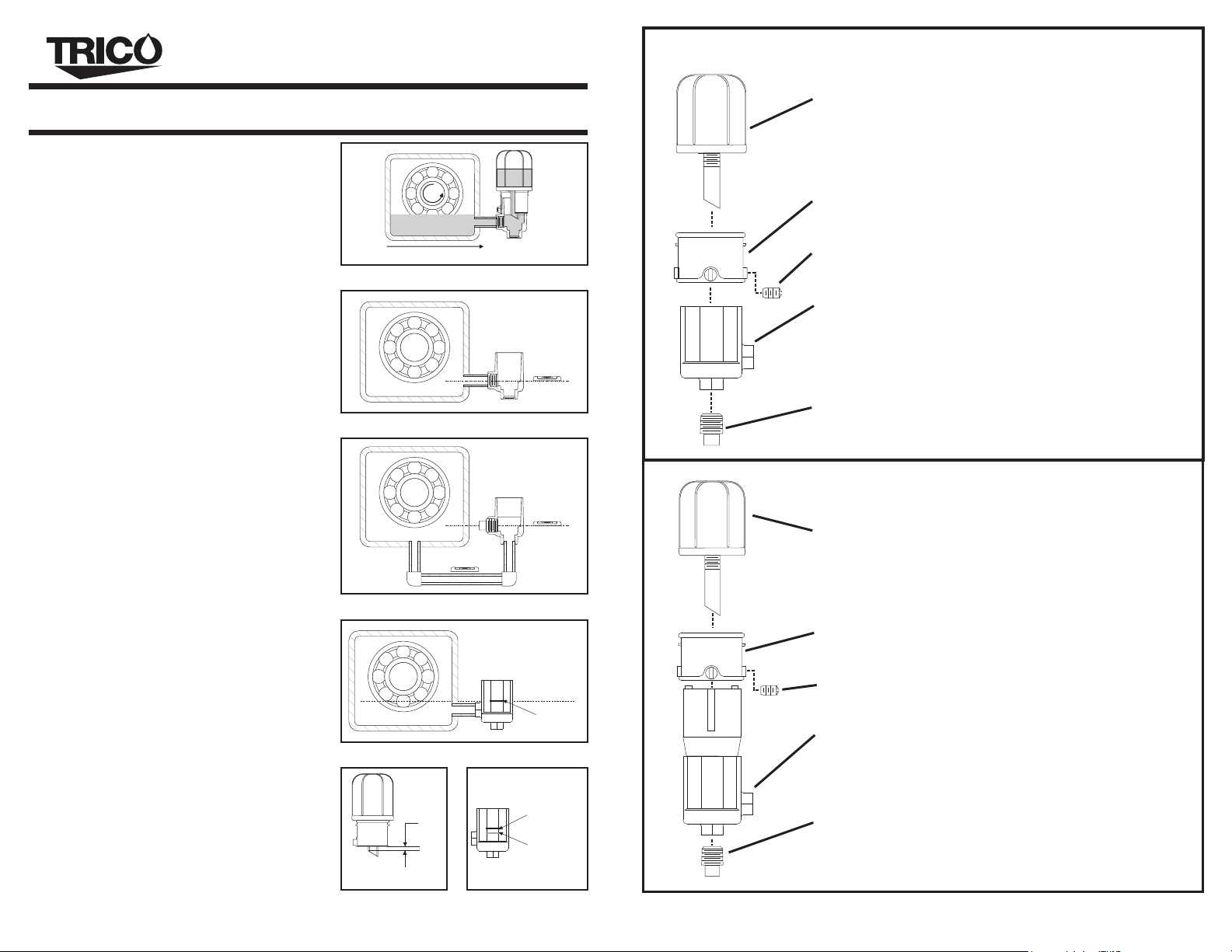
Plastic Opto-Matic Oilers
Spirit
Level
Fig. 2
Spirit
Level
Fig. 3
TRICO CORPORATION 1235 Hickory St., Pewaukee, WI 53072 Phone: (262) 691-9336
www.tricocorp.com 61402 02/19
RESERVOIR FOR
4 oz. (120 ml.)Oilers - 20283R
All types and sizes - 20315R
UPPER CASTING WITH SET SCREWS FOR
SET SCREW ONLY
8 oz. (240 ml.) Oilers - 20284R
All types and sizes - 10310
LOWER CASTING FOR
2 oz. (60 ml.) Oilers - 20282R
Type “E” with ¼ NPT side hole only - 10304
Type “E” with ¼ BSPT side hole only - 14243
PIPE PLUG FOR
Type “EB” ¼ NPT - 10321
Type “EB” with ¼ NPT side and bottom holes - 10306
Type “EB” with ¼ BSPT side and bottom holes - 14241
Type “EB” ¼ BSPT - 14201
“E” & EB” OPTO-MATIC
REPLACEMENT PARTS LIST
LOWER CASTING FOR
Type “EH” with ¼ NPT side hole only - 20330R
Type “EH” with ¼ BSPT side hole only - 22544R
Type “EHB” with ¼ NPT side and bottom holes - 20331R
PIPE PLUG FOR
Type “EHB” ¼ NPT - 10321
2 oz. (60 ml.) Oilers - 20327R
RESERVOIR FOR
8 oz. (240 ml.) Oilers - 20329R
4 oz. (120 ml.) Oilers - 20328R
UPPER CASTING WITH SET SCREWS FOR
SET SCREW ONLY
All types and sizes - 10310
All types and sizes - 20315R
“EH” & EHB” OPTO-MATIC
REPLACEMENT PARTS LIST
3. Loosen set screws on reservoir assembly. Remove
reservoir assembly from lower casting.
4. Be sure all connecting hardware is free from
contaminants (burrs, chips, dirt, etc.) to prevent
clogging or damage to the equipment to be lubricated.
5. Connect lower casting to bearing chamber either
through the side connection, Type E and EH oilers
(Fig. 2) or the bottom connection, Type EB and
EHB oilers (Fig. 3). Use thread compound on
threaded areas.
6. Verify the lower casting is level and parallel with
desired oil level (Fig. 2 and 3). Make necessary
adjustments if needed until lower casting is level.
2. Determine proper oil level, which may be indicated
on the equipment with an arrow. If that is not the case,
engineering drawings or the equipment’s operator
manual can provide the information. Indicate proper
oil level on equipment using a marking device such
as; a marker, scribe, paint, etc.
7. From the oil level mark indicated on the equipment,
use a level to put a mark on the outside of the Opto-
Matic lower casting to indicate where the oil level
should be (Fig 4).
8. Measure the distance between Opto-Matic Oiler
casting edge and top edge of spout angle (Fig 5).
Mark this distance above the original line made in
step 7 on the outside of the Opto-Matic lower casting
(Fig. 6). Now the bottom of the reservoir assembly
can be used as an indicator of oil level.
9. Fill the equipment bearing chamber through the lower
casting until the oil level reaches just below the mark
made in step 7 on the lower casting. DO NOT fill at
or above this mark as it will cause your equipment to
have a high oil level.
10. Use a funnel to fill the reservoir assembly 2/3rds
with the recommended oil.
11. Place thumb over reservoir spout, invert, and insert
on lower casting assembly at the point where the
bottom edge of the reservoir assembly is at the level
“X” mark from step 8. Quickly tighten set screws on
the side of the reservoir assembly.
12. Start up equipment to verify proper oil level is
being maintained.
1. Prior to installing the Opto-Matic Oiler, shaft rotation
direction must be determined, typically indicated by an
arrow on the casting of the equipment. Install oiler on
the side of the equipment facing the direction of shaft
rotation to prevent misfeeding of the oiler (Fig 1).
Fig. 4
Level Line
Oil Level
Fig. 5
X
Fig. 6
Mark from
step 7
Mark Level “X”
TRICO CORPORATION 1235 Hickory St., Pewaukee, WI 53072 Phone: (262) 691-9336
www.tricocorp.com
Fig. 1
Direction of shaft rotation

Read Instructions Before Installing
Plastic Opto-Matic Oilers
Spirit
Level
Fig. 2
Spirit
Level
Fig. 3
TRICO CORPORATION 1235 Hickory St., Pewaukee, WI 53072 Phone: (262) 691-9336
www.tricocorp.com 61402 02/19
PIPE PLUG FOR
Type “EB” with ¼ BSPT side and bottom holes - 14241
Type “EB” ¼ NPT - 10321
Type “EB” ¼ BSPT - 14201
SET SCREW ONLY
Type “E” with ¼ NPT side hole only - 10304
Type “EB” with ¼ NPT side and bottom holes - 10306
UPPER CASTING WITH SET SCREWS FOR
2 oz. (60 ml.) Oilers - 20282R
All types and sizes - 20315R
LOWER CASTING FOR
Type “E” with ¼ BSPT side hole only - 14243
8 oz. (240 ml.) Oilers - 20284R
RESERVOIR FOR
4 oz. (120 ml.)Oilers - 20283R
All types and sizes - 10310
“E” & EB” OPTO-MATIC
REPLACEMENT PARTS LIST
2 oz. (60 ml.) Oilers - 20327R
RESERVOIR FOR
4 oz. (120 ml.) Oilers - 20328R
Type “EHB” with ¼ NPT side and bottom holes - 20331R
Type “EH” with ¼ NPT side hole only - 20330R
Type “EH” with ¼ BSPT side hole only - 22544R
All types and sizes - 10310
UPPER CASTING WITH SET SCREWS FOR
LOWER CASTING FOR
8 oz. (240 ml.) Oilers - 20329R
All types and sizes - 20315R
SET SCREW ONLY
PIPE PLUG FOR
Type “EHB” ¼ NPT - 10321
“EH” & EHB” OPTO-MATIC
REPLACEMENT PARTS LIST
3. Loosen set screws on reservoir assembly. Remove
reservoir assembly from lower casting.
4. Be sure all connecting hardware is free from
contaminants (burrs, chips, dirt, etc.) to prevent
clogging or damage to the equipment to be lubricated.
EHB oilers (Fig. 3). Use thread compound on
threaded areas.
5. Connect lower casting to bearing chamber either
through the side connection, Type E and EH oilers
(Fig. 2) or the bottom connection, Type EB and
6. Verify the lower casting is level and parallel with
desired oil level (Fig. 2 and 3). Make necessary
adjustments if needed until lower casting is level.
2. Determine proper oil level, which may be indicated
on the equipment with an arrow. If that is not the case,
engineering drawings or the equipment’s operator
manual can provide the information. Indicate proper
oil level on equipment using a marking device such
as; a marker, scribe, paint, etc.
7. From the oil level mark indicated on the equipment,
use a level to put a mark on the outside of the Opto-
Matic lower casting to indicate where the oil level
should be (Fig 4).
8. Measure the distance between Opto-Matic Oiler
casting edge and top edge of spout angle (Fig 5).
Mark this distance above the original line made in
step 7 on the outside of the Opto-Matic lower casting
(Fig. 6). Now the bottom of the reservoir assembly
can be used as an indicator of oil level.
9. Fill the equipment bearing chamber through the lower
casting until the oil level reaches just below the mark
made in step 7 on the lower casting. DO NOT fill at
or above this mark as it will cause your equipment to
have a high oil level.
10. Use a funnel to fill the reservoir assembly 2/3rds
with the recommended oil.
11. Place thumb over reservoir spout, invert, and insert
on lower casting assembly at the point where the
bottom edge of the reservoir assembly is at the level
“X” mark from step 8. Quickly tighten set screws on
the side of the reservoir assembly.
being maintained.
12. Start up equipment to verify proper oil level is
1. Prior to installing the Opto-Matic Oiler, shaft rotation
direction must be determined, typically indicated by an
arrow on the casting of the equipment. Install oiler on
the side of the equipment facing the direction of shaft
rotation to prevent misfeeding of the oiler (Fig 1).
Fig. 4
Level Line
Oil Level
Fig. 5
X
Fig. 6
Mark from
step 7
Mark Level “X”
TRICO CORPORATION 1235 Hickory St., Pewaukee, WI 53072 Phone: (262) 691-9336
www.tricocorp.com
Fig. 1
Direction of shaft rotation
This manual suits for next models
1
Other Trico Lubrication System manuals

Popular Lubrication System manuals by other brands


Groeneveld
Groeneveld MultiLine SFi Operation & maintenance manual

Graco
Graco Spindl-Gard 24B219 instructions

Bijur Delimon
Bijur Delimon TMD-5 manual

Perma
Perma CLASSIC Series operating instructions

Bijur Delimon
Bijur Delimon V5 60444 Technical data

Schneider Airsystems
Schneider Airsystems FP-M Original operating manual


