MEMOLUB HPS User manual

1509 Rapids Drive
P.O. Box 044051
Racine, WI 53404
Phone: (800) 635-8170
Fax: (262) 637-4090
www.memolub.com
The
MEMOLUB®HPS
User’s Guide
2.2
PLI, LLC
Power Lube Injection
Represented By:
Revised: November 2005

MEMOLUB®HPS User’s Guide Page 1 of 39 PLI, LLC
TABLE OF CONTENTS
1THE MEMOLUB®HPS ...................................................................................................................................... 3
1.1 OVERVIEW ...................................................................................................................................................... 3
1.2 THE MEMO.................................................................................................................................................... 4
1.2.1 Description............................................................................................................................................. 4
1.2.2 Volumetric Setting of the MEMO ........................................................................................................... 4
1.2.3 Frequency Setting of the MEMO............................................................................................................ 4
1.3 THE LUBRICATOR BODY ................................................................................................................................. 5
1.3.1 Description............................................................................................................................................. 5
1.3.2 Function ................................................................................................................................................. 5
1.4 LUBRICANT CARTRIDGES AND BATTERY PACKS............................................................................................. 6
1.4.1 Lubricant Cartridges.............................................................................................................................. 6
1.4.2 Battery Packs.......................................................................................................................................... 6
1.4.3 Stocking .................................................................................................................................................. 6
1.5 MEMOLUB®EX ........................................................................................................................................... 6
2THE MULTI-POINT LUBRICATION SYSTEM............................................................................................ 7
2.1 FUNCTION ....................................................................................................................................................... 7
2.2 DISTRIBUTION BLOCKS ................................................................................................................................... 7
2.3 COUPLER BRIDGING ELEMENTS ...................................................................................................................... 8
3THE 2-POINT SPLITTER (ALSO KNOWN AS "SPLITTER-MEMO") .................................................... 8
3.1 DESCRIPTION .................................................................................................................................................. 8
3.2 HOW IT WORKS .............................................................................................................................................. 9
3.3 RETROFITTING A MEMOLUB®...................................................................................................................... 9
4THE MEMOLUB®HPS WITH EXTERNAL POWER CONTROL OR SUPPLY ...................................... 9
4.1 THE MEMOLUB®EPC VERSION................................................................................................................... 9
4.2 THE MEMOLUB®EPS: 4.5VDC, 12VDC &24VDC POWERED ................................................................. 10
4.3 THE MEMOLUB®24VDC PLC CONTROLLED VERSION.............................................................................. 11
5ACCESSORIES ................................................................................................................................................. 12
5.1 TUBING ......................................................................................................................................................... 12
5.2 TABLE OF RECOMMENDED PIPE AND TUBING LENGTHS................................................................................ 13
5.3 FITTINGS ....................................................................................................................................................... 13
6INSTALLATION ............................................................................................................................................... 14
6.1 INSTALLING THE MEMO .............................................................................................................................. 14
6.2 OPENING AND CLOSING THE MEMOLUB®HPS .......................................................................................... 14
6.2.1 Opening the MEMOLUB® HPS ................................................................................................................. 14
6.2.2 Closing the MEMOLUB® HPS................................................................................................................... 14
6.3 INSTALLING A GREASE CARTRIDGE .............................................................................................................. 14
6.4 INSTALLING AN OIL CARTRIDGE ................................................................................................................... 16
6.5 TESTING THE MEMOLUB®HPS (CHECK FUNCTION).................................................................................. 16
6.6 MOUNTING THE MEMOLUB®HPS ONTO THE MEMO ................................................................................ 17
6.7 TESTING THE MEMOLUB®HPS (WHILE MOUNTED) .................................................................................. 17
6.8 MAINTENANCE.............................................................................................................................................. 17

7 MOUNTING DO’S AND DON’TS............................................................................................................... 17
7.1 GENERAL ...................................................................................................................................................... 17
7.2 SINGLE-POINT INSTALLATION....................................................................................................................... 17
7.2.1 Direct Installation ................................................................................................................................ 17

7.2.2 Remote Installation .............................................................................................................................. 18
7.3 MOUNTING WITH THE 2-POINT SPLITTER (SPLITTER-MEMO) ..................................................................... 18
7.4 MOUNTING WITH THE PROGRESSIVE DISTRIBUTION BLOCK.......................................................................... 18
8TROUBLESHOOTING .................................................................................................................................... 18
8.1 THE MEMOLUB®HPS DOES NOT WORK ..................................................................................................... 18
8.2 NO LUBRICANT IS COMING OUT OF THE MEMOLUB®HPS .......................................................................... 19
8.3 THE LUBRICANT CARTRIDGE DOES NOT EMPTY CORRECTLY.......................................................................... 19
8.4 LUBRICANT DOES NOT GET TO THE APPLICATION .......................................................................................... 20
9WARRANTY...................................................................................................................................................... 20
APPENDIX................................................................................................................................................................. 21
10.1 MEMOLUB®HPS SPECIFICATIONS ............................................................................................................. 22
10.2 MEMOLUB®HPS DIMENSION DRAWING ................................................................................................... 23
10.3 BASIC PROGRAM SETTINGS........................................................................................................................... 24
10.4 FINE-TUNING YOUR LUBRICATION PROGRAM .............................................................................................. 25
10.5 MULTI-POINT SYSTEM ORDERING INFORMATION ......................................................................................... 26
10.6 MULTI-POINT SYSTEM DISTRIBUTION BLOCK SETUP GUIDE ........................................................................ 28
10.7 2-POINT SPLITTER PROGRAM SETTINGS........................................................................................................ 29
10.8 2-POINT SPLITTER DIMENSIONS .................................................................................................................... 30
10.9 MAINTENANCE ADAPTER INFORMATION....................................................................................................... 31
10.10 INSTALLATION PARTS ................................................................................................................................... 32
10.11 MANUAL LUBRICATION VS.MEMOLUB®AUTOMATIC LUBRICATION ......................................................... 34
10.12 MEMOLUB®EX.......................................................................................................................................... 35
10.13 MEMOLUB®EPC........................................................................................................................................ 36
10.14 MEMOLUB®EPS ........................................................................................................................................ 37
10.15 MEMOLUB®24VDC PLC-CONTROLLED.................................................................................................... 38
10.16 MEMOLUB®24VDC PLC-CONTROLLED INSTALLATION INSTRUCTIONS.................................................... 39
MEMOLUB® HPS has a 2-year limited warranty for replacement due to defects in material and labor. Not
responsible for consequential damages beyond replacement or refund of amount paid. MEMOLUB is a
registered trademark of MEMOLUB International, s.a. © 2003 PLI, LLC.
MEMOLUB®HPS User’s Guide Page 2 of 39 PLI, LLC

MEMOLUB®HPS User’s Guide Page 3 of 39 PLI, LLC
1 The MEMOLUB®HPS
1.1 Overview
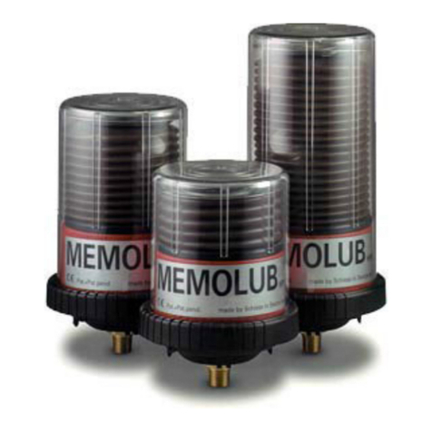
The MEMOLUB®HPS is an automatic, self-contained, electro-mechanical lubricator.
The "HPS" in its name stands for High Pressure System. It ejects grease or oil under
programmable control at an output pressure of 350psi. There are three available models:
Cartridge Capacity
Model 120 (Standard) 120cc ¼ pound
Model 240 (Mega) 240cc ½ pound
Model 480 (Giga) 480cc 1 pound
The MEMOLUB®HPS is a highly versatile device of robust design that can be used to
satisfy a variety of application requirements. Its value and reliability have been proven
through years of use by hundreds of companies in thousands of applications.
The MEMOLUB®is a single-point lubricator that can be mounted directly on the
bearing point, slide, gear, or other object requiring lubrication.
The MEMOLUB®can be mounted remotely for safety, ease of service, or
avoidance of hostile environments.
A single MEMOLUB®HPS becomes a 2-point lubricator when used with the
Splitter-MEMO.
The MEMOLUB®can be used as a miniature, low-cost, central lubrication system
to lubricate from 2 to 12 bearings, using a distribution block.
The MEMOLUB®is easily and quickly programmed to eject lubricant at the desired rate
of output and operates as a self-contained lubricator using a battery pack for its source of
power. The EPC (External Power Control) and EPS (External Power Source) versions
expand the application potential of the MEMOLUB®. These versions can be turned on
and off by the machine on which they are being used. This is a valuable feature when
lubrication is required on intermittently or infrequently used equipment. The EPC version
of the MEMOLUB®is battery-powered. The EPS version is powered by an external
source through a power converter.
Under control of a PLC (Programmable Logic Controller) the MEMOLUB®EPC or
MEMOLUB®EPS can be used to lubricate equipment based upon runtime hours,
machine cycles, time of day, or other criteria:
The basic MEMOLUB®HPS is composed of three parts:
The MEMO, which is used to program the rate of lubricant output.
The MEMOLUB®, consisting of a red motor housing and a transparent dome with
spring and locking ring.

The replaceable lubricant cartridge and battery pack.
1.2 The MEMO
1.2.1 Description
The MEMO regulates the rate of grease output of the
MEMOLUB®HPS. It consists of a brass adapter, a black
plastic timing-ring holder, and three plastic timing rings (one
white, one red, and one black). The MEMO is permanently
fitted onto the bearing or other component, and all
MEMOLUB®HPS lubricators of any size will recognize its
program setting.
1.2.2 Volumetric Setting of the MEMO
The brass adapter is an extension of the MEMOLUB's
pump cylinder. One end has a short ¼” NPT thread
used to mount the MEMO on the bearing. The other
end is an M12x1.50 thread that screws into the
MEMOLUB®lubricator. A set of special stroke-
limiting washers is supplied with each MEMOLUB®
for use in programming the volume of lubricant
ejected on each output cycle.
When the MEMO is used without washers (yielding full piston stroke), the output volume
at each stroke is 0.635cc. For each washer inserted into the brass adapter of the MEMO,
the output volume will decrease by 0.04cc per stroke. A Maximum of 8 washers
(including a lock washer) can be inserted into the brass adapter. If the stroke-limiting
washers are used, the lock washer should be inserted last to hold the others in place. If
only one washer is used, use the locking washer. Important Note: When using the 2-Point
Splitter (see Section 3: The 2-Point Splitter), volumetric setting is not possible.
1.2.3 Frequency Setting of the MEMO
The white, red, and black plastic timing rings are used to set
the frequency of ejection cycles of the MEMOLUB®HPS.
They are inserted into the black plastic ring-holder either
individually or in combination to obtain the desired frequency
of output cycles.
MEMOLUB®HPS User’s Guide Page 4 of 39 PLI, LLC

The seven output frequency settings of the MEMOLUB®HPS are as follows:
Ejection Cycle
Rings Used Code Cycles Per Day Frequency
Red, White, & Black RWB 24 1 Hour
Red & White RW 12 2 Hours
Red & Black RB 4 6 Hours
Red R 2 12 Hours
Black & White BW 1.5 16 Hours
White W 1 24 Hours
Black B 0.5 48 Hours
Using the volumetric program settings described in Section 1.2.2 above, and the
frequency settings shown here, it is possible to achieve 52 different rates of lubricant
output. The output settings are shown on two pages in the Appendix titled “Basic
Program Settings” and “Fine Tuning Your Lubrication Program”.
When the MEMOLUB®HPS lubricator is shipped, all three timing rings are seated in the
plastic holder. To remove them, just use a small screwdriver.
1.3 The Lubricator Body
1.3.1 Description
The lubricator body consists of a red motor housing, a transparent
dome, a spring, a compression plate, a black rubber seal, and a black
locking ring. The red motor housing contains all of the electro-
mechanical parts of the MEMOLUB®HPS. The black rubber seal
covers the battery compartment. Because of the configuration of its
grease cartridge, the Model 480 lubricator does not require this black
seal.
The transparent polycarbonate dome protects the lubricant cartridge
and allows for the easy viewing of lubricant remaining. The spring
and the compression plate maintain the position of the lubricant
cartridge on the inlet valve of the pump in the red housing.
1.3.2 Function
An electric motor drives a gearbox. A cam fitted on the outlet
gear drives a lever which lifts the hollow piston and
simultaneously compresses a spring. When the piston reaches
the top of its stroke, the lever is freed from the cam and the
piston begins its downward (working) stroke, driven by the
spring. Lubricant is sucked into the chamber formed above the piston during its
downward ejection stroke, thus preparing the piston for the next cycle.
MEMOLUB®HPS User’s Guide Page 5 of 39 PLI, LLC

1.4 Lubricant Cartridges and Battery Packs
1.4.1 Lubricant Cartridges
Each size lubricator has its own corresponding lubricant cartridge. Every grease cartridge
is filled with care and precision, and is centrifuged during the filling operation to avoid air
pockets in the cartridge that might create an air lock in the pump. Cartridges are not
reusable. The volume of grease in each cartridge is carefully calculated and the weight of
each cartridge depends on the specific weight of the lubricant inside.
PLI, LLC stocks over 250 different greases and oils for filling
lubricant cartridges, but almost any lubricant with a rating of NLGI-
2 or less is suitable for use in the MEMOLUB®HPS.
PLI does not recommend lubricants for a particular application. If a
MEMOLUB®user is uncertain of the type of lubricant to be used
PLI can often assist by providing general information. We can also
assist by referral to the Technical Services Department of the desired
lubricant manufacturer. These Technical Services Departments offer expert advice on the
lubricant requirements for specific applications and the product in their line best suited to
the need.
1.4.2 Battery Packs
A MEMOLUB®Battery Pack is delivered with each MEMOLUB®HPS replacement
cartridge. Each battery pack can empty a lubricant cartridge while operating at
continuous temperatures as low as the following:
STANDARD Model 120 (120cc) cartridge: +21F (-5C)
MEGA Model 240 (240cc) cartridge: +32F (0°C)
GIGA Model 480 (480cc) cartridge: +41°F (+5C)
For continuous operating temperatures lower than those shown, available cold-weather
lithium battery packs should be used.
Battery packs should be changed every time the lubricant cartridge is replaced to assure
proper voltage to the system; and each battery pack should only be used once. A new
battery pack is supplied with each replacement cartridge purchased.
1.4.3 Stocking
Cartridges and battery packs must be stored in cool, dark conditions (preferably in their
original packaging). The shelf-life of stored batteries is 2 years.
1.5 MEMOLUB®EX
The MEMOLUB®EX is the same self-contained, battery powered lubricator as the
MEMOLUB®HPS model with a modified enclosure rated for limited hazardous
locations. This version is identified by the black motor base housing (see Appendix for
EX Ratings).
MEMOLUB®HPS User’s Guide Page 6 of 39 PLI, LLC

2 The Multi-Point Lubrication System
2.1 Function
Using a MEMOLUB®distribution block, the MEMOLUB®
HPS Multi-Point System can service from 2 to 12 lubrication
points. The distribution block is completely sealed to keep out
airborne contaminants, dust, and dirt, and works on the
principal of piston valves. During operation, a series of pistons
inside the block is actuated by the flow of lubricant from the
MEMOLUB®lubricator. Lubricant flows through a series of
internal channels in the distribution block, when one piston
valve is filled the other is emptied through its output port. The pistons move in a
prearranged sequence to allow for the progressive distribution of lubricant to all lubricant
points.
A built-in check function can be used to confirm that the
system is operating properly. An indicator pin is located
on the last piston of the distribution block. The pin
moves back and forth at the completion of a lubrication
cycle. If there is a blockage anywhere in the system, the
system stops lubricating and the indicator pin ceases to
move. Visual inspection of the indicator pin can be used
to verify proper operation of the system.
To remotely and continuously monitor operation of the system a distribution block with
an optional limit switch is available. An electric circuit is attached to the limit switch. The
limit switch is activated by the indicator pin, which makes or breaks contact in the
electrical circuit. This signal may be tied into a monitoring device to display visual or
audible indication of the systems operation.
2.2 Distribution Blocks
On each output cycle of the distribution block each outlet port ejects .3cc’s of lubricant.
Multi-point systems are available using distribution blocks with an even number of outlet
ports (i.e. 4, 6, 8, and 12). Multi-point lubrication systems are designed using these basic
distribution blocks and the coupler bridging elements described in Section 2.3 below. The
coupler bridging elements permit the design of systems with a number of outlet ports
other than those of the basic distribution block.
MEMOLUB® multi-point lubrication systems are generally delivered to the user pre-
assembled with the specified number (2 through 12) of lubricant outlet ports, charged
with the appropriate lubricant and ready to install. Tubing pre-filled with the desired
lubricant is available in various lengths to facilitate installation. These ready-to-use
systems are termed MEMOLUB®Plug 'n LubeSystems. Empty tubing is also available
which the user may charge with lubricant upon installation.
MEMOLUB®HPS User’s Guide Page 7 of 39 PLI, LLC

On occasion it may be desired to retrofit a previously-purchased MEMOLUB® lubricator
into a multi-point system, or change the number of outlet ports in a multi-point system
that was previously installed. When this occurs, individual distribution blocks and coupler
bridging elements are available from PLI.
PLI and its distributors are always available to assist in the design, layout, and ordering of
a multi-point system appropriate for your needs.
2.3 Coupler Bridging Elements
For those applications requiring an odd number of lube points, coupler bridging elements
may be required for linking two outlet ports together. In this case, the lubricant volume at
the outlet of the coupler will be doubled. For instance, an eight-port distribution block
with two outlet ports linked together by a coupler becomes a seven-port distribution block
with one port receiving twice as much lubricant as the other six ports. Cross-porting using
coupler bridging elements can be advantageous when designing systems in which some
bearings on the system require greater amounts of lubricant than others. The use of
couplers for cross-porting outlet ports on distribution blocks is illustrated and further
explained in the Appendix (see “Distribution Block Set-Up Guide”).
3 The 2-Point Splitter (Also known as "Splitter-MEMO")
3.1 Description
The Splitter-MEMO divides the volume of lubricant at each
ejection cycle of the MEMOLUB®HPS. It is specially designed
for the economical lubrication of two-bearing shaft systems such
as electric motors, pumps, and fans. It transforms the
MEMOLUB®HPS into a two-outlet system.
The Splitter-MEMO can be used with any of the three sizes of
MEMOLUB®HPS lubricators (namely the Model 120, Model
240, or Model 480). Refer to the Appendix for Splitter-MEMO
Output Programming.
The Splitter-MEMO replaces the brass fitting of the normal MEMO. The black plastic
timing ring holder and three colored timing rings are used with the Splitter-MEMO to
program the frequency of lubricant ejection cycles. The black plastic timing-ring holder is
fit onto the Splitter-MEMO in the same manner as on the brass fitting of the standard
MEMO. The Splitter-MEMO comes equipped with 5/16” (8mm) push-in tube fittings on
the outlet ports. Important: The Splitter-Memo can only operate under full-piston stroke.
Do not attempt to insert stroke-limiting washers into the Splitter-MEMO.
It is recommended that the Splitter-MEMO be used with greases having a base-oil
viscosity of no more than 10,000cSt, at working temperature. Check with your
MEMOLUB®distributor, lubricant supplier, or with PLI for base-oil viscosity
information.
MEMOLUB®HPS User’s Guide Page 8 of 39 PLI, LLC

The lengths of tubing that can be used with the Splitter-MEMO applications are
determined by the base-oil viscosity at the working temperature of the grease used. The
table in Section 5.2 provides information on recommended maximum tube lengths to be
used with the Splitter-MEMO. Contact your MEMOLUB®distributor, PLI, or your
lubricant supplier for information on the temperature at which the base-oil of the grease
being used reaches this viscosity.
3.2 How It Works
An explanation of the operation of the Splitter-MEMO, with diagrams, is provided in the
Appendix. Also provided in the Appendix are dimensional drawings of the system when
used with each of the three sizes of MEMOLUB®Lubricators.
Caution: Splitter-MEMO’s are carefully pre-filled to 100% capacity at the factory with
the same grease ordered in the MEMOLUB®cartridge. Do not open the Splitter-MEMO
or manually activate the Stem Valve. In both cases air will be introduced into the system.
3.3 Retrofitting a MEMOLUB®
A MEMOLUB®HPS can be retrofit in the field to a 2-
point Splitter-MEMO. Retrofitting is accomplished by
removing the black timing ring holder from the brass
fitting of the MEMO and placing it on the Splitter-
MEMO.
Retrofitting a MEMOLUB®HPS in the field may require
recharging the Splitter-MEMO with the grease being used.
SPLITTER MEMO's purchased without a MEMOLUB®Lubricator have been pre-
charged with lithium-based grease at the factory. If incompatible grease or a special
grease (e.g. food-grade) is to be used, it will be necessary to recharge the Splitter-MEMO.
To do this, use the Zerk grease nipple that is supplied with the Splitter-MEMO to pump
the correct grease through the outlet port labeled #1 (see illustration above). This is the
outlet port closest to the base of the Splitter-MEMO. The Splitter-MEMO must be
recharged without the MEMOLUB®Lubricator mounted on it. Pump grease into outlet
port #1until it seeps through the piston at the top of the Splitter.
4 The MEMOLUB®HPS with External Power Control or Supply
4.1 The MEMOLUB®EPC Version
MEMOLUB®HPS User’s Guide Page 9 of 39 PLI, LLC
The EPC (External Power Control) version of the MEMOLUB®HPS is
ideal for avoiding over-lubrication in applications where machinery is
used infrequently or intermittently. The MEMOLUB®EPC operates
under its own battery power but the lubricator is turned on and off
externally. A 12” lead-wire extending from the base of the lubricator is
connected to a relay. This relay is opened and closed in concert with

MEMOLUB®HPS User’s Guide Page 10 of 39 PLI, LLC
the on-off switch of the machine on which it is being used. Extension cables and
connectors (as shown in picture at left) are supplied as a part of this system, and relays are
available.
When the relay is closed (machine is operating) the MEMOLUB®operates under its own
battery power and under control of the MEMO program. Upon initial closure of the relay,
the MEMOLUB®goes through an immediate output cycle and then reverts to control of
the MEMO program, except when the MEMO is fitted with all three timing rings (white,
red, and black). In this case, the MEMOLUB®EPC will complete approximately 10
continuous cycles each time power is supplied, before resuming its normal programming.
In any case, when the relay is open the MEMOLUB® ceases operation.
The relay may also be controlled by a PLC, permitting ejection cycles to occur based
upon cumulative hours of machine runtime, clock hours, or some other event determined
by the PLC. For an output cycle to occur, the PLC must close the relay for at least 15
seconds, and there must be a 60-second interval between output cycles. The MEMO
program is not used when operating under PLC control; however a white timing ring
should be in place.
When operating under External Power Control (EPC) the life of the lubricant cartridge
cannot be determined by the setting of the MEMO program. It will therefore be necessary
to estimate cartridge change-out based on the MEMO setting and normal machine runtime
hours or, if used with a PLC, other criteria being used to control ejection cycles.
When the MEMOLUB®EPC is operating under PLC control, the PLC can calculate the
cartridge change-out by counting the number of output cycles ordered, and considering
the programmed output volume and lubricant cartridge size.
Relay contacts must be gold-plated, and the type of relay used will be dictated by the
application. Furthermore, the distance between the MEMOLUB®EPC and the relay will
determine the extension-wire gage and the connector sizes. Refer to the price sheets or
contact PLI, LLC for pricing and availability of relays, cables, and connectors.
4.2 The MEMOLUB®EPS: 4.5VDC, 12VDC & 24VDC Powered
The EPS (External Power Supply) version of the MEMOLUB®HPS operates from an
external power source- 4.5VDC, 12VDC or 24VDC- bypassing the unit’s battery
chamber. A lead-wire extends from the bottom of the lubricator, and must be connected
to an external power source in order to operate. Extension cables and connectors are
provided by PLI, LLC to facilitate this connection.
External Power may be supplied continuously from a transformer, in which case the
MEMOLUBEPS will operate under program control of the MEMO. Functioning will
be identical to that of the standard MEMOLUB®HPS except when the MEMO is fitted
with all three timing rings (white, red, and black). In this case, the MEMOLUB®EPS
will complete approximately 10 continuous cycles each time power is supplied, before
resuming its normal programming.

MEMOLUB®HPS User’s Guide Page 11 of 39 PLI, LLC
Regulated power may also be supplied by a PLC. In this case the program of the PLC may
be used to control the ejection cycles by periodically providing power to the
MEMOLUBEPS. The frequency of lubricant ejection cycles can thus be controlled by
cumulative hours of machine runtime or clock hours, or some other event determined by
the PLC. The duration of the power pulse supplied by the PLC should be approximately 6
seconds. While the MEMO does not control the operation of the unit in this mode of
operation, it must still be in place with the white timing ring installed.
When operating under External Power Supply (EPS) the life of the lubricant cartridge
cannot be determined by the setting of the MEMO program. The frequency of cartridge
change-out is dictated by the PLC criteria (which controls the ejection cycles) and the
volume setting of the MEMO. The PLC calculates the cartridge change-out by counting
the number of output cycles ordered and considering the programmed output volume and
lubricant cartridge size.
PLI, LLC offers several types of power transformers that are compatible with the
MEMOLUB®EPS. If a transformer is purchased elsewhere, it should have the following
characteristics:
High efficiency
Overload/Over-Voltage protection
Short-Circuit Protection
Output Voltage: 4.5- 6VDC, 12VDC or 24VDC
Output Current: 2Amps peak demand, 1Amp working demand
Electrical Wiring
t the outlet of the MEMOLUB®EPS:
+ Brown
- White
Length and type of wire to use between MEMOLUB®EPS and transformer:
AWG 20 (Cross section 2 x 0.5mm²) – 16 feet (5 meters) or less
AWG 18 (Cross section 2 x 1.0mm²) – 33 feet (10 meters)
In the case of pole inversion, the MEMOLUB®EPS will not work. The transformer can
only supply power to one lubricator at a time. For multiple lubricators, multiple
transformers must be used.
4.3 The MEMOLUB®24VDC PLC Controlled Version
The MEMOLUB® 24VDC-PLC Controlled model lubricator is especially designed for
PLC-controlled machinery (or mobile equipment) where a 24VDC power supply is
available. The PLC supplies the power and controls the frequency of output cycles. It
is ideal for lubricating a wide variety of robots, conveyors, and OEM applications.
This model can be used for single-point applications or lubricating from 2 to 12 lube
points with a MEMOLUB® Multi-Point Lubrication System. The MEMOLUB®
24VDC-PLC Controlled model cannot be used with the Splitter-MEMO.

The MEMOLUB®24VDC-PLC Controlled lubricator has
a unique design utilizing a Power-Through Memo which
contains the electrical connections needed to power the
unit. This gives the user the ability to quickly remove the
lubricator for fast lubricant cartridge change-out while
avoiding disconnecting the electrical connections. A 5-
foot extension cable on the Power-Through Memo is
connected to a PLC-controlled power supply. Because
the PLC program controls the frequency of lubrication output cycles, they may be
based upon elapsed clock hours, machine cycles, a count of parts produced, or other
desired criteria. Further control is provided by adjusting the volume of lubricant
ejected on each cycle. A set of 8 special stroke-limiting washers are supplied with each
lubricator. When the Power-Through Memo is used without washers (yielding full
piston stroke), the output volume at each stroke is 0.635cc. For each washer (including
the "C"-shaped lock washer) inserted into the brass adapter of the Power-Through
Memo, the output volume is decreased by 0.04cc per stroke. (Note: The lock washer
should always be inserted last to hold the others in place.) Please refer to the Installation
Instructions in the Appendix.
Output per spacer washers:
0 = 0.63cc/stroke 3 = 0.51cc/stroke 6 = 0.39cc/stroke
1 = 0.59cc/stroke 4 = 0.47cc/stroke 7 = 0.35cc/stroke
2 = 0.55cc/stroke 5 = 0.43cc/stroke 8 = 0.31cc/stroke
Specifications:
* PLC-controlled lubrication cycles
* 2-wire, 5ft extension cable, Brown(+), Blue(-)
* Input voltage: 24VDC
* Max Amps: .5A
* Single cycle duration: 7.5 seconds
* Minimum time between output cycles: 10 Minutes
* Maximum continuous running time: 30 Seconds
* Polarity Protection
5 Accessories
5.1 Tubing
Only tubes rated at a minimum working pressure of 580psi should be used. Polyamide
tubes (air) are not suitable for use with the MEMOLUB®HPS. Keep in mind that a
tube’s pressure resistance diminishes with increased temperature. The following table lists
the appropriate tubing for a particular ambient temperature range:
MEMOLUB®HPS User’s Guide Page 12 of 39 PLI, LLC

Tube Material Working Temperature
Nylon (Rilsan) Less than 158°F (70ºC)
Copper Less than 320°F (160ºC)
Stainless Steel Less than 482°F (250ºC)
Nylon tubes (Rilsan) can be used in most cases. Transparent tubes are not resistant to UV
exposure and should therefore not be used for outdoor applications. Black or colored
nylon tubing should be used when exposure to sunlight is a factor. For moving
components, use tubing that is adequate and appropriate for that application. When in
doubt, consult your tube supplier, your MEMOLUB®distributor, or PLI.
PLI offers tubing of various materials and diameters. This tubing is sold empty (up to 100
feet) or pre-filled with the lubricant of your choice (up to 30 feet). Please note that tubing
with an inside diameter of less than ¼” (6mm) is not recommended for grease
applications.
5.2 Table of Recommended Pipe and Tubing Lengths
The table is based on the following:
Tube internal diameter of 1/4 inch (6mm)
Threads on lube point of no less than 1/8" NPT
No inner pressure present in the component
Base-Oil Viscosity
(@ Working Temp.)
Directly
Mounted
Remote
(Single Point)
w/Splitter
MEMO
w/Distribution
Block
100 cSt ok 40ft (12m) 16ft (5m) 33ft (10m)
700 cSt ok 30ft (9m) 14ft (4m) 24ft (7m)
1000 cSt ok 26ft (8m) 13ft (4m) 20ft (6m)
1500 cSt ok 23ft (7m) 12ft (4m) 18ft (5m)
3000 cSt ok 18ft (5m) 9ft (3m) 15ft (5m)
5000 cSt ok 13ft (4m) 7ft (2m) 11ft (4m)
9000 cSt ok 7ft (2m) 3ft (1m) 7ft (2m)
15000 cSt ok 3ft (1m) N/
A
3ft (1m)
5.3 Fittings
A variety of adapters, tube fittings, and check valves are available from
PLI, LLC or through your MEMOLUB®Distributor. Push-in tube
fittings allow “instant” connection of nylon tubing to the lubricator (in
single-point applications), distribution block (for multi-point
applications), or 2-point splitter. To attach tubing, simply push the tube
into fitting until it can go no further. (Be certain that plastic tubing has a
square cut.) Holding and sealing is accomplished instantaneously. To detach tubing,
simply depress the manual release ring, then pull the tube out of the fitting. Plastic and
brass fittings are good for most applications. For high temperatures, steel and stainless
steel compression fittings are also available. Refer to the Installation Parts section of the
Appendix or call for a listing of available fittings.
MEMOLUB®HPS User’s Guide Page 13 of 39 PLI, LLC

6 Installation
6.1 Installing the MEMO
Before installing the MEMO on the bearing, the user should manually lubricate the
component with the same grease as the one contained in the MEMOLUB®. Caution: Not
all lubricants are compatible. When in doubt, contact PLI, your MEMOLUB®distributor,
or your lubricant supplier.
The MEMOLUB®HPS must be installed in a location where ambient temperature does
not exceed 140F (60ºC) and is not exposed to aggressive or corrosive environment or to
vibrations. In those cases, refer to Section 7.2.2: Remote Installation.
Screw the brass adapter of the MEMO firmly into the bearing or other component. The
black plastic timing-ring holder should be installed with the flat surface on the shoulder of
the brass adapter. The MEMO should be installed with an end wrench of 21mm or 7/8".
6.2 Opening and Closing the MEMOLUB®HPS
6.2.1 Opening the MEMOLUB®HPS
To open, place the lubricator upright on a flat surface. With one
hand on top of the transparent housing, press firmly. With the
other hand, hold the ribbed surface of the locking ring and turn it
counter-clockwise. Remove the locking ring and the transparent
housing.
6.2.2 Closing the MEMOLUB®HPS
To close, use the same technique. Pressing down on the housing,
hold the locking ring by its ribbed surface and turn it clockwise
until it clicks into the locked position. Ensure that the locking
ring locks by holding the ring on its smooth surfaces and turning
clockwise. If the housing is correctly locked into place, it will not
be possible to open it while holding the locking ring on its smooth
surfaces.
6.3 Installing a Grease Cartridge
Replace the grease cartridge using the following procedure:
Open the MEMOLUB®HPS as described above (Section 6.2.1).
MEMOLUB®HPS User’s Guide Page 14 of 39 PLI, LLC

Prime the MEMOLUB®HPS (if
necessary) with a hand grease gun. This
step is required only if the MEMOLUB
was permitted to operate without a
cartridge in place or operate with an
empty cartridge. Do this by placing the
outlet of the hand grease gun on the inlet
of the MEMOLUB®HPS and pumping
until grease appears at the outlet end of
the MEMOLUB®HPS. Two pumps of
grease are generally sufficient.
Lift the black rubber seal back to reveal the
battery chamber, and insert the battery pack
into the red housing by holding it by its
strip. The battery pack has to be inserted
according to the instructions on the red
housing. When the battery pack is inserted,
the motor will be activated for a second.
Put the rubber seal back in place. {Note:
The black rubber seal is not used on the
Model 480, Giga lubricator.}
Remove the paper, disk-shaped label from
the replacement cartridge and fill in the
following sections: “Start Date” and
“Change Date”. The change date is
determined by the programming, which can
be looked up on your programming chart.
Place the label on the inside top surface of
the transparent housing, so that the
information can be viewed from the top of
the lubricator.
Carefully squeeze air out of the cartridge
until grease begins to emerge from the
outlet. This step avoids pump airlock and
ensures an uninterrupted flow of grease to
the piston pump.
MEMOLUB®HPS User’s Guide Page 15 of 39 PLI, LLC

Place the cartridge on the pump inlet of the
red housing. Make certain that the
cartridge neck is well seated on the pump
inlet.
Place spring and compression plate into
the transparent housing, with the
compression plate facing the housing
opening. Then place the housing
assembly (transparent housing, spring
and compression plate) over the lubric
cartridge which is seated on the red base.
The compression plate should be seated
evenly on the lubricant cartridge.
ant
Lock the transparent housing in place with the black locking ring according to
Section 6.2.2.
6.4 Installing an Oil Cartridge
Installing an oil cartridge is similar to that for grease,
as described in Section 6.3, but the oil cartridge
cannot be placed upside down on the red housing
without spilling. First, lift the black rubber seal back
and place the battery pack into the red housing (note:
the Giga model, shown at left, does not use rubber
seal). Insert the identification label, spring, and
compression plate into the transparent housing.
Next, hold the oil cartridge delicately in one hand
and place the red housing on the neck of the
cartridge. While holding the oil cartridge firmly on
the red housing, reverse their position. Place the red housing and cartridge on a hard
surface and place transparent housing on top. Lock as instructed in Section 6.2.2.
6.5 Testing the MEMOLUB®HPS (Check Function)
To ensure that the MEMOLUB®HPS is working, gently push
on one of the three switches at the bottom of the red housing for
a few seconds. The MEMOLUB®HPS will then go through an
ejection cycle. This will confirm that electronics, mechanics and
batteries are okay. It is important that this be done only with a
lubricant cartridge installed. Operating the MEMOLUBHPS
without a cartridge or with an empty cartridge will “un-prime”
the pump (refer to Section 6.3: Installing a Grease Cartridge).
MEMOLUB®HPS User’s Guide Page 16 of 39 PLI, LLC

6.6 Mounting the MEMOLUB®HPS onto the MEMO
Screw the MEMOLUB®HPS lubricator onto the
MEMO (which should already be screwed into the
bearing housing) using care not to damage the threads.
Once the MEMOLUB®HPS is mounted onto the
MEMO, it will immediately start one or two ejection
cycles. This is the test function.
6.7 Testing the MEMOLUB®HPS (While Mounted)
The MEMOLUB®HPS can be checked at any time while in operation. To do so, unscrew
the MEMOLUB®HPS from the MEMO approximately one turn and then screw it back
down (hand-tight). If the unit is working properly, it will immediately complete one
ejection cycle. If, due to a noisy environment, it is not possible to hear the MEMOLUB®
HPS functioning during this test, unscrew the MEMOLUB®HPS completely from the
MEMO, go to a quieter location, and follow the instructions in Section 6.5.
6.8 Maintenance
The MEMOLUB®HPS does not require any specific maintenance. When used in humid
or dusty atmospheres the MEMOLUB®HPS can be cleaned with compressed air or a
slightly damp rag. Important: To clean the MEMOLUB®HPS do not use solvents or
submerse the unit in any liquid. A Dust/Rain cover is available that can also be used to
keep the MEMOLUB®HPS clean.
7 Mounting Do’s and Don’ts
7.1 General
In general, the MEMOLUB®HPS should be installed where it can be easily serviced and
where the operating conditions (temperature, vibrations, etc.) is not too harsh. When
remote installation is necessary, use only fittings and tubing that are appropriate for your
application. The fitting threads should be sealed to assure optimal performance of your
system. To obtain a good seal on all screwed fittings, it is preferable to use Teflon®tape
or a paste.
7.2 Single-Point Installation
7.2.1 Direct Installation
Avoid installing the MEMOLUB®HPS directly onto vibrating components or
components exposed to a harsh chemical environment or temperatures above 120°F. For
those situations, install the MEMOLUB®HPS remotely (see Section 7.2.2). If it is not
possible to install the MEMOLUB®HPS remotely, use appropriate equipment (such as
vibration mounts, special protection baffles, etc…) to protect the lubricator. Ask your
MEMOLUB®distributor or call PLI for more details.
MEMOLUB®HPS User’s Guide Page 17 of 39 PLI, LLC

MEMOLUB®HPS User’s Guide Page 18 of 39 PLI, LLC
The brass fitting on the MEMO has ¼” NPT thread. If the female thread on your bearing
housing is not ¼” NPT, use available reduction fittings. Avoid using a reduction fitting
that is smaller than ¼”-28 straight (if installed vertically) or smaller than 1/8” NPT (if
installed horizontally). Do not install MEMOLUB®HPS horizontally on even slightly
vibrating components. The MEMOLUB®HPS fitted directly on the lube point can be
used with greases having a base-oil viscosity of up to 15,000cSt at working temperature.
For assistance in determining the base-oil viscosity of a lubricant at working temperature,
contact your lubricant supplier or PLI.
7.2.2 Remote Installation
When remotely mounting the MEMOLUB®HPS, tubing should have an inside diameter
of no less than 1/4” (6mm) and should not exceed 40 feet in length when the ambient
temperature is 68°F or higher and when using a lubricant with a base-oil viscosity of
100cSt (refer to table in Section 5.2). When in doubt, consult PLI or your MEMOLUB®
distributor.
7.3 Mounting with the 2-Point Splitter (Splitter- MEMO)
The Splitter-MEMO must be mounted with tubing of 1/4” (6mm) minimum internal
diameter and with lubricant having a maximum base-oil viscosity of 9,000cSt at working
temperature (refer to the table in Section 5.2). Best results will be achieved when both
tubes are the same length.
7.4 Mounting with the Progressive Distribution Block
Use only progressive distribution blocks supplied or recommended by PLI. Using other
distribution blocks could lead to malfunctions and overall mechanical failures.
When mounting, do not obstruct the inlet valve of the distribution block with sealing paste
or any other sealing material. Never plug an outlet on the distribution block with
anything other than a coupler element provided by PLI (see Section 2.3). Doing so would
completely stop lubricant flow in the system. The MEMOLUB®distribution blocks have
1/8” BSPT inlet and outlet threads.
If the need arises, it is possible to install the MEMOLUB®HPS remotely up to 6 feet
from the distribution block. When this is done, however, the distance between distribution
block and lube points will have to be reduced by the same length. Some grease may not
be suitable for use with the distribution block.
8 Troubleshooting
8.1 The MEMOLUB®HPS does not work
Perform a manual test of the MEMOLUB®HPS by using a MEMO with all three timing
rings in the ring-holder. If the MEMOLUB®HPS does not work, check the following:
Is there a battery pack in the MEMOLUB®HPS and is it correctly inserted?
Are the batteries okay? Use another battery pack to check.

MEMOLUB®HPS User’s Guide Page 19 of 39 PLI, LLC
Is there a plastic ring inside the ring-holder? If not, no switch will be activated and
the MEMOLUB®HPS will not work.
8.2 No lubricant is coming out of the MEMOLUB®HPS
If the MEMOLUB®HPS does function, and no grease comes out of the unit when doing a
manual test, consider the following:
Is there a lubricant cartridge installed? If not, recharge the unit with a cartridge as
described in Section 6.3.
Were the spring and compression plate inserted correctly inside the transparent
housing dome? (See Section 6.3)
Is the pump of the MEMOLUB®HPS primed? If the MEMOLUB®HPS cartridge
was completely emptied before replacement, some air could have been sucked into
the system and the pump would be pumping air for a certain number of cycles.
Place a hand grease gun on the inlet of the red housing and pump grease through
the unit (See Section 6.3). If a grease gun is not available, prime the pump by
manually cycling the MEMOLUB®approximately 10 times while the new
cartridge is in place (see Section 6.5).
8.3 The lubricant cartridge does not empty correctly
If the MEMOLUB®HPS functions and lubricant is ejected, however, the lubricant
cartridge does not empty or not in the predicted timing, check the following:
Is the tubing clogged? Use a hand grease gun to clear tubing.
Is one of the outlets of the distributor block obstructed? Use a hand grease gun and
maintenance adapter (available through PLI) to flush the distribution block until
grease runs freely from all ports in equal amounts.
Is tubing damaged? Replace tubing.
Is counter-pressure higher than 290psi? Only use tubing with ¼” (6mm) inner
diameter or more, fittings with 1/8” NPT threads or higher, and a maximum 12-
point distribution block. When counter-pressure is between 290psi and 350psi, the
MEMOLUB®HPS will empty at a slower pace.
At working temperature, the base-oil viscosity of the grease is higher than what’s
described in 5.2 Table of pipe and tubing lengths. Use a grease appropriate for
your application.
The constant temperature where the MEMOLUB®HPS is used is too cold for the
standard alkaline battery pack. Use cold weather (Lithium) battery packs in
extreme cold situations (refer to section 1.4.2: Battery Packs).
Other manuals for HPS
3
Table of contents
Other MEMOLUB Lubrication System manuals
Popular Lubrication System manuals by other brands

SKF
SKF LINCOLN P203 Assembly instructions

SAFEMATIC
SAFEMATIC IF-103 User interface description

DROPSA
DROPSA VIP4Tools/Oil User and maintenance manual

Bijur Delimon
Bijur Delimon M2500G operating instructions

IMI NORGREN
IMI NORGREN L64C Installation & maintenance instructions

Pentair
Pentair Lincoln PORTABLE LUBRIGUN 917-57 quick start guide