Whyte WM508L User manual

Multiswitch
INSTRUCTION MANUAL
WM508L | WM512L | WM516L | WM524L | WM532L
www.whytetechnologies.com
In the interest of connuous improvement,
all specicaons of products within this brochure are
subject to change without noce.

CONTENTS
Safety
Precauons
Guarantee
General Descripon
Product Descripon
Technical Descripon
Installaon Instrucons
Example Conguraon
Specicaons
3
3
3
4
5
6
6
9
10
2

SAFETY
The Whyte Series 5 Lite Mulswitches are intended for indoor use only.
Do not install the Mulswitch in damp, humid, hot or dusty areas.
Switch o and remove the power supply when making connecons to the
Mulswitch to avoid damaging the unit.
Always earth bond the Mulswitch using the Earth Bonding Lug and/or the
Earth Terminal Bars to a suitable earth bonding point using minimum 4mm²
diameter earth cable.
PRECAUTIONS
To ensure trouble free operaon:
Do not remove the cover of the Mulswitch or disassemble it as this will
invalidate the guarantee.
The female F connectors on this unit were designed for use with '100' type
coaxial cable with a centre core diameter of 1mm². When using larger 125 or
167 cables, you must ensure that suitable F connectors with reducing pins
are used otherwise damage to the unit will occur which will invalidate the
guarantee.
Do not over ghten the F connectors (nger ght only).
GUARANTEE
All Whyte products are guaranteed for a period of 4 years from the date of
purchase against defects. Within this guarantee period, Whyte Technologies
will repair or replace the faulty product. In the unlikely event, please return
any faulty products to your dealer.
The Guarantee will be deemed as void if the serial number on the product
is removed, damaged or illegible. The Guarantee excludes defects caused by
incorrect use, accidental damage, disassembly, water/re/lightning damage or
lack of venlaon.
3

GENERAL DESCRIPTION
The Whyte Series 5 Lite Mulswitch range is ideal for SAT and TERR
distribuon in domesc installaons and small apartment blocks. This high
quality Mulswitch is compable with Quad or Quaro LNB’s and comes in
a range of models including 8, 12, 16, 24 and 32-Way output. The Whyte
Series 5 Lite range is RED compliant and has a built in selectable 4G/5G lter
for excellent rejecon of LTE signals.
The Whyte Series 5 Lite range features superior low-noise performance
and comes complete with a separate Power Supply Unit. This enables these
Mulswitches to be powered locally or remotely, via an extended coaxial
cable. In addion, there is a TERR gain switch and a switchable 12V supply to
power a masthead amplier where required.
Features include:
RED Compliant
Quad and Quaro LNB compable
Hi quality Standalone Mulswitch with 4 years warranty
Industry leading performance at a compeve price
Switchable 4G/5G Filter
Colour coded inputs
Selectable 4G/5G lter
LED power indicator
Includes separate Power Supply Unit with F-Type DC Lead
Switchable 12V supply to power Mast Head Amplier
Adequate clearance to route cables under the Mulswitch
4

1. SAT Inputs
2. TERR Input
3. Corner Brackets
4. Auxiliary 18V Input
5. LED Power Indicator
6. Subscriber Outputs
7. TERR Gain Switch
8. TERR 12V Switch
9. 4G/5G Filter Switch
10. Earth Lug
DC IN 18V
GDN
6
6
107
8
9
4
1
1
2
3 3
3 5 3
87~790 MHz
950~2150 MHz
10dB/0dB±2dB
2±2dB
95dBµV
95dBµV
500mA Max
Quad & Quattro LNB Compatible Multiswitch
Freq Range TERR
Freq Range SAT
Gain TERR
Gain SAT
Max Output TERR
Max Output SAT
LNB Power
WM516L
TERR Gain
TERR 12V
ON OFF
4G 5G
0dB 10dB
TERR Filter
PRODUCT DESCRIPTION
5
Model WM516L shown for illustrave purpose only

TECHNICAL DESCRIPTION
Whyte Series 5 Lite Mulswitches are compable with Quad and Quaro
LNB’s. The inputs are colour coded for ease of installaon which is especially
useful when using a Quaro LNB. For convenience, exisng satellite dishes
which are already ed with a Quad LNB may be used, whereby the drop
cables can be connected to the SAT inputs in no parcular order.
The Series 5 Lite range is RED Compliant and provides a nominal gain of
2dB(±2dB) for Satellite and 10dB(±2dB) Terrestrial Recepon. To facilitate the
recepon of FM and DAB radio at the outlets, the FM and DAB aerials must
be combined with the Terrestrial TV Aerial using a Triplexer. The combined
signals are then connected the TERR input of the Mulswitch.
A high rejecon switchable 4G/5G lter is ed to avoid interference from
LTE signals. If required, a Terrestrial mast amplier can be powered via the
mulswitch by seng the 12V switch to the “ON” posion. If a mast amplier
is not being used, this switch must be le in the “OFF” posion. The TERR
gain can be set to 0dB or 10dB via the TERR Gain Switch.
The Power Supply Unit provided must be connected to the 18V DC Input.
This will power the Mulswitch as well as provide power to the Satellite LNB
inputs. A maximum of 500mA LNB power is available which enables the use
of a line powered launch amplier if required.
If a local mains supply is not available such as in los and outdoor cabinets,
the Power Supply Unit may be conveniently ed elsewhere whereby the
18V DC F-Type lead can be extended using coaxial cable.
INSTALLATION INSTRUCTIONS
MOUNTING THE MULTISWITCH
Select a suitable locaon to install the Mulswitch. Do not install the
Mulswitch in damp, humid, hot or dusty areas. Using the screw slots on the
Corner Brackets, secure the Mulswitch using the supplied xing screws or
other xing to suit the relevant wall surface or cabinet.
6

CONNECTING THE SAT & TERR INPUT CABLES
Use a suitably sized Satellite Dish to provide adequate signal levels from the
satellite being received. Ensure that the Satellite Drop Cables are connected
correctly in the corresponding order with respect to the LNB and the
Mulswitch SAT inputs (Quaro LNB only). Ensure that the F Connectors are
properly sealed against water ingress.
If a Composite Cable (mul core coaxial cable) has been used, ensure that the
outer jacket is not facing upwards and cannot collect rain water. Check the
Terrestrial Drop Cable and ensure that this has also been sealed against water
ingress. If a Triplexer has been used to combine FM and DAB aerials with the
UHF Terrestrial Aerial, ensure that this is also water ght. Ensure that all drop
cables have drip loops prior to their entering the building.
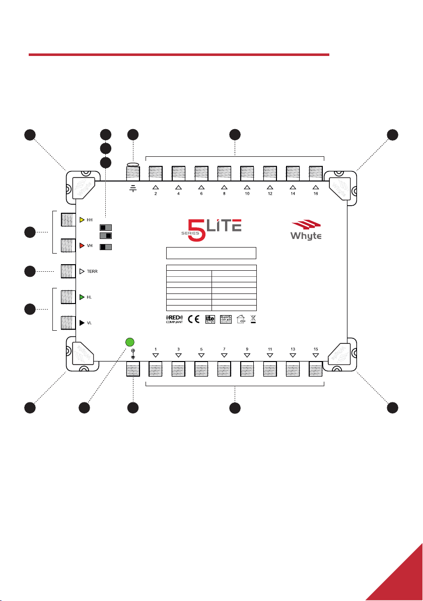
Connect the SAT and TERR drop cables to the corresponding Satellite & TERR
Inputs of the Mulswitch.
CONNECTING THE SUBSCRIBER CABLES
Terminate the Subscriber Cables with good quality F Connectors and connect
to the Subscriber Outputs. The F Connectors should be ed to the coaxial
cable correctly, ensuring that the centre core protrudes 3mm above the F
Connector body. See gure 3 (on page 8). Ensure that you do not exceed the
bending radius of the Coaxial Cable being used.
The Subscriber Cables may be arranged either side of the Mulswitch before
being terminated and connected. If required, the Subscriber Cables may
be arranged to one side of the Mulswitch, with the cables passing under
the Mulswitch before being terminated and connected to the Subscriber
Outputs on the opposite side. See gure 4 (on page 8). Always use approved
high quality coaxial cable.
EARTH BONDING
Earth bond the Mulswitch to the Earth Bonding Lug using minimum 4mm²
Earth Bonding Cable. Make sure that the Earth Bonding Cable is connected
directly to the building’s PME (Protecve Mulple Earthing) point. Matching
Whyte Technologies Earth Bonding bars for your Mulswitch are available
from Whyte Technologies distributors.
7

CONNECTING THE POWER SUPPLY UNIT (PSU)
The PSU must be xed to the relevant wall surface using the appropriate
xings. Connect the DC F-type lead to the 18V DC Input of the Mulswitch.
Once all connecons have been made, connect the plug to a 240V AC
(110V AC) socket to power up the Mulswitch. If a local mains supply is not
available such as in los and outdoor cabinets, the Power Supply Unit may
be conveniently ed elsewhere whereby the 18V DC F-Type lead may be
extended using coaxial cable.
3mm
Figure 3
Figure 4
DC IN 18V
GDN
87~790 MHz
950~2150 MHz
10dB/0dB±2dB
2±2dB
95dBµV
95dBµV
500mA Max
Quad & Quattro LNB Compatible Multiswitch
Freq Range TERR
Freq Range SAT
Gain TERR
Gain SAT
Max Output TERR
Max Output SAT
LNB Power
WM516L
TERR Gain
TERR 12V
ON OFF
4G 5G
0dB 10dB
TERR Filter
8

EXAMPLE CONFIGURATION
SAT
TV FM DAB
PSU-08A
WM516L
SAT2SAT1
TV FM DAB
SAT2SAT1
TV FM DAB
SAT
TV FM DAB
9

SPECIFICATIONS: WM508L
SAT
TERR
SAT
TERR (switchable gain)
SAT Trunk Input
TERR Trunk Input
SAT Tap Output
TERR Tap Output
SAT (IMA³ 35dB)
TERR (IMA³ 60dB)
Trunk-Trunk Input
Cross-Polarity Tap
Via DC In
TERR Input Only
Frequency Range
4G/5G Switch RED Compliant
Input (F-Type Female)
Tap Outputs (F-Type Female)
Gain
Return Loss
Max Output Level
Isolaon
Impedance
Switching Commands
Power Supply Voltage
Powering
Current Consumpon (Max) @ 18V
Power Indicaon
18V DC 800mA PSU Included (WP-0.8A)
Masthead Power Supply (Switchable)
Earth Lug
Dimensions WxLxH (mm)
Weight
950-2150MHz
87-790MHz
YES
4 SAT + 1 TERR
8
2±2dB
10dB/0dB±2dB
>11dB
>8dB
>11dB
>10dB
95dBµV
95dBµV
≥65dB
≥30dB
75Ω
13/18V / 22kHz
18V DC
YES
190mA
LED
YES
12V DC 100mA
Up to 6mm² core
161 x 152 x 43mm
398g
MODEL WM508L
10
The EU Declaraon of Conformity can be viewed at www.whytetechnologies.com.

WM512L | WM516L | WM524L | WM532L
950-2150MHz
87-790MHz
YES
4 SAT + 1 TERR
24
2±2dB
10dB/0dB±2dB
>11dB
>8dB
>11dB
>10dB
95dBµV
95dBµV
≥65dB
≥30dB
75Ω
13/18V / 22kHz
18V DC
YES
200mA
LED
YES
12V DC 100mA
Up to 6mm² core
288 x 152 x 43mm
696g
950-2150MHz
87-790MHz
YES
4 SAT + 1 TERR
16
2±2dB
10dB/0dB±2dB
>11dB
>8dB
>11dB
>10dB
95dBµV
95dBµV
≥65dB
≥30dB
75Ω
13/18V / 22kHz
18V DC
YES
190mA
LED
YES
12V DC 100mA
Up to 6mm² core
234 x 152 x 43mm
554g
950-2150MHz
87-790MHz
YES
4 SAT + 1 TERR
12
2±2dB
10dB/0dB±2dB
>11dB
>8dB
>11dB
>10dB
95dBµV
95dBµV
≥65dB
≥30dB
75Ω
13/18V / 22kHz
18V DC
YES
190mA
LED
YES
12V DC 100mA
Up to 6mm² core
234 x 152 x 43mm
530g
950-2150MHz
87-790MHz
YES
4 SAT + 1 TERR
32
2±2dB
10dB/0dB±2dB
>11dB
>8dB
>11dB
>10dB
95dBµV
95dBµV
≥65dB
≥30dB
75Ω
13/18V / 22kHz
18V DC
YES
190mA
LED
YES
12V DC 100mA
Up to 6mm² core
352 x 152 x 43mm
840g
WM516LWM512L WM524L WM532L
11
In the interest of connuous improvement, all specicaons of products are subject to change without noce.

Unit 13, Watermill Business Centre. Edison Road, Eneld. EN3 7XF
Tel: 0330 999 1980 | [email protected] | www.whytetechnologies.com
Copyright © Whyte Technologies June 2020 - Rev.2
This manual suits for next models
4
Table of contents
Other Whyte Switch manuals
Popular Switch manuals by other brands

red lion
red lion N-Tron NT24K-TX8 Hardware manual

HunterDouglas
HunterDouglas Powerview Gen 2 quick start guide

ExtremeSwitching
ExtremeSwitching X8 Series Hardware installation guide

Silvercrest
Silvercrest KH 2346 operating instructions

TV One
TV One MX-3141PCA instruction manual

BZB Gear
BZB Gear BG-HDVS42U user manual