manuals.online logo
Brands
  1. Home
  2. •
  3. Brands
  4. •
  5. Regent Lighting Solutions
  6. •
  7. Outdoor Light
  8. •
  9. Regent Lighting Solutions Europa Pro User manual

Regent Lighting Solutions Europa Pro User manual

BOLT CAGE ORIENTATION
PATHWAY/LIGHT SOURCE
(Access Door)
Service Side
1
2
www.regentlight.co.za
INSTALLATION INSTRUCTIONS
ALL CONNECTIONS TO BE CARRIED OUT BY A QUALIFIED ELECTRICIAN
1
PLEASE READ CAREFULLY BEFORE STARTING INSTALLATION.
Regent Lighting reserves the right to change specifications modify designs and discontinue items without
incurring obligation and whilst every effort is made to ensure that descriptions, specifications and other
information in this catalogue are correct, no warranty is given in respect thereof and the company shall not be
liable for any error therein.
ALL LUMINAIRES SUPPLIED AND TO BE INSTALLED ABOVE AND BELOW 5 METERS ARE IN COMPLIANCE WITH SANS
60598 SECTION 3.5.6 ACCORDING TO THE MANUFACTURER GUARANTEE AND WARRANTY
WARNING: TO AVOID FIRE, SHOCK OR DEATH
TURN OFF POWER AT CIRCUIT BREAKER OR FUSE AND TEST THAT THE POWER IS OFF BEFORE WIRING
Electrical products can cause death, injury, or damage to
property. Installation of this product must be carried out by a
qualified electrician, in compliance with SANS 10142 or
corresponding regulations of the country of installation. On
completion of installation, the Certificate of Compliance must
be updated.
Europa Pro Post Top - Rectangular Plinth Mounted
0º & 15º installation
Electronic Control Device
WARNING
Electronic Control Device
WARNING
3 - 13 MAIN REEF SERVICE ROAD, CORNER
SPRINGBOK AND MAIN REEF ROAD, INDUSTRIA,
JOHANNESBURG. SOUTH AFRICA.
TEL : +27 11 474 0171
www.regentlight.co.za
RE GENT L I GHT ING A D IVIS ION OF WAH L
IN DUST RIES.
DO NOT CONNECT THE FITTING LIVE
DO NOT PLUG
(CONNECT) WHEN
LIVE AS IT WILL CAUSE
DAMAGE TO THE
LUMINAIRE.
November 2022
Save These Instructions for Future Reference
ELECTRIC SHOCK
HAZARD
This equipment is to be
serviced by trained
personnel only.
ELECTRIC SHOCK
HAZARD
This equipment is to be
serviced by trained
personnel only.
ŸIf the main supply
power (live) is on, it will
cause damage to the
luminaire.
A. Ensure the electrical cable is
fed through the mounting hole.
B. Insert the bolt cage into the
mounting hole and feed the
electrical cable through the
bolt cage towards the surface,
ensuring the cable is fed parallel
to the pathway.
Requirements:
ŸBe sure the electricity to
the system you are working
on is isolated.
1. Ensure the pole is installed
correctly.
C. Insert the bolt cage into the
ground, ensuring the bolt cage
is install correctly.
0º & 15º installation
Europa Pro Post Top - Plinth Mounted
Finished oor
Surface
stubby
Buried
stubby
Bolt
cover
box
Exposed bolts
No visible
mounting bolts
from base plate.
Bolts to adjust
height and
level of the
stubby before
casting in
concrete
Bolts hidden
underneath
cover box
Ground
Level
A
B
Ground Level
Ensure the correct mounting
base is use according to the order.
Visible
mounting bolts
from base plate.
Single way
Double way
15º
0º
www.regentlight.co.za
2
3
4
7
8
5
6
This product should be installed by a competent person i.e. Qualified electrician.
This product requires a constant stable electrical supply 220V - 240V VAC 50Hz - alternating current.
The product must be regularly maintained, including the replacement of lamps/LED timeously.
This product could be HAZARDOUS if not used correctly, it could cause electric shock, serious bodily harm or death.
This product is not a toy, please keep away from children.
This product may contain small parts that can be swallowed.
Use only the correct light bulbs/LED as stipulated on the carton for the product.
Any modifications of this product after supply will result in the guarantee being void.
Spare parts may become unavailable over time.Items can vary slightly from the picture on the carton
Coastal humidity can affect the longevity of the light fitting over time.
Be sure to follow the steps in the order given.
Read instructions carefully.
Important Safety Instructions
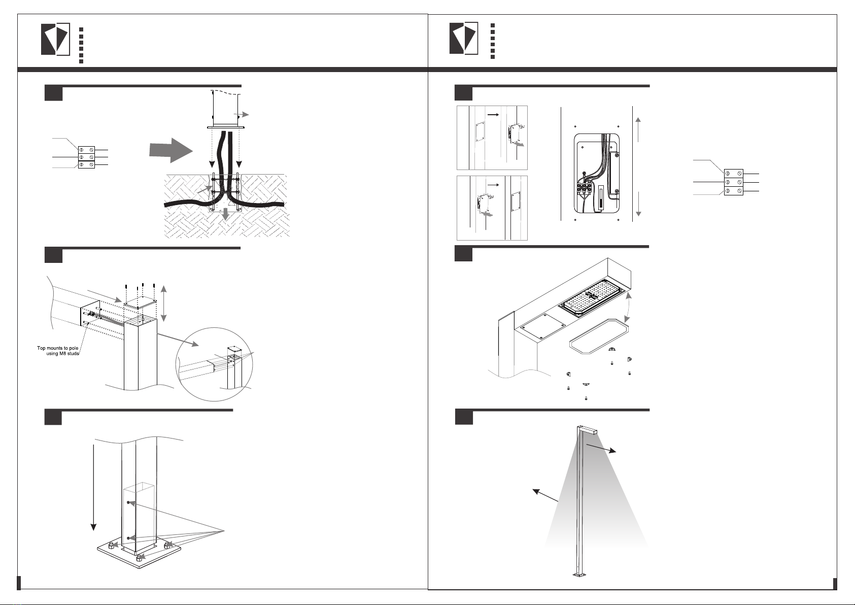
3. A. Remove the pole top
cover.
B. Using the electrical tail
supplied from the fitting, feed
t he c a b le t h r ou g h t h e
locating hole on the top of
the pole, down the pole to
the access door.
C. Align and fasten the fitting
to the pole through the
locating holes either at 0º or
a t 1 5 º. O n c e s e c u r e l y
fastened, align and fasten
the pole top cover.
5. A. Remove the access door via the
four stainless steel fasteners using an
allen key.
B. Connect the cable from the fitting
in the pole to the connector block
through the access door.
C. Replace the access door via the
four stainless steel fasteners using an
allen key.
Mains to
Luminaire
Earth Loop
Green/Yellow
Switch
Wire Red
Neutral loop
Black or Blue
(L) Brown
(E) Green/Yellow
(N) Blue
Stubby
Bolt Cage
PATHWAY
Cable entry Mounting holes
Mains to
Luminaire
Earth Loop
Green/Yellow
Switch
Wire Red
Neutral loop
Black or Blue
(L) Brown
(E) Green/Yellow
(N) Blue
6. To install or change the LED, unscrew
the four stainless steel thumb screws on
the glass and remove the glass from
the fitting, and allow the glass to hinge
on the securing cable.
Ensure the new LED is the correct
w a t t a g e , a c c o r d i n g t o t h e
specification and is securely located
on the mounting surface.
Ensure that the gasket is securely in
place.
Replace the glass via the four stainless
steel thumb screws. Ensure there is no
exposed conductors or loose strands.
7. Switch on the power
supply.
7
Post top light
direction
Access door
direction
Ensure that the pole is
installed in the correct
position/direction.
4. Carefully fasten the pole
with the secured fitting to the
mounting stubby using the
stainless steel structural bolts
and nuts (supplied).
Ensure that there are no
exposed conductors, loose
strands or trapped/pinched
insulation between the pole
and the stubby.
Slide pole
onto stubby
A
B
C
Structural bolts
and nuts
Remove access door.
A
Replace access door.
C
Connect power
to the tting.
To Luminaire
Mains power
B
L N
0° & 15° angle is mounted
the same way
Connect the Switched Live (S/A),
Neutral (N) and Earth (E) cable(s)
to the MCB and connector block
in the access door.
2. Remove the access door. Feed
the ca ble from the gr ound
through the glands at the bottom
of the fitting to the access door.
NEUTRAL – (Black or Blue) to
terminal marked N
EA RT H – (G re en /Ye ll ow ) to
terminal marked.
SWITCHED LIVE – (Red or Brown)
to terminal marked L

Other Regent Lighting Solutions Outdoor Light manuals

Regent Lighting Solutions Lumina Mini User manual

Regent Lighting Solutions

Regent Lighting Solutions Lumina Mini User manual

Regent Lighting Solutions IRIS Series User manual

Regent Lighting Solutions

Regent Lighting Solutions IRIS Series User manual

Regent Lighting Solutions Bedford Bollard - Plinth Mounted User manual

Regent Lighting Solutions

Regent Lighting Solutions Bedford Bollard - Plinth Mounted User manual

Regent Lighting Solutions Bedford Bollard - Buried User manual

Regent Lighting Solutions

Regent Lighting Solutions Bedford Bollard - Buried User manual

Regent Lighting Solutions Europa Pro Post Top User manual

Regent Lighting Solutions

Regent Lighting Solutions Europa Pro Post Top User manual

Regent Lighting Solutions Penza User manual

Regent Lighting Solutions

Regent Lighting Solutions Penza User manual

Regent Lighting Solutions Kazo User manual

Regent Lighting Solutions

Regent Lighting Solutions Kazo User manual

Regent Lighting Solutions Bilux Inground User manual

Regent Lighting Solutions

Regent Lighting Solutions Bilux Inground User manual

Regent Lighting Solutions Halo User manual

Regent Lighting Solutions

Regent Lighting Solutions Halo User manual

Regent Lighting Solutions Plato User manual

Regent Lighting Solutions

Regent Lighting Solutions Plato User manual

Regent Lighting Solutions Columbia User manual

Regent Lighting Solutions

Regent Lighting Solutions Columbia User manual

Regent Lighting Solutions Challenger Mini User manual

Regent Lighting Solutions

Regent Lighting Solutions Challenger Mini User manual

Regent Lighting Solutions T -Line User manual

Regent Lighting Solutions

Regent Lighting Solutions T -Line User manual

Regent Lighting Solutions Echo User manual

Regent Lighting Solutions

Regent Lighting Solutions Echo User manual

Popular Outdoor Light manuals by other brands

Maxim Lighting Carriage manual

Maxim Lighting

Maxim Lighting Carriage manual

Malmbergs 99 833 04-05 instruction manual

Malmbergs

Malmbergs 99 833 04-05 instruction manual

Acuity Brands Lighting Pedestrian LED Luminaire Series Installation and maintenance manual

Acuity Brands Lighting

Acuity Brands Lighting Pedestrian LED Luminaire Series Installation and maintenance manual

Luminar Outdoor 59268 owner's manual

Luminar Outdoor

Luminar Outdoor 59268 owner's manual

Vistosi TREPAI PT Assembly instruction

Vistosi

Vistosi TREPAI PT Assembly instruction

Tungsram ALIx installation guide

Tungsram

Tungsram ALIx installation guide

Saxby Lighting Severus Outdoor Wall EL-40103 Instruction

Saxby Lighting

Saxby Lighting Severus Outdoor Wall EL-40103 Instruction

NANLITE PavoTube T8-7X user manual

NANLITE

NANLITE PavoTube T8-7X user manual

AEC Q5 Pro Maintenance instructions

AEC

AEC Q5 Pro Maintenance instructions

HEPER ZEROX Hybrid Installation & maintenance instructions

HEPER

HEPER ZEROX Hybrid Installation & maintenance instructions

eLEDing EE800W-SH Series Installation instruction

eLEDing

eLEDing EE800W-SH Series Installation instruction

Haushalt International 70366 quick start guide

Haushalt International

Haushalt International 70366 quick start guide

Portfolio 34253 manual

Portfolio

Portfolio 34253 manual

SW-Stahl S9790 manual

SW-Stahl

SW-Stahl S9790 manual

Hoselink L325 user manual

Hoselink

Hoselink L325 user manual

URBAN OUTFITTERS WIATT Assembly instructions

URBAN OUTFITTERS

URBAN OUTFITTERS WIATT Assembly instructions

LIGMAN HARRIER 4 HA-60215-S installation manual

LIGMAN

LIGMAN HARRIER 4 HA-60215-S installation manual

Beurer TL60 Instructions for use

Beurer

Beurer TL60 Instructions for use

manuals.online logo
manuals.online logoBrands
  • About & Mission
  • Contact us
  • Privacy Policy
  • Terms and Conditions

Copyright 2025 Manuals.Online. All Rights Reserved.