INSTALLATION MANUAL
5.0630.10.04
Netzteil IP65, 25 W, monochrom, nicht dimmbar
Power Supply IP65, 25 W, monochrom, not dimmable
alimentation IP65, 25 W, monochrome, pas dimmable
1. Beschreibung
Netzteil zum Anschluss von max 1 Stück 4 POW-LED Modul,
monochrom für SerieWIBRE 4.0100/4.0102
· IP65 Montagegehäuse
· max. Leitungslänge zwischen Netzteil und
POW-LED Strahler ≤ 100 m
HINWEIS: Die Umgebungstemperatur (ta) des Netztteils darf
im geschlossenem Schutzgehäuse nicht größer als 50°C sein. Dies
wird als Richtwert bei einer Temperatur von ca. 35°C im Raum um
das Schutzgehäuse erreicht. Bei Bedarf sind auf Anfrage projekt-
bezogene Lösungen möglich.
2. Spezifikation
Abmessung: 254x180x111 mm
Gewicht: 0,5 kg
Eingangsspannung: 90–250V-AC
Eingansfrequenz: 50–60 Hz
Power Faktor: 0,95
Ausgangsspannung: 12 V-DC
Ausgangsstrom: 1,2 A
Betriebstemperaturbereich: -10°C – +50°C
Lagertemperaturbereich: -40°C – +85°C
3. Garantiebestimmungen
Folgende Garantiezeiten und Bestimmungen gelten
vomTage der Lieferung an:
· 24 Monate aufWIBRE-Produkte
· Unter die Garantie fallen nachweisbare Material-, Konstruktions-
undVerarbeitungsfehler von seiten des Herstellers.
· Für Schäden, welche durch Nichtbeachtung dieser Betriebsan-
leitung, oder durch unsachgemäße Reparatur entstehen, können
wir keine Garantie übernehmen.
·Schäden durch falsche Handhabungsind von der Garantieausgeschlossen.
· Keine Garantie besteht wenn die Installation nicht korrekt nach den
Bestimmungen vorgenommen wurde, oder beiVerwendung nicht
geeigneter Leuchtmittel.
· Änderungen, die dem technischen Fortschritt dienen, behalten
wir uns vor.
Betrieb des Scheinwerfers nur unter Wasser!
1. Description
Power supply for max 1 x 4 POW-LED modul, monochrom
for serieWIBRE 4.0100/4.0102
· IP65 mounting housing
· max. distance between power supply and
POW-LED light ≤ 100 m
NOTE: The ambient temperature (ta) of the power unit must not
exceed 50°C in the enclosed protective housing. This is a guide value
and reached at a temperature of approx. 35°C in the space around
the protective housing. Project-specific solutions are possible on
request.
2. Specification
Dimension: 254x180x111 mm
Weight: 0,5 kg
Input: 90–250V-AC
Frequency: 50–60 Hz
Power Factor: 0,95
Output Power: 12 V-DC
Output Current: 1,2 A
Operating temperature: -10°C – +50°C
Storage temperature: -40°C – +85°C
3. Warranty conditions
The following warranty times and conditions are valid from
the day of delivery:
· 24 months onWIBRE-Products
· Proven faults appertaining to material, construction or processing
fall under the warranty of the manufacturer.
·We accept no liability for damages arising through negligence of
the operating instructions or improper repair work.
· No liability is accepted for installation carried out contrary to the
instructions or for the use of inappropriate light bulbs.
·We reserve the right to instigate any technical improvements
without prior notice.
Use the light only under water!
WIBRE Elektrogeräte Edmund Breuninger GmbH & Co. KG · Liebigstrasse 9 · 74211 Leingarten/Germany
Telefon: +49 (0) 7131 9053-0 · Telefax: +49 (0) 7131 9053-19 · E-Mail: info@wibre.de 1/2
1. Description
Alimentation pour max 1 x 4 POW-LED module, monochrome
pour sérieWIBRE 4.0100/4.0102
· IP65 boîtier
· distance max. entre alimentation et
dernier projecteur 100 mètres
REMARQUE: La température ambiante (ta) du bloc
d‘alimentation ne doit pas être supérieure à 50 °C dans le boîtier de
protection fermé. Cette valeur de référence de température est att-
einte à une température d‘env. 35 °C dans la pièce autour du boîtier
de protection. Des solutions spécifiques au projet sont possibles sur
demande si nécessaire.
2. Spécification
Dimensions: 254x180x111 mm
Poids: 0,5 kg
Tension primaire: 90–250V-AC
Fréquence primaire: 50–60 Hz
Power Factor: 0,95
Tension secondaire: 12 V-DC
Courant secondaire: 1,2 A
Température de régime: -10°C – +50°C
Température du stockage: -40°C – +85°C
3. Dispositions de garantie
Des périodes de garantie et dispositions suivantes sont
en vigueur au jour de la livraison:
· 24 mois pour les produitsWibre
· la garantie couvre des erreurs de construction démontrables,
de matériel et de traitement de la part du fabricant
· pour des dommages qui résultent de non-respect de ce manuel ou
de réparation inadéquate, nous ne pouvons pas assurer la garantie
· des dommages par une fausse manipulation sont exclus de la garantie
·
aucune garantie n‘existe si l‘installation n‘a pas été entreprise correctement
après les dispositions, ou lors d‘une utilisation de sources non appropriés.
· nous nous réservons le droit de faire des modifications qui résultent
de l‘évolution technique de nos produits
Utilisation le projecteur seulement dans l’eau!
254 111
180
≈ 28
Pb
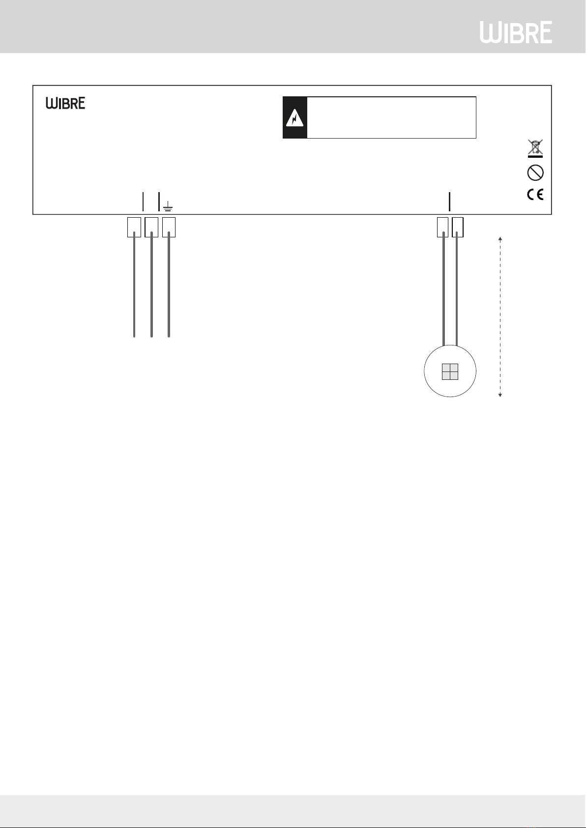
IN
90-250 V-AC,50-60 H z
OUT 1
12 V-DC, 0-25 W
L N PE – +
W443-012-V01
5.0630.10.04 Power Supply
DE | IP65, 12 V-DC, 0-25W, für max 1 Scheinwerfer Serie 4.0100/4.0102
EN | IP65, 12 V-DC, 0-25W, for max 1 spotlights serie 4.0100/4.0102
ta:
-10°C – +50°C
DE | ANSCHLUSSDES SCHEINWERFERS MUSS STROMLOS ERFOLGEN.
ES DARF KEINE PRIMÄRSPANNUNGANLIEGEN.
EN | THE SPOTLIGHT MUST BE CONNECTEDWITHOUT POWER.
NO PRIMARY VOLTAGE MAYBE APPLIED.