Wichard Gyb'Eas User manual

1
Frein de bôme / Boom Brake
Gyb’Easy
www.wichard.com

2
RECOMMENDED INSTALLATION
Gyb’Flex
Gyb’Easy
A: axe de rotation de la bôme
/ boom rotation axis
: Cordage Gyb’Flex /
Gyb’Flex line
B: Poulies / blocks
: Gyb’Easy
G
G
B
B
A
G
B
B
A
Poulies / Blocks
Surface de voile /
Mainsail area Ø Réa (sheave) /
Réf (Part #)
0 - 15 m² Ø 45 / # 63105
16 - 30 m² Ø 55 / # 64105
31 - 40 m² Ø 70 / # 65105
1
2

3
OTHER POSSIBLE INSTALLATIONS
F: Points d’ancrage
Chainplates
C1 : Poulie / Block
C2
: Cordage standard
Standard line
A: axe de rotation de la bôme /
boom rotation axis
: Cordage Gyb’Flex
Gyb’Flex line
G
d
C2
C1
F
F
A
Gyb’Flex Gyb’Easy Poulie / block C1 Cordage standard /
standard line
Poulies / Blocks
Surface de voile /
Mainsail area Ø Réa (sheave) /
Réf (Part #)
0 - 15 m² Ø 45 / # 63105
16 - 30 m² Ø 55 / # 64105
31 - 40 m² Ø 70 / # 65105
F
F
GA
C1
3
4

4
FRANCAIS
I) INTRODUCTION:
Vous venez d’acquérir Gyb’Easy le nouveau frein de bôme Wichard, nous vous remercions de l’intérêt et de la conance que vous
portez à nos produits et espérons que celui-ci vous apportera la plus grande satisfaction.
1) Principe de fonctionnement:
Le frein de bôme Gyb’Easy utilise un cordage spécique Gyb’Flex passant dans une ou plusieurs de ses ouvertures. Les carac-
téristiques du cordage et sa friction sur le frein assurent un freinage de la bôme en souplesse. La progressivité du freinage évite
toute fausse panne et retard à l’empannage. En navigation, le contrôle de l’empannage se fait par la tension du cordage (sans
aucune action sur l’écoute de grand-voile).
2) Réglages de Gyb’Easy :
3 positions de pré-réglages sont possibles (voir ci-dessus) pour s’adapter aux surfaces de grand-voile jusqu’à 40 m² et aux chan-
gements importants des conditions de navigation (ex : passage de force 3 à 6). Plus le nombre de passages est important, plus
le freinage sera puissant. Comme pour tout frein de bôme, quelques essais (dans des conditions de navigation maniables) sont
nécessaires pour bien ressentir le fonctionnement du système. Une fois le bon pré-réglage trouvé, le réglage en navigation se
fait directement du cockpit par la tension du cordage (prévoir l’utilisation d’un winch ou d’un palan). Si une tension trop importante
du cordage est nécessaire au bon freinage de la bôme, utiliser la position de pré-réglage supérieure.
3) Limites de fonctionnement, entretien et précautions d’usage:
Limites de fonctionnement: Gyb’Easy a été conçu pour les grand-voiles jusqu’à 40 m².
ATTENTION: Son bon fonctionnement n’est garanti qu’en utilisant le cordage Gyb’Flex fourni. En cas de changement de celui-ci,
il est impératif de réutiliser le même type cordage (réf Wichard 7148). Pour cela, veuillez vous rapprocher de votre revendeur. An
de garantir votre sécurité et le bon fonctionnement du frein de bôme, veuillez surveiller régulièrement l’usure du cordage. Il est
recommandé de changer ce cordage tous les 5 ans.
Entretien: Gyb’Easy ne requiert aucun entretien particulier. Toutefois il est conseillé de rincer le frein et le cordage régulièrement
à l’eau claire et en cas d’hivernage prolongé, de les démonter.
Précautions d’usage: ATTENTION, même avec un frein de bôme il est tout de même nécessaire de prendre un ris lorsque les
conditions de vent l’exigent. Le cordage Gyb’Flex doit être uniquement utilisé pour cette fonction et en aucun cas pour un autre
usage (écoute, drisse...). Dans tous les cas, le skipper doit toujours faire preuve de sens marin.
II) INSTALLATION:
IMPORTANT : L’installation du système doit toujours être symétrique à l’axe longitudinal du bateau.
1) Installation recommandée avec deux retours au cockpit: voir page 2 schémas 1 et 2
Etape 1 : Installation des poulies de renvoi (B):
Frapper les deux poulies de renvoi (B) suivant le schéma 1 (ex: sur les cadènes de bas hauban arrière). Voir tableau de sélection
des poulies page 2.
Etape 2 : Installation du Gyb’Easy (G):
Fixer le Gyb’Easy (G) sur un pontet sous la bôme en arrière du hale-bas suivant les schémas 1 et 2.
Attention, dans tous les cas, la longueur AG doit être sensiblement égale aux longueurs AB. En l’absence de pontet il est possible
de xer le frein avec un brêlage et une retenue pour éviter le glissement du frein vers l’avant. Toutefois l’installation d’un pontet
est recommandée.
Etape 3 : Installation du cordage Gyb’Flex:
Passer le cordage Gyb’Flex dans l’un des bloqueurs du cockpit ou directement sur un winch. Le passer ensuite dans les 2 poulies
de renvoi (B), puis le renvoyer sur le bloqueur opposé ou directement sur un winch. Assurez-vous que rien ne vienne gêner le
passage du cordage.
Etape 4 : Passage du cordage dans le frein:
Passer une boucle du cordage dans le frein de bôme (voir ci-dessus).
Etape 5 : Coupe du surplus de cordage:
Reprendre le mou du cordage, faire 3 tours sur les winchs, garder au minimum 1m après les winchs et si nécessaire recouper le
surplus de cordage et conserver le reste comme cordage de rechange.
SETTINGS
Strength of the brake
7
6
5

5
ENGLISH
2) Autre possibilité d’installation avec un seul retour au cockpit: voir page 3 schémas 3 et 4
Dans le cas ou l’implantation recommandée n’est pas envisageable, il est possible d’installer le frein de bôme avec un seul retour
au cockpit. Toutefois ce type d’installation nécessite plus de précision de réglage à l’installation, offre moins de souplesse au
freinage et est moins adapté aux grand-voiles de petite taille.
Dans ce cas, le cordage Gyb’Flex ne retourne pas au cockpit, c’est un cordage marin ‘’standard’’ (non fourni) monté en palan qui
permet de régler la tension à partir du cockpit.
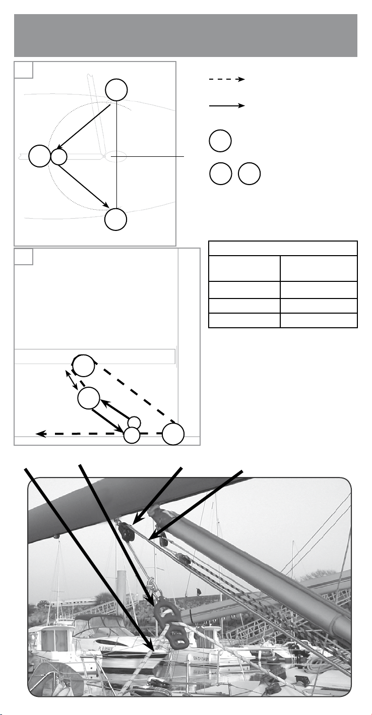
Etape 1 : Choix des points d’ancrage (F) du cordage Gyb’Flex:
ex: cadènes de bas hauban arrière (schéma 3).
Etape 2 : Installation des poulies (C):
Fixer la poulie C1 sur un pontet sous la bôme en arrière du hale-bas puis la C2 au pied de mât suivant le schéma 4. Voir tableau
de sélection des poulies page 3. Attention, dans tous les cas, la longueur AC1 doit être sensiblement égale aux longueurs AF. En
l’absence de pontet il est possible de xer le frein avec un brêlage et une retenue pour éviter le glissement du frein vers l’avant.
Toutefois l’installation d’un pontet est recommandée.
Etape 3 : Installation du cordage de commande ‘’standard’’:
Frapper un cordage ‘’standard’’ à la manille du frein de bôme, le faire passer dans les poulies C1 et C2, puis le faire revenir au
cockpit sur un bloqueur ou directement sur un winch. Voir schéma 4.
Etape 4 : Positionnement du frein de bôme Gyb’Easy:
A l’aide du cordage de commande, positionner le frein Gyb’Easy de façon à laisser une course de tension d’environ 30cm (varia-
ble en fonction de la taille du bateau). Voir schéma 4.
Etape 5 : Installation du cordage Gyb’Flex:
Fixer une extrémité du cordage Gyb’Flex au point d’ancrage bâbord, passer une boucle du cordage dans le frein de bôme en po-
sition 1 (voir photo 5), reprendre le mou du cordage et faire un nœud provisoire sur le point d’ancrage tribord. La distance (d) entre
Gyb’Easy et la poulies C1 doit être d’environ 30 cm (variable selon les bateaux) pour permettre la tension du cordage Gyb’Flex.
Quelques empannages sont nécessaires pour être sûr d’avoir sufsamment de course de réglage (d) et pas trop de distance entre
le frein et la bôme. Voir schéma 4.
Etape 6 : Coupe du surplus de cordage
Après plusieurs empannages et lorsque le bon réglage a été trouvé, recouper le surplus de cordage et conserver le reste comme
cordage de rechange.
III) UTILISATION DU FREIN DE BOME:
> Choisir la position de pré-réglage (nombre de passages dans le frein de bôme) adapté à votre bateau et aux conditions de
navigation.
> Au portant: raidir plus ou moins le cordage Gyb’Flex (ou le cordage de commande standard) pour avoir un passage de bôme en
douceur lors des empannages.
> Au près : mollir le cordage, les virements de bord se font librement.
En cas de changement radical des conditions de navigation nécessitant un changement de réglages.
> Pour votre sécurité, amener le bateau face au vent.
> Relâcher la tension du cordage Gyb’Flex (ou le cordage de commande standard).
> Ressortir la boucle du cordage du frein de bôme.
> Repasser la boucle dans la position la plus adaptée.
IV) GARANTIE:
Wichard garantit tous ses produits contre tout vice de fabrication pour une durée de cinq (5) ans à compter de la date d’achat par
l’utilisateur original. Sont exclus de cette garantie :
> Tout produit qui a été installé de manière inadéquate.
> Tout produit utilisé de manière inappropriée ou pour une application pour laquelle il n’est pas prévu.
> Tout produit non correctement entretenu.
> Tout produit modié sans le consentement écrit de Wichard.
> Tous dommages consécutifs à la corrosion, à l’exposition aux rayonnements ultraviolets ou à l’usure normale des produits.
I) INTRODUCTION:
Thank you for purchasing Gyb’Easy the new Wichard boom brake. We hope that it will bring you great satisfaction.
1) Concept :
Gyb’Easy, the Wichard boom brake uses a specic line called Gyb’Flex passing over the boom brake itself. Thanks to its unique
technical features and the frictions on the brake, the boom is allowed to gybe smoothly. The Gyb’Flex rope absorbs the shock
loading. The gybing operation is controlled only by tensioning the Gyb’Flex without any action on the main sheet.
.
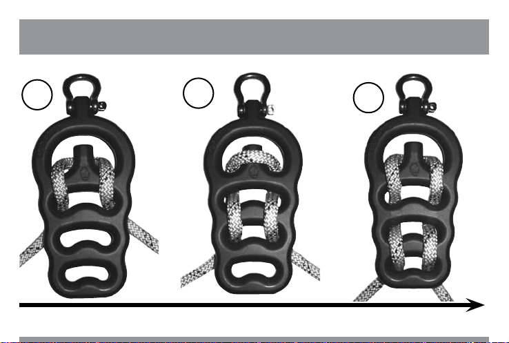
2) Settings of Gyb’Easy :
3 different positions exist (see page 4 pictures 5, 6 & 7) for a perfect adaptation to the mainsail area (up to 40 m²) and to the wind
conditions (i.e. sudden increase of wind from 3 to 6 bf). The more times the line passes over the openings of the brake, the more
the friction is increased and hence the brake efciency. As any boom brake, several tests may be useful before getting the right
adjustment. Once the correct setting is found, the strength of the brake can be increased by tensioning the Gyb’Flex. If there is
too much friction, remove one of the lower turns.
3) Limits of use, maintenance and precautions of use :
Limits of use: Gyb’Easy has been designed for a mainsail area under 40 m². CAUTION: good results are only guaranteed when
used with the specic Gyb’Flex line supplied. If replacement of the line becomes necessary, you must use the same type of line
(part # 7148). Please contact your local stockist.
In order to ensure your safety and perfect operation of the boom brake, it is recommended to regularly check the line for wear
and replace it after 5 years.
Maintenance: Gyb’Easy does not require any maintenance. However it is recommended to regularly rinse the brake and the line
with fresh water. During winter the system can easily be dismantled.
Precautions of use: CAUTION : even with a boom brake, it can still be necessary to reef the mainsail. The Gyb’Flex must be
used only for the purpose as described and not for any other applications (halyard, sheet…). Remember: the boom brake does
not substitute common sense and good seamanship !

6
II) INSTALLING THE BOOM BRAKE:
CAUTION : installation must always be symmetrical to the fore and aft axis of the boat.
1) Recommended installation with the line returning to the cockpit : see page 2 drawing 1 and 2
Step 1 : Installing the two blocks (B)
Attach the two blocks (B) as shown in drawing 1 (i.e: on the chainplates). To select the blocks, see table page 2.
Step 2 : Installing the boom brake (G)
Attach the boom brake to one saddle of the boom (behind the boom vang) as shown in drawing 1 and 2.
CAUTION : the length AG must be equal to lengths AB.
If it is not possible to attach the brake using a saddle, you can use a lashing (however the installation of a saddle is recommended).
Step 3 : Installing the Gyb’Flex line
Thread the Gyb’Flex line through a cockpit jammer or directly onto a winch. Then through both blocks (B) and back through the
opposite jammer of the cockpit or on the opposite winch. Make sure that nothing can prevent the free running of the line.
Step 4: Threading the line through the brake
Take the middle of the Gyb’Flex line between the two blocks B and thread it through the brake as shown on page 4 (pictures 5,
6 or 7).
Step 5 : Cut the line
Tension the line slighlty, make 3 turns on the winches and measure one meter before cutting the line to length.
2) Alternative installation with a single return to the cockpit. See page 3 drawings 3 and 4.
When the 1st recommended installation is not possible, it is still possible to install the boom brake as described below. This ins-
tallation requires more accurate settings and is less efcient for small mainsail areas.
In this particular case, the Gyb’Flex line does not return to the cockpit. The return line is a standard line (not delivered) which
allows you to adjust the tension from the cockpit.
Step 1 : Choice of the chainplates (F) for the Gyb’Flex line
Choose where to x the ends of the Gybe’Flex line i.e. the padeyes of lower shrouds (drawing 3).
Step 2 : Installing the blocks (C)
Attach the block C1 to one of the boom saddles behind the boom vang, then install the second block C2 at the mast foot (see
drawing 4). To select the blocks, see table page 3. CAUTION : in all cases the length AC1 must be similar to the lengths AF. If
the attachment to a saddle is not possible, use a lashing to attach the block to the boom (however the installation of a saddle is
recommended).
Step 3 : Installing the standard line
Attach the standard line to the shackle of the boom brake, pass it over the blocks C1 and C2 and then return it to the cockpit (on
a jammer or a winch). See drawing 4.
Step 4 : Positioning Gyb’Easy
With the standard line, position the boom brake so that the distance between the block C1 and the boom brake is around 30 cm.
See drawing 4.
Step 5 : Installing the Gyb’Flex line
Attach the Gyb’Flex on the port chainplate and pass the line through the boom brake as shown in picture 5. The length (d)
between the boom brake and the C1 block must be roughtly 30 cm (depending on the size of the boat) in order to have movement
to tension the Gyb’Flex line. It may take some experimenting to nd the correct length (d). See drawing 4.
Step 6 : Cutting the line
After several practice gybe operations, and once the right setting has been chosen, cut the extra length of the Gyb’Flex line and
keep it on board as spare line.
III) USE OF THE BRAKE:
> Choose the best setting adapted to your mainsail area and wind conditions (eg. sudden increase of wind from 3 to 6 bf).
> When sailing downwind : tension the Gyb’Flex (or the standard line) to allow the boom to gybe smoothly and controlled.
> When sailing up wind, release the line to allow easy tacking.
> It is highly recommended to test the various settings in different wind strengths to gauge the correct settings for your boat.
When the wind increases strongly, the settings may need to be changed eg. from position 1 to position 2 (see page 4 pictures
5,6 & 7).
> For your own safety : bring the boat to windward.
> Release the tension of the Gyb’Flex line (or the standard line).
> Remove the line from the boom brake.
> Pass the line over more openings to increase the friction.
IV) WARRANTY:
All Wichard products are warranted to be free of defects in materials or workmanship for ve (5) years from the date of purchase
by the original end-user. Excluded from this warranty are:
> Any product which has been improperly tted.
> Any product which has been improperly used or used in any application for which it was not intended.
> Any product which has been improperly maintained.
> Any product modied without a written approval from Wichard.
> Any damage being a consequence from alteration, ultraviolet light exposure or normal wear of products.

16
www.wichard.com
CONTACT
Wichard France
Hotline / support technique / SAV
33 rue de l’Etoile du matin
44600 St Nazaire
France
Tel: +33 (0) 2 51 76 00 35
Fax: +33 (0) 2 40 01 40 43
E-mail: [email protected]
Wichard Inc
20 West Canal street - Suite 524
Winooski - VT05404
USA
Tel: +1 401 683 5055
Fax: +1 802 655 4689
E-mail: [email protected]
Wichard Pacic Pty Ltd
PO Box 712 Edgecliff
NSW 2027
Australia
Tel: +61 2 9516 0677
Fax: +61 2 9516 0688
Free toll number: 1800 639 767
E-mail: [email protected]
W12FGB07
This manual suits for next models
1
Table of contents
Languages:
Other Wichard Boating Equipment manuals
Popular Boating Equipment manuals by other brands

Hobie
Hobie Mirage Compass instruction manual

SureShade
SureShade ATF Installation guides

RS SAILING
RS SAILING RS Venture Safety instructions

Lewmar
Lewmar S900 Owners installation, operation & servicing manual

Floe
Floe 510-27200-00 Assembly instructions and owner's manual

Seakeeper
Seakeeper 26 installation manual