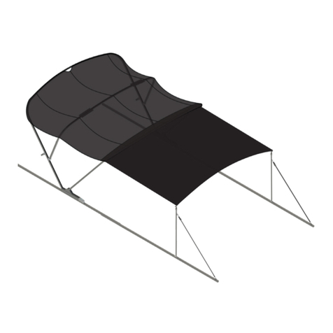
Lippert SureShade 2000 Series User manual

SureShade® 2000 Series
Forward Facing Power
Bimini
OEM INSTALLATION MANUAL

Rev: 12.11.23 Page 2 CCD-0007745
TABLE OF CONTENTS
Introduction 2
Safety 3
Resources Required 4
Preparation 4
Actuator Mounting Locations 4
Wiring the Forward Facing Bimini System 6
Post-installation Check 9
Notes 11
Introduction
The SureShade® 2000 Series Forward Facing Power Bimini is a pre-assembled electric actuator-driven
bimini top system powered by a 12V DC source. The forward facing shade can be easily operated by a
helm-mounted momentary switch.
Additional bimini system features include a mast light— all-around marine light—mounted to the bimini
frame that articulates within a 90-degree arc so the light can be adjusted to match the position of the boat's
bimini top and a courtesy light strip mounted along the forward bimini frame.
The SureShade® 2000 Series Forward Facing Power Bimini system weighs more than a typical power bimini
system and operates in a reverse fashion. The system's weight and design features place an emphasis on
having a robust watercraft design that can support the system's full range of operation. Therefore, it is the
responsibility of the OEM to ensure compatibility of the SureShade® 2000 Series Forward Facing Power
Bimini system to their watercraft.
For information on the assembly or individual components of this product, please visit:
https://support.lci1.com/sureshade-power-bimini/ .
Note: Images used in this document are for reference only when assembling, installing and/or operating
this product. Actual appearance of provided and/or purchased parts and assemblies may differ.
The 6 Amp auto-reset circuit breaker used on any Power Bimini System that does NOT use the touch-
sensitive controller MUST be protected by a 15 Amp auto-reset circuit breaker or a 30 Amp fuse.
The 6 Amp auto-reset circuit breaker provides protection for the Power Bimini System and NOT for
the entire craft's electrical wiring system. Do NOT use a replacement fuse less than 30 Amps. Circuit
breakers and fuses do NOT operate the same and are NOT interchangeable.

Rev: 12.11.23 Page 3 CCD-0007745
The "WARNING" symbol above is a sign that a procedure has a safety risk involved and may cause
death or serious personal injury and/or severe product or property damage if not performed safely
and within the parameters set forth in this manual.
Failure to follow instructions provided in this manual may result in death, serious personal injury
and/or severe product and property damage, including voiding of the component warranty.
The “CAUTION” symbol above is a sign that a safety risk is involved and may cause personal injury
and/or product or property damage if not safely adhered to and within the parameters set forth
in this manual.
Safety
Read and understand all instructions before installing or operating this product. Adhere to all safety labels.
This manual provides general instructions. Many variables can change the circumstances of the instructions,
i.e., the degree of difficulty, operation and ability of the individual performing the instructions. This
manual cannot begin to plot out instructions for every possibility, but provides the general instructions,
as necessary, for effectively interfacing with the device, product or system. Failure to correctly follow the
provided instructions may result in death, serious personal injury, severe product and/or property damage,
including voiding of the Lippert limited warranty.
Always wear eye protection when performing service, maintenance or installation procedures.
Other safety equipment to consider would be hearing protection, gloves and possibly a full face
shield, depending on the nature of the task.
All electrical wiring harnesses shall be loomed and secured to prevent possible damage and
installed in accordance with the latest ABYC (American Boat and Yacht Council) electrical standards.
Do NOT fully open the bimini frame without the canvas top installed when testing product for
proper operation. Opening the bimini frame without the canvas top installed will result in severe
product damage. Only fully open the bimini frame with the canvas top installed.
Moving parts can pinch, cut or crush. Keep clear and use caution.
Only open the bimini top indoors when testing for proper installation. Opening the bimini top
outdoors subjects the system to possible strong winds that could result in severe product damage.
Only open the bimini top indoors when testing product for proper operation.

Rev: 12.11.23 Page 4 CCD-0007745
Fig. 1
Fig. 2
Resources Required
• 1-2 persons, depending on task
• Cordless or electric drill or screw gun
• 3/8" drill bit
• 9/16" wrench
• Tape measure
• Pencil
Preparation
Actuator Mounting Locations
When installing the complete forward facing bimini system onto the boat's railing, make sure:
• The actuators are mounted square, level and plum to one another.
• No actuator is mounted more than 1/4" ahead of the other.
• Wires are run in a manner that will prevent them from being pinched under the actuators. If necessary,
provide wire harness access holes where needed.
• Actuator minimum voltage is 11V DC when under load.
The forward facing bimini system should be in its Stowed position with the protective boot installed(Fig.1).
1. With assistance, place the forward facing bimini system's actuators onto the boat's frame/
railing(Fig.2).
Protective
Boot
Forward Facing Bimini System in its Stowed Position
Actuator
Railing

Rev: 12.11.23 Page 5 CCD-0007745
Some boat frames/railings may be pre-wired. Drilling through a pre-wired frame/railing may nick
or cut electrical wires, resulting in a damaged and/or unusable electrical harness. Carefully drill
through one surface and inspect for wiring.
A. If the boat's frame is pre-drilled, go to step 2 to continue installation.
B. If the boat's frame is NOT pre-drilled, do as follows:
I. Move the port and starboard actuator assemblies forward and aft until the actuators are
in-line with each other (Fig. 3).
II. Make sure the actuators are mounted square, level and plum to one another.
III. Make sure no actuator is mounted more than 1/4" ahead of the other (Fig. 3).
IV. After properly positioning each actuator assembly, use a pencil to make a line around each of
the four mounting studs.
V. Lift the forward facing bimini system off of the boat and set aside.
Fig. 3
VI. At each pencil mark (4 places), find the center of the railing's width then drill a through-hole
using a 3/8" bit. These holes need to go all the way through the railingtube.
Note: Use care when drilling through a pre-wired boat frame/railing. If necessary, drill through one wall of
the tube, then inspect for wires to make sure they are out of the way.
VII. With assistance, place the bimini system back onto the boat.
2. Set the actuator mounting studs into the drilled holes of the railing (Fig. 4).
3. Secure the bimini system in place with 5/16" split lock washers (Fig. 4A) and 5/16"-18 acorn nuts
(Fig.4B) fourplaces.
4. Use a 9/16" wrench to tighten the acorn nuts.
1/4" Max
Offset
Starboard
Actuator
Port
Actuator
Actuators
Aligned
Parallel

Rev: 12.11.23 Page 6 CCD-0007745
Wiring the Forward Facing Bimini System
The SureShade 2000 Series Forward Facing Power Bimini actuators, mast light and the light strip MUST be
wired to a control switch independent of each other. Do NOT combine any of these wire harnesses prior to
their connection to a dedicated control.
Connecting the Port and Starboard Actuators
1. Locate the dedicated momentary switch for the forward facing bimini system.
2. Connect the white wire from the actuator harness (Fig. 5A) to one side of the switch.
3. Connect the dark blue wire from the actuator (Fig. 5B) to the other side of the switch.
4. Make sure the switch is properly connected to the positive and negative switch leads then to the
circuit protection as shown in the Wiring Diagram (Fig. 5) and then to the watercraft's power source.
Fig. 4
Fig. 5
A
B
White
Dark Blue
Switch
A B
6 Amp short stop breaker,
Bussman #121A06-A2M-HD.
Battery
Positive (+)
Battery
Ground (–)
Circuit
Protection

Rev: 12.11.23 Page 7 CCD-0007745
Connecting the Mast Light
1. Locate the dedicated switch for the mast light.
2. From the mast light, connect the gray wire to one side of the switch and the black wire to
ground(Fig.6).
3. Make sure the switch is properly connected to the positive and then to the circuit protection as shown
in the Wiring Diagram (Fig. 5).
Fig. 6
Watercraft
Power Source
Helm Switch
Mast Light
Black Wire
& Gray Wire

Rev: 12.11.23 Page 8 CCD-0007745
Fig. 7
Connecting the LED Courtesy Light Strip
1. Locate the dedicated switch for decorative lighting.
2. From the light strip, connect the white wire to one side of the switch and the black wire to
ground(Fig.7).
3. Make sure the switch is properly connected to the positive battery lead and to the circuit protection as
shown in the Wiring Diagram (Fig. 5).
LED Strip
Light
Helm Switch
Watercraft
Power Source

Rev: 12.11.23 Page 9 CCD-0007745
Post-installation Check
1. Make sure actuators are securely fastened to the railings.
2. Make sure all actuator wires are loomed and secured in-place.
3. If necessary, remove the protective boot from the forward facing bimini.
4. Turn On the watercraft's power.
A. Turn On and Off the Interior or ACC lighting switch that controls the mast light. Verify that the
light turns On and Off as directed.
B. Turn On and Off the Interior or ACC lighting switch that controls the LED light strip. Verify that the
light strip turns On and Off as directed.
C. Make sure all lights are turned Off after testing.
D. Test the actuators.
I. Press and hold the forward facing bimini helm switch until the bimini fully extends into the
Open Position and stops itself (Fig.8). Release switch.
II. Press and hold the forward facing bimini helm switch until the bimini fully retracts into the
Stowed Position and stops itself (Fig. 9). Release switch.
Do NOT power actuators to the full open position without canvas installed. Damage may occur.
Before operating the power bimini top, thoroughly inspect the area around the entire bimini
assembly. Verify that nobody is in an area that will interfere with the motion of the bimini assembly.
Serious injury could result.
Only open the bimini top indoors when testing for proper installation. Opening the bimini top
outdoors subjects the system to possible strong winds that could result in severe product damage.
Only open the bimini top indoors when testing product for proper operation.
Fig. 8
Open Position
Stowed Position
Fig. 9

Rev: 12.11.23 Page 10 CCD-0007745
Fig. 10
Radar Position
Boot
III. Install the boot over the bimini top then press and hold the forward facing bimini helm switch
until the bimini is in the Radar Position and stops itself (Fig. 10). Release switch.
Note: The canvas boot MUST be installed to achieve Radar Position. The bimini top will NOT stop automatically in
the Radar Position without the boot installed.
5. Make final adjustments as necessary.
6. Put the forward facing bimini in its Stowed Position (Fig. 9).
7. Turn Off the watercraft's power.

Rev: 12.11.23 Page 11 CCD-0007745
Notes

The contents of this manual are proprietary and copyright protected by Lippert. Lippert prohibits the copying or
dissemination of portions of this manual unless prior written consent from an authorized Lippert representative
has been provided. Any unauthorized use shall void any applicable warranty. The information contained in this
manual is subject to change without notice and at the sole discretion of Lippert. Revised editions are available
for free download from lippert.com.
Please recycle all obsolete materials.
For all concerns or questions, please contact Lippert
Table of contents
Other Lippert Boating Equipment manuals
Popular Boating Equipment manuals by other brands

Side-Power
Side-Power MIDI201 Installation and user manual

Patriot Docks
Patriot Docks Manual Pontoon Assembly instructions

Floe
Floe V-2000 Assembly instructions

PupGear
PupGear Original doggydocks installation instructions

Samyung
Samyung SRG-315DN user manual

Volvo Penta
Volvo Penta Glass Cockpit owner's manual