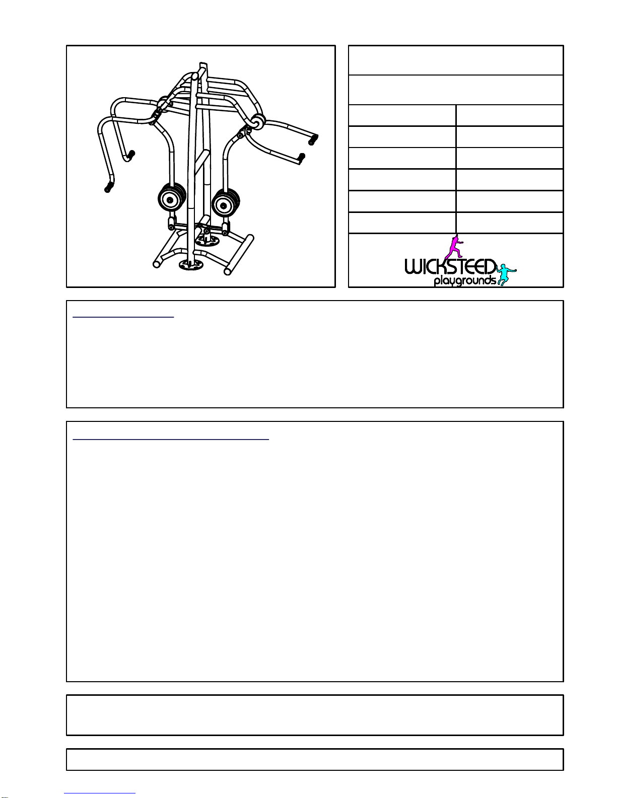
Wicksteed 6210-059 User manual

SPECIFICATION
INSTALLATION INSTRUCTIONS
Note
Note
PROD. CODE
SIZE
AGE RANGE
F/ FALL HEIGHT
HEAVIEST PART
TOTAL WEIGHT
Fitness Legacy Zone
6210-059
14 to Adult
<600mm
Approx 266Kg
Approx 311Kg
6210-059
Page 1 of 15
1135x2260x2400mm
Ensure all installation aids are removed before first use.
Polyester powder paint to EN 13438:2005
Standard fixings to BS 3692:2001 and
BS 4190:2001
Non-standard fixings are anti-vandal and
corrosion resistant
Inc Chest Press & Inc Pull Down
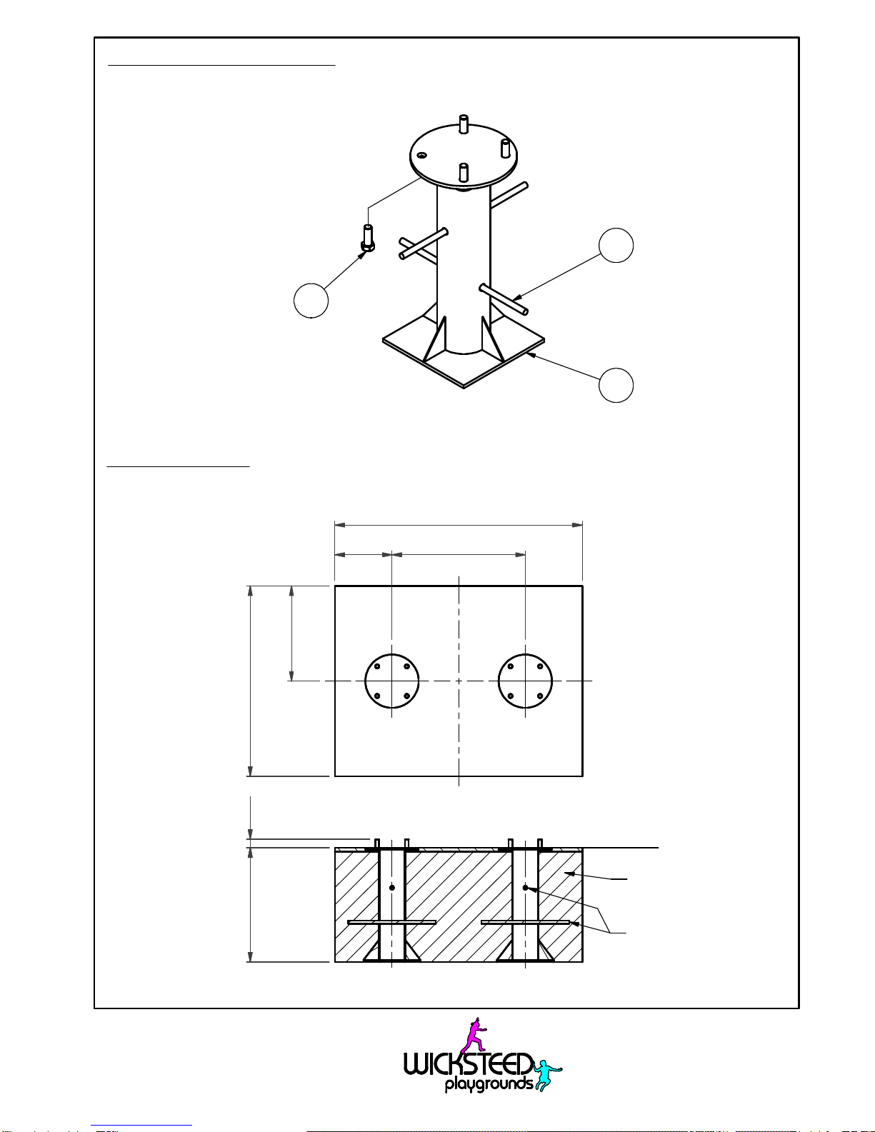
Use Installation Aid (3720-184) for Below Ground Fixing.
1 Read installation instructions thoroughly before commencing installation of unit.
2 Excavate one hole 1300 x 1000 x 600 deep - see page 2.
3 Position and assemble the below ground fixing with spragging irons (see page 2) centrally in the
excavated hole so the eight bolts are pointing upwards ensuring that the top plate is flush with the
finished surface level.
4 Check alignment of bolts and backfill the holes with concrete (0.76 cu Metres) (4 parts gravel, 2 parts
sand & 1 part cement) ensuring the below ground fixing is perpendicular to the finished surface level.
5 Allow the concrete to set for 48 hours.
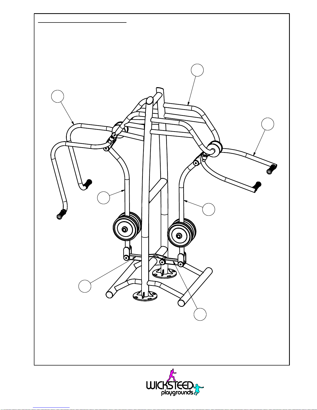
6 Position the unit on the below ground fixings and fit using one M20 washer, one M20 spring washer
and one M20 nut per bolt as shown on page 3. Ensure unit is perpendicular to the ground surface.
Ensure all moving parts move freely without obstruction. Centre punch thread in two places on all
eight M20 Bolts and then fit nut cap (see page 3).
Steel plate to EN 10025
Steel CHS to EN 10219
Steel RHS to EN 10219
Welding to EN ISO 14341:2011

6210-059
Page 2 of 15
FSL
FSL = Finished Surface Level
Below Ground Fixing Details
(2 off)
Foundation Detail
(Care must be taken in abnormal conditions)
TYP
600 (45)
Spragging Iron
300
4
3
2
700 Ctrs
1300
1000
500
Concrete

6210-059
Page 3 of 15
Chest Press & Pull Down Unit to Below Ground Fixing Details
Centre punch thread in two places
on all eight M20 Bolts
8
7
6
5

6210-059
Page 4 of 15
Minimum and Training Spaces
3410
(5320)
26602660
1705
700700
R1500
R1000
Training Space
Training Space
2500 Min
(2259)
Minimum Space

6210-059
Page 5 of 15
Safety Surfacing
Wetpour
17.0 Sq. Metres 20mm Wetpour
15.5 Linear Metres Wetpour Edging
Grass Mats
(1500 x 1000mm)
16 off Total
Safety Tiles
(1000 x 1000mm)
19.0 Sq. Metres
40mm Thickness
18.0 Linear Metres of Tile Edging
5420
3500
1750
6000
3000
4000
2000
5500
3500
27102710
1750
2730
R1550

6210-059
Page 6 of 15
Fixing Details for Maintenance
Main Assembly
1.1
1.3
1.2
1.5
1.6
1.4
1.4

6210-059
Page 7 of 15
Fixing Details for Maintenance
Chest Press Handle Assembly to Main Frame Assembly
*= For use with Beige/Green
Standard Colour Panel
1.9
1.13
1.10
1.11
1.13 1.10 1.11
1.2.5 1.2.4 1.2.10
1.2.9 1.2.13
1.2.7
1.2.2
1.2.3
1.2.5
1.2.4
1.2.10
1.2.12
1.2.21.2.3
1.2.1
1.2.61.2.14
1.2.15 *
1.2.8
1.2.11

6210-059
Page 8 of 15
Fixing Details for Maintenance
Chest Press Lever Assembly to Handle Assembly and Main Frame
see sheet 9
1.11
1.13
1.10
1.12
1.10
1.11
1.11
1.10
1.13
1.8
1.7
1.11 1.10
1.12
1.4.1
1.11
1.10
1.12
1.7
1.12
1.10
1.11
1.4.2
1.4.3
1.4.3
1.4.2

6210-059
Page 9 of 15
Fixing Details for Maintenance
Chest Press Lever Assembly
*= For use with Beige/Green
Standard Colour Panel
1.5.4
1.5.4
1.5.4
1.5.4
1.5.1
1.5.3
1.5.2
1.5.2
1.5.3
1.5.8
1.5.6
1.5.7
1.5.11
1.5.12 *
1.5.9
1.5.10
1.5.5
1.5.8
1.5.6
1.5.7
1.5.5
1.5.10
1.5.9
1.5.11
1.5.12 *

6210-048
Page 10 of 15
Fixing Details for Maintenance
Pull Down Handle Assembly to Main Frame Assembly
*= For use with Beige/Green
Standard Colour Panel
1.3.6
1.3.11 1.3.8 1.3.14
1.3.15 *
1.3.2 1.3.3
1.3.3
1.3.2
1.3.7 1.3.13
1.11 1.10 1.13
1.9 1.13 1.10
1.11
1.3.9 1.3.10 1.3.4
1.3.5
1.3.5 1.3.4 1.3.10
1.3.12

6210-059
Page 11 of 15
Fixing Details for Maintenance
Pull Down Lever Assembly to Handle Assembly and Main Frame
see
sheet 12
1.7
1.12
1.10
1.11
1.11
1.10
1.13
1.8
1.12
1.10 1.11
1.13
1.10 1.11
1.11
1.10
1.12
1.7
1.12
1.11
1.10
1.4.1
1.4.3
1.4.2
1.4.2
1.4.3

6210-059
Page 12 of 15
Fixing Details for Maintenance
Pull Down Lever Assembly
*= For use with Beige/Green
Standard Colour Panel
1.6.3
1.6.2
1.6.2
1.6.3
1.6.1
1.6.4
1.6.4
1.6.4
1.6.4
1.6.9
1.6.10
1.6.5
1.6.11 1.6.12 *
1.6.7
1.6.6
1.6.8
1.6.8
1.6.6
1.6.7
1.6.5
1.6.10
1.6.9
1.6.11
1.6.12 *

Parts List
DESCRIPTION
PART NUMBER
QTY
ITEM
Inc Chest Press & Inc Pull Down Assembly5104-021
11
Inclusive Combi Frame W.A.
4202-630
11.1
Inclusive Chest Press Handle Assembly
4202-247
1
1.2
Handle W.A.4202-248
1
1.2.1
BALL BEARING Ø52 x Ø25 x 15
2541-10521.2.2
Internal Circlip Ø52mm
2441-01221.2.3
Small Buffer (Top)
2906-02321.2.4
Small Buffer (Bottom)
2906-02421.2.5
Handle
3730-16121.2.6
Aluminium Finial
3711-01821.2.7
M8 x 30 Pent Button Head2176-15321.2.8
M8 x 50 SKT CAP HD SCREW2171-012
1
1.2.9
M8 Washer
2215-50721.2.10
M8 NORD LOCK WASHER2212-21421.2.11
M8 Binx Nut2191-009
1
1.2.12
M10 x 50 Pent Button Head
2176-12921.2.13
Black Poepplemann Cap
2611-031_Cap21.2.14
Green Poepplemann Cap
2611-033_Cap21.2.15
Pull Down Handle Assembly
4202-025
1
1.3
Handle W.A.
4202-026
1
1.3.1
BALL BEARING Ø52 x Ø25 x 15
2541-10521.3.2
Internal Circlip Ø52mm
2441-01221.3.3
Small Buffer (Top)
2906-02321.3.4
Small Buffer (Bottom)
2906-02421.3.5
Handle
3730-16121.3.6
Aluminium Finial
3711-01821.3.7
M8 x 30 Pent Button Head
2176-15321.3.8
M8 x 50 SKT CAP HD SCREW2171-01211.3.9
M8 Washer
2215-50721.3.10
M8 NORD LOCK WASHER2212-21421.3.11
M8 Binx Nut
2191-00911.3.12
M10 x 50 Pent Button Head
2176-12921.3.13
Black Poepplemann Cap
2611-031_Cap21.3.14
Green Poepplemann Cap2611-033_Cap21.3.15
6210-059
Page 13 of 15
Parts List Continued on Page 14

Parts List
DESCRIPTION
PART NUMBER
QTY
ITEM
Lever Assembly
4202-2192
1.4
Lever W.A.
4202-220
11.4.1
BALL BEARING Ø42 x Ø20 x 12
2541-10641.4.2
Internal Circlip Ø42mm
2441-011
4
1.4.3
Lever Assembly4202-245
11.5
Lever W.A.4202-24611.5.1
BALL BEARING Ø52 x Ø25 x 15
2541-10521.5.2
Internal Circlip Ø52mm
2441-01221.5.3
10Kg Weight
3711-07641.5.4
End Cap
3030-30921.5.5
Weight Washer
3292-15221.5.6
DIA 6 x 12 LG SELLOK PIN2223-0212
1.5.7
DIA 1/8" x 3/4" LG SELLOK PIN
2223-01021.5.8
M10 x 30 LG HEX HD SCREW2175-11621.5.9
M10 NORD LOCK WASHER2212-21221.5.10
Black Poepplemann Cap
2611-031_Cap21.5.11
Green Poepplemann Cap
2611-033_Cap21.5.12
Lever Assembly
4202-217
1
1.6
Lever W.A.
4202-218
1
1.6.1
BALL BEARING Ø52 x Ø25 x 15
2541-10521.6.2
Internal Circlip Ø52mm
2441-01221.6.3
10Kg Weight
3711-076
41.6.4
End Cap
3030-30921.6.5
Weight Washer
3292-15221.6.6
DIA 6 x 12 LG SELLOK PIN2223-02121.6.7
DIA 1/8" x 3/4" LG SELLOK PIN
2223-01021.6.8
M10 x 30 LG HEX HD SCREW2175-11621.6.9
M10 NORD LOCK WASHER2212-21221.6.10
Black Poepplemann Cap
2611-031_Cap21.6.11
Green Poepplemann Cap
2611-033_Cap21.6.12
Spindle
3033-149
41.7
Spindle
3033-15021.8
Spindle
3033-15121.9
6210-059
Page 14 of 15
Parts List Continued on Page 15

REV
ECN
SIG.
DATE:
COMPILED
DATE:
6210-059
Page 15 of 15
MC
06/01/17
Parts List
DESCRIPTION
PART NUMBER
QTY
ITEM
Bearing Cover3730-163161.10
M8 x 25 Pent Button Head2176-152
161.11
External Circlip Ø20mm
2441-01581.12
External Circlip Ø25mm
2441-01481.13
BELOW GROUND FIXING5071-03122
460mm Spragging Iron3030-31043
M20 x 55 HT HEX HD SCREW2175-1818
4
M20 WASHER 2mm THK2215-5128
5
20mm SPRING WASHER2212-206
8
6
M20 nyloc nut
2192-0128
7
M20 Nut Cap2613-02188
06/01/17
MC
Minor
0
Table of contents
Other Wicksteed Fitness Equipment manuals
Popular Fitness Equipment manuals by other brands

Monark
Monark 927 E Cardio Care manual

Slendertone
Slendertone Abs instruction manual

New Image
New Image CYCLONE X3 Assembly and user's guide

PRx Performance
PRx Performance Profile PRO installation instructions

THERA-Trainer
THERA-Trainer MOBI operation instruction

Focusmaster
Focusmaster G-1000 Owner's handbook