Widearea AEP-RACK-L User manual

Chengdu Widearea Telecommunication Technology Co., Ltd
Add: 2nd,3rd East Round Longtan Industry Garden 10#,Chengdu, Sichuan, China
Tel: (86)28 84207501 (86)28 84207506 Fax: (86)28 84209696
ADSLLoop Extender Power Supply
AEP-RACK-L & AEP-C2PL
Installation Manual
Version: 7.0
Please read this
document carefully
before installation!

ADSL Loop Extender Power Supply Installation Manual Page 1
This publication may not be reproduced in whole or in part without the express
written permission of Widearea.
Preface
This manual provides information on how to use the product. To
make the best use of the product, read this manual thoroughly
before use and keep this manual handy for ease of reference.
The contents of this document may be updated in the future,
without prior notice.
This booklet was created with thorough attention to the content.
If, however, you have a question, spot an error, or find a
description lacking, please refer to the end of this booklet for
information on how to contact us.
All brand names and trademarks are the property of their
respective owners.

ADSL Loop Extender Power Supply Installation Manual Page 2
This publication may not be reproduced in whole or in part without the express
written permission of Widearea.
Contents
1. General Description..................................................................... 3
2. Technical Specifications.............................................................. 4
3. Physical Structure........................................................................ 4
4. Application.................................................................................. 5
5. Installation Procedure.................................................................. 6
6. Troubleshooting........................................................................... 8

ADSL Loop Extender Power Supply Installation Manual Page 3
This publication may not be reproduced in whole or in part without the express
written permission of Widearea.
1. General Description
ADSL Loop Extender can extend the coverage of ADSL access. It will provide
systems with higher performance-to-cost ratio, improve the equipment utilization
rate and optimize the network. This product will allow you to double the number
of subscribers that you can reach while offering more consistent high bandwidth
services to your existing customers.
ADSL Loop Extender is an active element installed in the outside loop plant. It
operates as an amplifier and equalizes the signal. Generally, it is span-powered.
You can use the ADSL Loop Extender Power Supply to provide the span-power.
Figure 1 AEP-RACK-L and the power card AEP-C2PL
AEP-RACK-L is a rack for AEP-C2PL embedded. One rack can be
inserted into 14 cards.
AEP-C2PL is two outlets power supply for line power supply ADSL Loop
Extender AER800-xPL. Each outlet can supply for one port line power
Extender. No additional copper pairs are required to supply power.
Benefits
Economize the copper pairs for no additional pairs are needed for power.
Centralize and regularize power supply, make the CO clean

ADSL Loop Extender Power Supply Installation Manual Page 4
This publication may not be reproduced in whole or in part without the express
written permission of Widearea.
Comprehensive over-voltage protection.
Easy to install, deploy and maintain
2. Technical Specifications
Table 1 –Technical Specifications of AEP-RACK-L& AEP-C2PL
Operating Environment
Temperature
-10℃~+45℃
Relative Humidity
5%~95%
(Non-condensing)
Input Voltage
DC -48V(-36V~-72V)
Output Voltage
DC 155V per port
Output Current
Less than 50mA
Dimension of RACK
485 mm(L)×310mm(W)×133mm(H)
3. Physical Structure
AEP-RACK-L
Figure 2 The back panel of AEP-RACK-L
In figure 2, you can input DC48V through the 2×3 cords “DC48V-I”. The
“DC48V-II”is only used in testing in the factory. At the middle of the 2×3
cords, there is a 2-core ground terminal. Cooper-core wire with no less

ADSL Loop Extender Power Supply Installation Manual Page 5
This publication may not be reproduced in whole or in part without the express
written permission of Widearea.
than 2.5mm2section is required as ground wire. When the card is AEP-C2PL,
you can get 2х155V from “A2B2” and “A4B4”outlet, supply power for the
signal line power Extender.
Figure 3 The panel of AEP-C2PL
In figure 4, “POWER”indicates the status of the equipment. After power
supply connected, press the button “K”, and the corresponding “POWER”
indicator should be on. Flashing indicator indicates short circuits or
over-current alarm condition. “OFF-HOOK” is on indicates the telephone
is picking, the light will be on. “Sequence” is on indicates that line
sequence inputted incorrectly, please exchange “A1” and “B1”or “A3”
and “B3” line sequence, to input correctly, the light will be off.
4. Application
POTS
ADSL
Mode
m
CPE
L2
ADSL+PO
TS
ADS
L
L1
Power
Supply
ADSL+POT
S
AEP-RACK
AEP-C2PL
switch
POT
S
CO
ADSL
Loop
Extender
splitter
DSLAM

ADSL Loop Extender Power Supply Installation Manual Page 6
This publication may not be reproduced in whole or in part without the express
written permission of Widearea.
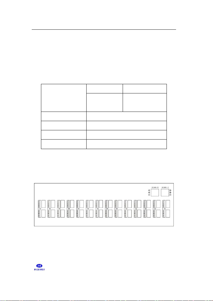
Figure 4 AEP-C2PLApplication Diagram
L1: The signal twist pair connecting power supply to Extender
L2: The signal twist pair connectingADSL Loop Extender to Modem.
Note: Signal line power supply Extender with remote power supply
AEP-C2PL from central office, no additional copper pair required to
power the Extender.
5. Installation Procedure
1. Unpack
Unpack equipment carefully; check the completeness against the purchase order.
Notify the supplier if any item are missing.
Note: Save packing material. All equipment returned must be packed in
the original packing material.
Inspect equipment for shipping damage, including bent or loose hardware, and
broken connectors.
If equipment was damaged in transit, contact the supplier.
2. Install the power supply
Attention: ADSL Loop Extender’s power supply should NOT be turned on
until the Extender installation is finished. When the power supply wire is
active, wires carry DC 155V. Do not touch wire A and wire B simultaneously, or
allow wires to contact anything!
⑴Fix the AEP-RACK-L in the 19’cabinet and ground the AEP-RACK-L.
Attention: Cooper-core wire with no less than 2.5mm2 section is required as
ground wire. One end of the wire should be connected to the ground terminal

ADSL Loop Extender Power Supply Installation Manual Page 7
This publication may not be reproduced in whole or in part without the express
written permission of Widearea.
of the AEP-RACK-L, the other end of the wire should be connected to a good
ground point.
⑵Insert Power Supply card AEP-C2PL into AEP-RACK-L.
⑶Connect the power supply cable
No additional copper pair is required for power. Choose the signal line from the
DSLAM/Switch, connect it to the “A1B1”or “A3B3” terminal of AEP-C2PL.
Choose the signal line linked to the extender; connect it to “A2B2”or “A4B4”
terminal of AEP-C2PL.
Table 2 the Description of the buttons, indicators and outlets
Buttons, Indicators and Outlets
description
J
K1
A1B1
The first signal line input, connect the twist pair from
DSLAM.
A2B2
The first signal and Power supply output, connect the
twist pair to Extender.
K2
A1B1
The second signal line input, connect the twist pair from
DSLAM.
A2B2
The second signal and Power supply output, connect the
twist pair to Extender.
Power
Power indicator.
OFF-HOOK
The status of telephone indicator.
Sequence
The signal line sequence inputted indicator.
Note: 1. In this table, the “J”indicates any of the outlet “J1~J14”“POWER”
indicators should be on. Flashing indicator indicates short circuits or
over-current alarm condition.
Attention: Do not connect the cable linked to the Extender to the “A1B1”or

ADSL Loop Extender Power Supply Installation Manual Page 8
This publication may not be reproduced in whole or in part without the express
written permission of Widearea.
“A3B3” terminal, and do not connect the cable of the DSLAM /Switch to the
“A2B2” or “A4B4” terminal, or else, the equipment would be damaged.
⑷Connect power cord(do not apply power yet)
Connect the DC48V power source to the RACK with good connection. Please
connect the cord according to the sign of polarization.
Attention: ADSL Loop Extender’s power supply should NOT be turned on
until the Loop Extender installation is finished.
6. Troubleshooting
Table 3 AEP-C2PL Troubleshooting
Problem Description
Possible Reason
Suggested Resolution
“Power”is off
Power cord is not correctly
connected.
Check power cord
connection.
Power switch is not open
Press the power switch
“sequence”is on
The line sequence
connected incorrectly
Exchange line sequence of
“A1B1”or “A3B3”.
Output is OK but ADSL
extender does not work.
Signal cable connection is
error or short
Please refer to the
installation manual of
ADSL Loop Extender.
This manual suits for next models
1
Table of contents
Other Widearea Power Supply manuals