Wieland gesis FLEX-REG4 User manual

Montageanleitung (Original)
Installation Instructions (Translation based on Original Documentation)
gesis FLEX-REG4 (V/D/DV)
Systemgehäuse für Reiheneinbaugeräte (4 Teilungseinheiten)/
System housing for rail-mounted devices (4 split modules)
83.020.066x.0
Wieland Electric GmbH
Brennerstraße 10-14
96052 Bamberg
Tel.: +49 (951) 9324-0
Fax: +49 (951) 9324-198
Internet: www.wieland-electric.com
Email: info@wieland-electric.com
Doc. # BA000897 - 02/2014 (Rev. A) gesis FLEX-REG4 DE/EN 1
GEFAHR
•Nur Elektrofachkräfte dürfen dieses Gerät installieren und in Betrieb nehmen. Vor
Ausführung müssen sie diese Anleitung gelesen und verstanden haben.
•Gerät nur in spannungsfreiem Zustand öffnen, anschließen oder trennen.
•Die interne Klemme X1 (siehe Rückseite, Abbildung 1) darf nur für den Abgriff der Netz-
spannung genutzt werden. Das Einspeisen von Netzspannung über die Klemme X1 ist
nicht zulässig.
•Beim Einbau von Reiheneinbaugeräten haftet der Kunde selbst für den gefahrlosen Betrieb
und die Einhaltung der gesetzlichen Vorschriften.
•Die einschlägigen Normen, Richtlinien, Vorschriften und Bestimmungen des jeweiligen
Landes sind zu beachten.
Das REG-Modul ist systemkonform zum flachen, auf Tragschiene montierbaren Modulsystem
gesis FLEX. Es kann Reiheneinbaugeräte nach DIN 43880 mit 4 Teilungseinheiten (TE) auf-
nehmen. Vom vorgeschalteten Modul wird die Netz- und Busversorgung zum nächsten Modul
weitergeleitet. Das Netz kann intern über einen GST15 Anschluss abgegriffen werden.
Das Modul ist unbearbeitet (83.020.0600.0), mit Kabeleinführungen (83.020.0661.0,
83.020.0663) oder Klappdeckel erhältlich (83.020.0662, 83.020.0663).
Bestückung
Schritte siehe Rückseite
1. REG-Geräte auf Tragschiene im Gehäuseunterteil setzen. Abbildung 3
2. Modul mit Klappdeckel: Klappdeckel montieren. Abbildung 4
3. Bei Kabeleinführung: Kabel abisolieren, ablängen und durch die Kabe-
leinführung führen.
Abbildung 5
4. Verdrahtung der REG-Geräte vornehmen.
5. Gehäuseoberteil auf Gehäuseunterteil setzen und mit hörbarem Klick
einrasten.
Abbildung 6
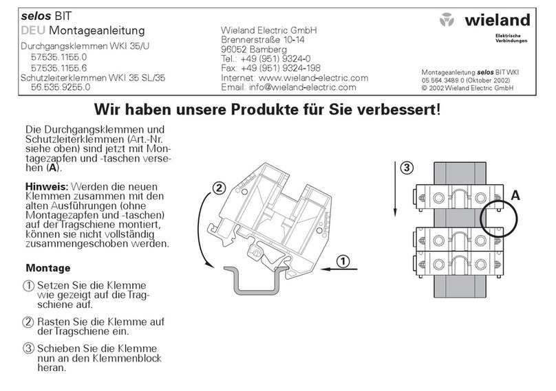
Montage (siehe Rückseite, Abbildung 7)
Schritt 1: Module Stecken
1.1 Endkappe links auf das erste Modul setzen und einrasten.
1.2 Module in gewünschter Reihenfolge mit hörbarem Klick einrasten.
1.3 Endkappe auf letztes Modul rechts aufsetzen und einrasten.
Schritt 2: Optional: Befestigung auf Tragschiene oder Montagerahmen
2.1 An jedem Modul mit Schraubendreher den Rastfuß nach oben ziehen.
2.2 Module auf Tragschiene aufsetzen.
2.3 An jedem Modul mit Schraubendreher den Rastfuß nach unten drücken.
Die Module sind auf der Tragschiene befestigt.
Schritt 3: Kabel stecken und sichern
3.1 Kabel an allen weiteren Modulen stecken (Siehe: Montageanleitungen).
Wichtig: Festen Sitz aller Steckverbindungen und Verschraubungen sicherstellen.
3.2 Bei Montagerahmen: Leitungen mit Kabelbindern am Montagerahmen befestigen.
Demontage für Wartung/Reparatur (siehe Rückseite, Abbildung 2)
Schritte
1. Schraubendreher an Rasthaken einführen.
2. Rasthaken mit der Klinge zurückdrücken.
3. Rasthaken durch leichtes Ziehen am Gehäuseoberteil aus der Arretierung lösen.
4. Schritte 1 bis 3 für die restlichen 5 Rasthaken durchführen.
5. Gehäuseoberteil abnehmen.
Wichtig: Zur Entnahme der Platine Kabelverschraubungen lösen.
Technische Daten
Netzdurchführung
Bemessungsspannung
1-phasig oder 3-phasig
230 V / 400 VAC, -15 % / +10 %, 50/60 Hz (GST15i5)
Bemessungsstrom 16 A je Außenleiter
Empfohlene Absicherung 1-poliger oder 3-poliger Leitungsschutzschalter B16A
Umweltbedingungen
Einsatzbereich Innenräume und trockene Räume, wettergeschützt
Klimabeständigkeit Klasse 3K5 (EN 50491-2)
Umgebungstemperatur -5 °C bis +45 °C
Lagertemperatur -25 °C bis +75 °C
Montageart Decken-, Boden-, Wandmontage, feste Installation, Aufputz, auf
ebene Fläche, Tragschiene TH35, Montagerahmen
Gehäuse
Material Kunststoff, halogenfrei
Farbe Lichtgrau, ähnlich RAL 7035 / Schwarz, ähnlich RAL 9005
Brandverhalten
Brandlast
Abmessungen (B, H, L)
UL94 V-2
ca. 2 kWh
95 mm, 149 mm, 44 mm
Elektrische Sicherheit
Schutzklasse I
Schutzart IP20 (nach EN 60529)
Verschmutzungsgrad 2
Überspannungskategorie III
Handbuch
mit detaillierten Informationen zu Programmierung, Inbetriebnahme und
Wartung:
•Dokumentnummer: BA000903
•Download über QR-Code oder:
http://eshop.wieland-electric.com/product/83.020.0660.0
http://eshop.wieland-electric.com/product/83.020.0661.0
http://eshop.wieland-electric.com/product/83.020.0662.0
http://eshop.wieland-electric.com/product/83.020.0663.0
DANGER
•Only trained electricians may install and commission this device. They must have read and
understood this instruction manual before they carry out installation.
•Only open, connect or disconnect the device if it has been de-energised.
•The internal X1 terminal (see back page, Figure 1) may only be used for picking up the
mains supply. Feeding in the mains supply via the X1 terminal is not permitted.
•When installing rail-mounted devices, the customer assumes liability himself for safe
operation and observing the statutory regulations.
•The relevant standards, directives, regulations and provisions of the particular country are
to be observed.
The REG module is system-compliant with the flat gesis FLEX module system, which can be
mounted on the carrier rail. It can accept rail-mounted devices in accordance with DIN 43880
with 4 split modules. The mains and bus supply is transferred from the upstream module to
the next module. The mains can be picked up internally via a GST 15 connection.
The module is available as unmachined (83.020.0600.0), with cable entries (83.020.0661.0,
83.020.0663) or with a hinged cover (83.020.0662, 83.020.0663).
Mounting
Steps See back page
1. Place the REG devices on the carrier rail in the lower part of the housing Figure 3
2. Module with hinged cover: Fit the hinged cover. Figure 4
3. In the case of cable entry: Remove the insulation, cut to length and feed
through the cable entry.
Figure 5
4. Carry out the wiring of the REG devices.
5. Place the upper part of the housing on the lower part and latch it into
place with an audible click.
Figure 6
Installation (see back page, Figure 7)
Step 1: Plugging in modules
1.1 Place the end cap at the left onto the first module and latch it into place.
1.2 Latch the modules in the desired sequence into place with an audible click.
1.3 Place the end cap on the last module on the right and latch it into place.
Step 2: Optional: Fastening on carrier rail or mounting frame
2.1 Pull the resting foot on every module upwards with a screwdriver.
2.2 Place the modules on the carrier rail.
2.3 Press the resting foot on every module downwards with a screwdriver.
The modules are now fastened on the carrier rail.
Step 3: Plugging in cables and securing them
3.1 Plug the cables into all the other modules (See: Installation Instructions).
Important: Ensure that all plug-in connections and screw-connections are securely
seated.
3.2 In the case of a mounting frame: Fasten the cables to the mounting frame with cable ties.
Disassembly for maintenance/repair (see back page, Figure 2)
Steps
1. Insert a screwdriver into the resting clasp.
2. Press the resting clasp back with the blade.
3. Release the resting clasp from the lock mechanism by pulling lightly on the upper part of
the housing.
4. Perform steps 1 to 3 for the remaining 5 resting clasps.
5. Remove the upper part of the housing.
Important: Release the cable screw connections to remove the board.
Technical Data
Mains supply
Rated voltage
1-phase or 3-phase
230 V / 400 VAC, -15 % / +10 %, 50/60 Hz (GST15i5)
Rated current 16 A per outer cable
Recommended fuse
protection
1-pin or 3-pin circuit breaker B16A
Environmental conditions
Area of application Internal rooms and dry rooms, protected from weather
Climate resistance Class 3K5 (EN 50491-2)
Ambient temperature -5 °C to +45 °C
Storage temperature -25 °C to +75 °C
Type of installation Installation on ceiling, floor and wall, fixed installation, surface-
mounted, on level surface, carrier rail TH35, mounting frame
Housing
Material Plastic, halogen-free
Colour Light grey, similar to RAL 7035 / Black, similar to RAL 9005
Reaction to fire
Fire load
Dimensions (W, H, L)
UL94 V-2
approx. 2 kWh
95 mm, 149 mm, 44 mm
Electrical safety
Protection class I
Protection type IP20 (in accordance with EN 60529)
Contamination level 2
Over-voltage category III
Handbook
with detailed information on programming, commissioning and mainte-
nance:
•Document number: BA000904
•Download via QR code or:
http://eshop.wieland-electric.com/product/83.020.0660.0
http://eshop.wieland-electric.com/product/83.020.0661.0
http://eshop.wieland-electric.com/product/83.020.0662.0
http://eshop.wieland-electric.com/product/83.020.0663.0

Montageanleitung (Original)
Installation Instructions (Translation based on Original Documentation)
gesis FLEX-REG4 (V/D/DV)
Systemgehäuse für Reiheneinbaugeräte (4 Teilungseinheiten)/
System housing for rail-mounted devices (4 split modules)
83.020.066x.0
Wieland Electric GmbH
Brennerstraße 10-14
96052 Bamberg
Tel.: +49 (951) 9324-0
Fax: +49 (951) 9324-198
Internet: www.wieland-electric.com
Email: info@wieland-electric.com
Doc. # BA000897 - 02/2014 (Rev. A) gesis FLEX-REG4 DE/EN 2
Abbildung 1: Aufbau und Zubehör
Figure 1: Construction and Accessories
Gehäuseunterteil mit auf einer Platine
montierten Tragschiene
Stecker X1
Gehäuseoberteil
Klappdeckel
83.020.0662.0
83.020.0663.0
Kabeleinführung 1x M16, 2x M20
83.020.0661.0
83.020.0663.0
Lower part of housing with carrier rail
mounted on a board
Plug X1
Upper part of housing
Hinged cover
83.020.0662.0
83.020.0663.0
Cable entry 1x M16, 2x M20
83.020.0661.0
83.020.0663.0
Abbildung 2: Demontage für Wartungsarbeiten
Figure 2: Disassembly for maintenance work
Abbildung 3: REG-Geräte aufstecken
Figure 3: Plugging on the REG devices
Abbildung 4: Deckel montieren
Figure 4: Mounting the cover
Abbildung 5: Kabel einführen
Figure 5: Inserting the cables
Abbildung 6: Gerät zusammenstecken
Figure 6: Putting the device together
Abbildung 7: Bedien- und Funktionselemente
Figure 7: Operating and functional elements

Instructions de montage (Traduction de la notice originale)
Istruzioni per il montaggio (Traduzione delle istruzioni originali)
gesis FLEX-REG4 (V/D/DV)
Boîtier système pour appareillages à monter en série (4 unités)
Custodia di sistema per dispositivi modulari montati su guida (4 unità di passo)
83.020.066x.0
Wieland Electric GmbH
Brennerstraße 10-14
96052 Bamberg
Tel.: +49 (951) 9324-0
Fax: +49 (951) 9324-198
Internet: www.wieland-electric.com
Email: info@wieland-electric.com
Doc. # BA000897 - 02/2014 (Rev. A) gesis FLEX-REG4 FR/IT 3
DANGER
•Seuls les électriciens spécialisés sont autorisés à installer cet appareil et à le mettre en
service. Avant de commencer, ils doivent avoir lu et compris ces instructions.
•N'ouvrir l'appareil ou ne le raccorder ou ne le déconnecter que lorsqu'il n'est pas sous
tension.
•La borne interne X1 (voir verso, fig. 1) ne doit être utilisée que pour relever la tension. La
fourniture de la tension d'alimentation via la borne X1 n'est pas admissible.
•Lors du montage des appareillages à monter en série, le client est responsable du fonc-
tionnement sans danger et du respect des prescriptions légales.
•Respecter les normes, directives, prescriptions et dispositions applicables dans chaque
pays.
Le module REG est conforme au système modulaire à monter à plat sur rail porteur gesis FLEX.
Il peut accueillir des appareillages à monter en série selon DIN 43880 avec 4 unités de sépara-
tion (TE). L'alimentation réseau et bus est transférée du module monté en amont vers le
module suivant. Le réseau peut être sondé en interne via un raccord GST15.
Le module est non traité (83.020.0600.0), disponible avec des entrées de câbles
(83.020.0661.0, 83.020.0663) ou des couvercles rabattables (83.020.0662, 83.020.0663).
Raccordement
Étapes
voir verso
1.
Placer l'appareillage REG sur le rail porteur dans la partie inférieure du
boîtier.
Figure 3
2.
Module avec couvercle rabattable : monter le couvercle rabattable.
Figure 4
3.
Avec entrée de câble : dénuder le câble, le couper et le passer dans le
passage de câbles.
Figure 5
4.
Câbler les appareillages REG.
5.
Placer la partie supérieure du boîtier et l'enclencher jusqu'à entendre un
clic.
Figure 6
Montage (voir verso, figure 7)
Étape 1 : Enfichage du module
1.1 Placer le capuchon d'extrémité sur le côté gauche du premier module et l'enclencher.
1.2 Faire enclencher les modules dans l'ordre souhaité jusqu'à entendre un clic.
1.3
Monter le capuchon d'extrémité sur le côté droit du dernier module et l'encliqueter.
Étape 2 : En option : fixation sur un rail porteur ou un cadre de montage
2.1
Tirer le pied encliquetable vers le haut sur chaque module à l'aide d'un tournevis.
2.2 Placer les modules sur le rail porteur.
2.3
Pousser le pied encliquetable vers le bas à l'aide d'un tournevis sur chaque module.
Les modules sont fixés sur le rail porteur.
Étape 3 : Enfichage du câble et fixation
3.1 Raccorder le câble à tous les autres modules (voir : instructions de montage).
Important :
Vérifier la bonne fixation de tous les raccords enfichables et raccords vissés
.
3.2 Avec cadre de montage : fixer les câbles sur le cadre de montage à l'aide de serre-câbles.
Démontage pour l'entretien/la réparation (voir verso, fig. 2)
Étapes
1.
Insérer le tournevis dans le crochet d'enclenchement.
2.
Fermer le crochet d'enclenchement avec la lame.
3.
Détacher le crochet d'enclenchement en tirant légèrement sur la partie supérieure du
boîtier de l'arrêt.
4.
Effectuer les étapes 1 à 3 pour les 5 crochets d'enclenchement restants.
5.
Retirer la partie supérieure du boîtier.
Important : desserrer les serre-câbles pour retirer la platine.
Caractéristiques techniques
Réseau
Tension nominale
monophasé ou triphasé
230 V / 400 V CA, -15 % / +10 %, 50/60 Hz (GST15i5)
Intensité nominale
16 A par conducteur extérieur
Fusible recommandé
Disjoncteur 1/3 pôles B16A
Conditions ambiantes
Zones d'utilisation
Espaces intérieurs et locaux secs, protégés contre les intempé-
ries
Résistance à l'environne-
ment
Classe 3K5 (EN 50491-2)
Température ambiante
de -5 °C à +45 °C
Température de stockage
de -25 °C à +75 °C
Type de montage
Montage au plafond, au sol et au mur ; installation fixe, en
saillie, sur une surface plane, rail porteur TH35, cadre de mon-
tage
Boîtier
Matériau
Matière plastique, sans halogène
Couleur
gris clair, similaire à RAL 7035 / noir, similaire à RAL 9005
Comportement au feu
Charge d'incendie
Dimensions (l, H, L)
UL94 V-2
env. 2 kWh
95 mm, 149 mm, 44 mm
Sécurité électrique
Classe de protection
I
Indice de protection
IP20 (selon EN 60529)
Degré d'encrassement
2
Catégorie de surtension
III
Notice
comprenant des informations détaillées sur la programmation, mise en
service et maintenance :
•Numéro de document : BA000904
•Téléchargement avec le code QR ou :
http://eshop.wieland-electric.com/product/83.020.0660.0
http://eshop.wieland-electric.com/product/83.020.0661.0
http://eshop.wieland-electric.com/product/83.020.0662.0
http://eshop.wieland-electric.com/product/83.020.0663.0
PERICOLO
•L'installazione e la messa in servizio di questo apparecchio devono essere eseguiti
esclusivamente da elettrotecnici che devono aver letto e compreso le presenti istruzioni
prima di effettuare qualsiasi operazione.
•Aprire, collegare o scollegare l'apparecchio solo in assenza di tensione.
•Il morsetto interno X1 (vedere a tergo, figura 1) deve essere utilizzato esclusivamente per il
collegamento della tensione di rete. Il morsetto X1 non deve essere utilizzato per l'alimen-
tazione della tensione di rete.
•Per il montaggio di dispositivi modulari montati su guida è responsabilità del cliente
garantire il funzionamento esente da pericoli e il rispetto delle disposizioni di legge.
•Rispettare le norme, direttive, prescrizioni e disposizioni in vigore nel paese di impiego.
Il modulo REG è conforme al sistema modulare piatto su guida gesis FLEX e può alloggiare
dispositivi modulari montabili su guida secondo DIN 43880 con 4 unità di passo (TE). L'alimen-
tazione di rete e bus passa dal modulo inserito a monte a quello successivo. L'allacciamento
alla rete può essere eseguito internamente mediante un collegamento GST15.
Il modulo è disponibile non lavorato (83.020.0600.0), con passacavi (83.020.0661.0,
83.020.0663) o coperchio ribaltabile (83.020.0662, 83.020.0663).
Equipaggiamento
Passi
Vedere a tergo
1.
Posizionare i dispositivi REG sulla guida di supporto nella parte inferiore
della custodia.
Figura 3
2.
Modulo con coperchio ribaltabile: montare il coperchio ribaltabile.
Figura 4
3.
Se sono presenti passacavi: spelare e tagliare a misura i cavi e inserirli
nel passacavi.
Figura 5
4.
Eseguire il cablaggio dei dispositivi REG.
5.
Posizionare la parte superiore della custodia su quella inferiore e inserire
a scatto fino ad avvertire il "clic", che indica l'avvenuto bloccaggio.
Figura 6
Montaggio (vedere a tergo, figura 7)
Passo 1: inserimento dei moduli
1.1 Inserire il cappuccio terminale a sinistra sul primo modulo.
1.2
Inserire i moduli nella sequenza desiderata fino ad avvertire il "clic", che indica l'avvenuto
bloccaggio.
1.3
Applicare il cappuccio terminale sull'ultimo modulo a destra.
Passo 2: opzionale: fissaggio su guida di supporto o telaio di montaggio
2.1 Su ogni modulo spostare il piedino di fissaggio verso l'alto con un cacciavite.
2.2
Posizionare i moduli sulla guida di supporto.
2.3
Su ogni modulo premere il piedino di fissaggio verso il basso con un cacciavite.
I moduli sono ora fissati alla guida di supporto.
Punto 3: inserimento e fissaggio dei cavi
3.1 Inserire i cavi in tutti gli altri moduli (vedere le istruzioni di montaggio).
Impostante:
assicurarsi che tutti i connettori e i raccordi siano saldamente fissati.
3.2 In caso di montaggio su telaio: fissare i cavi al telaio con fascette fermacavi.
Smontaggio per manutenzione/riparazione (vedere a tergo, figura 2)
Passi
1.
Inserire il cacciavite nel gancio di bloccaggio.
2.
Con la lama premere il gancio di bloccaggio all'indietro.
3.
Staccare il gancio di bloccaggio dal dispositivo di fissaggio nella parte superiore della
custodia tirando leggermente.
4.
Ripetere i passi da 1 a 3 per i restanti 5 ganci di bloccaggio.
5.
Rimuovere la parte superiore della custodia.
Importante: per rimuovere la piastra allentare le connessioni a vite dei cavi.
Dati tecnici
Realizzazione della rete
Tensione nominale
monofase o trifase
230 V / 400 VAC, -15 % / +10 %, 50/60 Hz (GST15i5)
Corrente nominale
16 A per conduttore di fase
Protezione consigliata
Interruttore magnetotermico 1/3 poli B16A
Condizioni ambientali
Campo d'impiego
In ambienti interni, asciutti e protetti dagli agenti atmosferici
Resistenza ai fattori climati-
ci
Classe 3K5 (EN 50491-2)
Temperatura ambiente
-5 °C ... +45 °C
Temperatura di stoccaggio
-25 °C ... +75 °C
Tipo di montaggio
A soffitto, pavimento, parete, installazione fissa, a vista, su
superficie piana, guida di supporto TH35, telaio di montaggio
Custodia
Materiale
PVC, senza alogenati
Colore
Grigio chiaro, simile a RAL 7035 / Nero, simile a RAL 9005
Resistenza al fuoco
Carico comburente
Dimensioni (LxHxL)
UL94 V-2
ca. 2 kWh
95 mm, 149 mm, 44 mm
Sicurezza elettrica
Classe di protezione
i
Grado di protezione
IP20 (secondo EN 60529)
Grado d'inquinamento
2
Categoria di sovratensione
III
Manuale
con informazioni dettagliate sulla programmazione, messa in servizio e
manutenzione:
•Documento numero: BA000904
•Download mediante codice QR o:
http://eshop.wieland-electric.com/product/83.020.0660.0
http://eshop.wieland-electric.com/product/83.020.0661.0
http://eshop.wieland-electric.com/product/83.020.0662.0
http://eshop.wieland-electric.com/product/83.020.0663.0

Instructions de montage (Traduction de la notice originale)
Istruzioni per il montaggio (Traduzione delle istruzioni originali)
gesis FLEX-REG4 (V/D/DV)
Boîtier système pour appareillages à monter en série (4 unités)
Custodia di sistema per dispositivi modulari montati su guida (4 unità di passo)
83.020.066x.0
Wieland Electric GmbH
Brennerstraße 10-14
96052 Bamberg
Tel.: +49 (951) 9324-0
Fax: +49 (951) 9324-198
Internet: www.wieland-electric.com
Email: info@wieland-electric.com
Doc. # BA000897 - 02/2014 (Rev. A) gesis FLEX-REG4 FR/IT 4
Figure 1 : Structure et accessoires
Figura 1: struttura e accessori
Partie inférieure du boîtier avec un rail
porteur monté sur une platine
Connecteur X1
Partie supérieure du boîtier
Couvercle rabattable
83.020.0662.0
83.020.0663.0
Entrée de câble 1x M16, 2x M20
83.020.0661.0
83.020.0663.0
Parte inferiore della custodia con guida
di supporto montata su una piastra
Connettore X1
Parte superiore della custodia
Coperchio ribaltabile
83.020.0662.0
83.020.0663.0
Passacavi 1x M16, 2x M20
83.020.0661.0
83.020.0663.0
Figure 2 : Démontage pour les travaux de maintenance
Figura 2: smontaggio per interventi di manutenzione
Figure 3 : Enfichage des appareillages REG
Figura 3: inserimento dei dispositivi REG
Figure 4 : Montage du couvercle
Figura 4: montaggio del coperchio
Figure 5 : Insertion du câble
Figura 5: inserimento dei cavi
Figure 6 : Assemblage d'appareillage
Figura 6: collegamento del dispositivo
Figure 7 : Éléments de commande et de fonction
Figura 7: elementi di comando e funzionali
This manual suits for next models
7
Other Wieland Industrial Electrical manuals
Popular Industrial Electrical manuals by other brands

Murata
Murata GJM0335C1H5R6CB01 Series Reference sheet

Kemo Electronic
Kemo Electronic M091A Connection Example

Murata
Murata GQM22M5C2H9R1BB01 Series Reference sheet

Murata
Murata GRM1885C2A5R1DA01 Series Reference sheet

DURAG
DURAG D-TB 100 Series operating manual

Murata
Murata GRM1885C1H271GA01 Series Reference sheet

Bredenoord
Bredenoord ESaver III Operation manual

Murata
Murata GJM0335C1E3R9CB01 Series Reference sheet

Mecc Alte
Mecc Alte ECO47 Series Installation, use and maintenance manual

Murata
Murata GRM188R60J475ME19 Series Reference sheet

Murata
Murata GRM155R71H333ME14 Series Reference sheet

Murata
Murata GRM033R60J273KE01 Series Reference sheet