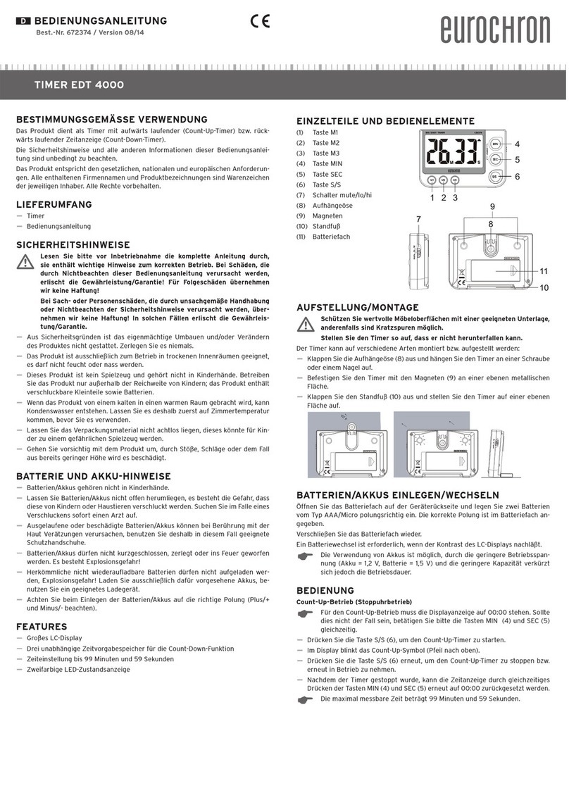
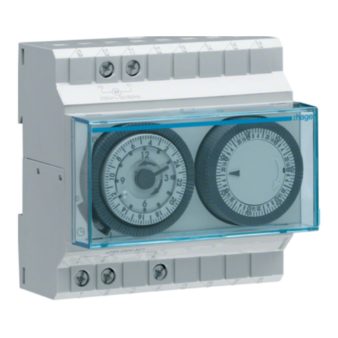
Wieland flare TIME FM6-2 230 V User manual

Bedienungsanleitung (Original)
flare TIME FM6-2 230 V 81.020.0025.0
Multifunktions-Zeitrelais
Wieland Electric GmbH
Brennerstraße 10-14
96052 Bamberg
Tel.: +49 (951) 9324-0
Fax: +49 (951) 9324-198
Internet: www.wieland-electric.com
Doc. # BA001111 - 01/2017 (Rev. A) flare TIME FM6-2 230 V DE
HINW E IS
Personal, welches dieses Gerät installiert, programmiert, in Betrieb nimmt oder wartet, muss
diese Anleitung gelesen und verstanden haben.
WARNUNG
•
Das Personal muss gründlich mit allen Warnungen, Hinweisen und Maßnahmen gemäß
dieser Betriebsanleitung vertraut sein.
•Ggf. erforderliche Schutzmaßnahmen und Schutzeinrichtungen müssen den gültigen
Vorschriften entsprechen.
•Beschädigte Produkte dürfen weder installiert noch in Betrieb genommen werden. Im Falle
eines Defekts senden Sie das Gerät zurück an Wieland Electric.
•Nur in spannungsfreiem Zustand anschließen oder trennen!
•Das Gerät darf nicht geöffnet werden.
•Führen Sie keine Fremdobjekte in das Gerät ein!
•Halten Sie das Gerät von Wasser und Feuer fern!
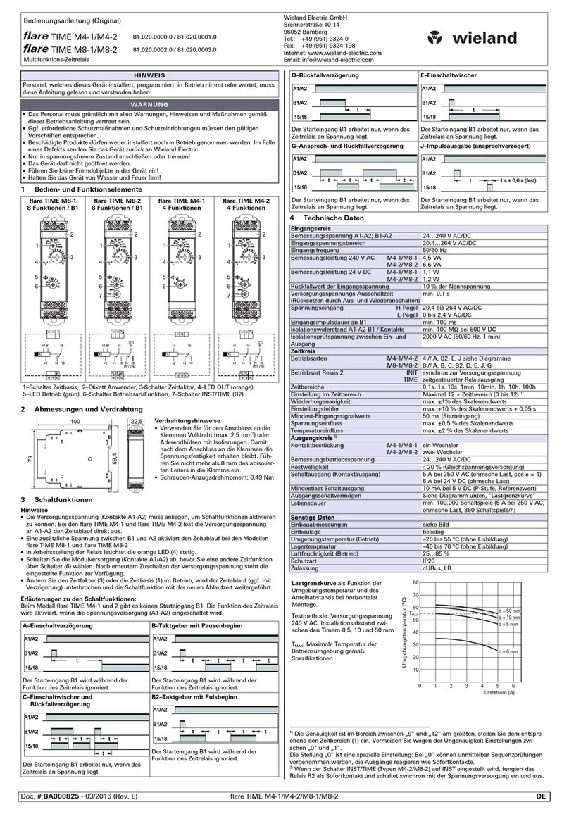
1Bedien- und Funktionselemente, LEDs
f
lare TIME FM6
-
2
Front
Rückseite
Front
1.: LED-Anzeige 1, Ist-Zeit
2.: LED-Anzeige 2, Soll-Zeit
3.: LED hh:mm
(grün, Modus aktiv)
4.: LED mm:ss
(grün, Modus aktiv)
5.: LED Status Zeitkontakt
(rot, aktiv)
6.: Drehknopf Zeit und
Zeitbereich mit Bestätigung
durch Drücken
Rückseite
1.: K1 Zeitkontakt
2.: K2 Zeit-
/Sofortkontakt
3.: X1 Versorgungs-
spannung
4.: Settings: Konfigu-
ration über DIP-
Schalter
5.: X2 Externe
Steuer-eingänge
2Abmessungen und Blechausschnitt
3Anschlussbelegung und DIP-Konfiguration
K1: Relaisausgang mit Wechslerkontakt
K2: Relaisausgang mit Wechslerkontakt
X1: Versorgungsspannung
X2: Externe Steuereingänge
Settings: DIP-Schalter-Konfiguration
DIP
-
Konfiguration
DIP
ON
OFF
Konfiguration Sofortkontakt
1
K2 = Sofortkontakt
K2 = Zeitkontakt
DIP 2-4
Bit1
Bit2
Bit3
Konfiguration Zeitfunktion
Ansprechverzögerung
Rückfallverzögerung
Einschaltwischer
Ausschaltwischer
Taktgeber Pause beginnend
Taktgeber Impuls begin
nend
DIP
ON
OFF
Konfiguration Remanenz
5
Speicherung der Zeiteinstellung
Keine Speicherung der Zeitei
n-
stellung
DIP
ON
OFF
Konfiguration der Zeitbasis
6
Zeitbasis
-
Umstellung mittels
Drehknopfprogrammierung
Zeitbasis
-
Umstellung mittels
Steuereingang (X2)
Grundeinstellung: mm:ss
HINW E IS
•
Schalten Sie die Spannungsversorgung (Kontakte A1/A2) ab, bevor Sie eine andere Konfi-
guration über die DIP-Schalter 1 - 6 wählen.
•Ist eine ungültige DIP-Konfiguration gewählt, blinken die LED-Ziffern im Frontdisplay rot.
Alle Stellen zeigen die Ziffer '8' an.
4Einstellung der Parameter über den Drehknopf
Einstellung der Sollzeit - Modus "Zeiteinstellung"
Die Einstellung der Sollzeit erfolgt für alle Zeitfunktionen einheitlich über den Drehknopf an
der Frontseite.
Um in den Modus "Zeiteinstellung" umzuschalten:
1. Drehknopf länger als 3 Sekunden (aber kürzer als 5 Sekunden) drücken.
LED-Anzeige 2 zeigt dann die aktuell gültige Zeit an (statisch), LED-Anzeige 1 zeigt die
neue, ggf. veränderte Zeit in einem Blinkrhythmus von 2 Hz an.
2. Zeit durch Drehen des Drehknopfes ändern
Im Uhrzeigersinn = Erhöhung Zeitwert, gegen den Uhrzeigersinn = Verminderung
Zeitwert.
Die Erhöhung bzw. Erniedrigung ist jeweils abhängig vom eingestellten Zeitbereich:
Zeitbereich 'hh:mm' Erhöhung bzw. Erniedrigung um 1 Minute
Zeitbereich 'mm:ss' Erhöhung bzw. Erniedrigung um 1 Sekunde
3. Durch drücken des Drehknopfs innerhalb von 10 Sekunden nach der letzten
Veränderung wird die Zeit übernommen.
Die Änderung wird übernommen und das Gerät schaltet in den Normalmodus zurück.
LED-Anzeige 1 hört auf zu blinken, beide Zeitanzeigen zeigen den gleichen Wert an.
Erfolgt innerhalb von zehn Sekunden keine weitere Betätigung am Drehknopf (Timeout),
werden die erfolgten Zeitänderungen verworfen und die zuletzt gültige Zeit wird
beibehalten. Die obere Anzeige hört auf zu blinken und das Gerät schaltet in den
Normalmodus zurück.
Einstellung der Zeitbasis - Modus 'Zeitbereichseinstellung' (nur bei DIP6 ='on')
Im Modus "Zeitbereichseinstellung" kann der Zeitbereich von "hh:mm" auf "mm:ss" und
umgekehrt umgestellt werden.
1. Drehknopf für mind. 5 Sekunden drücken, um in den Modus "Zeitbereichseinstellung"
umzuschalten.
Die beiden grünen LED's der Zeitbereiche 'hh:mm' und 'mm:ss' blinken abwechselnd mit
2 Hz.
2. Drehen am Drehknopf wählt den gewünschten Zeitbereich aus. Die LED des
ausgewählten Zeitbereichs leuchtet dabei konstant auf.
3. Drehknopf innerhalb von zehn Sekunden nach der letzten Veränderung drücken um
den Zeitbereich zu übernehmen. Das Gerät schaltet danach in den Normalmodus zurück.
Beachten Sie, dass bei Übernahme des geänderten Zeitbereichs die Sollzeit auf 00:00
gesetzt wird und dass Sie anschließend die Sollzeit neu einstellen müssen. Erfolgt
innerhalb von zehn Sekunden keine Betätigung am Drehknopf (Timeout), wird eine ggf.
erfolgte Änderung verworfen und das Gerät schaltet in den Normalmodus zurück. In
diesem Fall bleiben die vor dem Aktivieren des Modus "Zeitbereichseinstellung" gültigen
Einstellungen für den Zeitbereich und auch für die Sollzeit erhalten.
5START-STOPP-Funktionen
•Die Versorgungsspannung (Kontakte A1-A2) muss anliegen, um Schaltfunktionen aktivieren
zu können.
•Eine zusätzliche Spannung an X2, steuert die Start-(Pin1/2) und Stop-(Pin3/4) Funktion.
•Ist der Zeitkontakt K1 in Arbeitsstellung, leuchtet die rote LED Status (5).
•Nach Ablauf der eingestellten Zeit blinkt die Anzeige im Rhythmus von 2 Hz.
HINW E IS
Damit die geänderte Zeit nach einem Spannungsausfall erhalten bleibt, muss sich DIP-
Schalter DIP5 in Stellung 'on' (Remanenz, Speicherung der Zeit) befinden.
Steht DIP5 in Stellung 'off' (keine Speicherung der Zeit), ist die Sollzeit nach jeder
Wiederkehr der Versorgungsspannung mit '00:00' vorbelegt und muss dann neu eingestellt
werden.
HINW E IS
Für beide Modi 'Zeiteinstellung' und 'Zeitbereichseinstellung' gilt:
Die Einstellung der Zeit und auch der Zeitbasis ist ausschließlich bei inaktivem Zeitlauf
möglich. Bei aktivem Zeitlauf ist die Betätigung des Drehknopfes wirkungslos.
Ist eine Veränderung der Zeit und/oder des Zeitbereichs erforderlich, muss der Zeitlauf z.B.
durch Aktivieren des Stop-/Reset-Eingangs angehalten werden.
1
2
3
4
5
6
1
2
3
4
5
Normal-
modus
Modus
"Zeiteinstellung"
Knopf 3 s
drücken
Modus
"Zeitbereichs-
einstellung"
Knopf 5 s
drücken
Timeout 10 s:
=> ohne Spe
i
chern
Knopf drücken
=> neuen Wert
Speichern
Knopf drücken
=> neuen Wert
Speichern
Timeout 10 s:
=> ohne Spe
i
chern

Doc. # BA001111 - 01/2017 (Rev. A) flare TIME FM6-2 230 V DE
Erläuterungen zu den Schaltfunktionen:
Zeitfunktion AV (Bit1
-
3: off
-
off
-
on): Ansprechverzögerung
Der Zeitablauf startet, wenn der Start-Eingang auf EIN schaltet, und wird zurückgesetzt,
wenn der Start-Eingang auf AUS schaltet. Nach dem Ausschalten der Versorgung muss zum
Neustart des Zeitlaufs der Start-Eingang auf EIN wechseln. Wechselt der Stop-/Reset-
Eingang auf EIN, schalten der Zeitkontakt und der Sofortkontakt AUS.
Hinweis: Der Zeitausgang schaltet nicht, wenn die Zeiteinstellung 00:00 ist.
Zeitfunktion RV (Bit1
-
3: off
-
on
-
off): Rückfallverzögerung
Der Ausgang geht EIN, wenn der Start-Signal-Eingang auf EIN geht (außer wenn der Stop-/
Reset-Eingang auf EIN ist). Wenn die Zeit abgelaufen ist, schaltet der Ausgang AUS. Nach
dem Ausschalten der Versorgung muss zum Neustart des Zeitlaufs der Start-Eingang auf EIN
wechseln. Wechselt der Stop-/Reset-Eingang auf EIN, schalten der Zeitkontakt und der
Sofortkontakt AUS.
Hinweis: Der Zeitausgang schaltet nicht, wenn die Zeiteinstellung 00:00 ist.
Zeifunktion EW
(
Bit1
-
3: off
-
on
-
o
n
):
Einschaltwischer
Der Ausgang schaltet EIN und der Zeitablauf startet, wenn der Start-Eingang auf EIN geht.
Wenn die Zeit abgelaufen ist, wird der Zeitablauf zurückgesetzt und der Ausgang schaltet
AUS. Wechselt der Start-Eingang während des Zeitlaufs auf AUS, schaltet der Zeitausgang
AUS. Nach dem Ausschalten der Versorgung muss zum Neustart des Zeitablaufs der Start-
Eingang auf EIN wechseln. Wechselt der Stop-/Reset-Eingang auf EIN, schalten der Zeitkon-
takt und der Sofortkontakt AUS.
Hinweis: Der Zeitausgang schaltet nicht, wenn die Zeiteinstellung 00:00 ist.
Zeitfunktion AW (Bit1
-
3: on
-
off
-
on
): Ausschalt
-
Wischer
Der Ausgang schaltet EIN und der Zeitablauf startet, wenn der Start-Eingang auf AUS
wechselt. Wenn die Zeit abgelaufen ist, wird der Zeitablauf zurückgesetzt und der Ausgang
schaltet AUS. Wechselt der Start-Eingang während des Zeitlaufs auf EIN und wieder auf
AUS, bleibt der Zeitausgang EIN, der Zeitlauf wird nicht neu gestartet. Nach dem Ausschal-
ten der Versorgung muss zum Neustart des Zeitablaufs der Start-Eingang auf EIN und
anschließend nach AUS wechseln. Wechselt der Stop-/Reset-Eingang auf EIN, schalten der
Zeitkontakt und der Sofortkontakt AUS.
Hinweis: Der Zeitausgang schaltet nicht, wenn die Zeiteinstellung 00:00 ist.
Zeitfunktion TP (Bit1
-
3: on
-
on
-
off
):
Taktgeber mit Pause beginnend
Der Zeitablauf startet, wenn der Start-Eingang auf EIN geht. Zu Beginn ist der Zeitkontakt
AUS. Der Ausgang wird jedes Mal invertiert, wenn die Zeit abgelaufen ist. Solange der Start-
Eingang auf EIN ist, startet der Zeitablauf. Wechselt der Stop-/Reset-Eingang auf EIN,
schalten der Zeitkontakt und der Sofortkontakt AUS.
Hinweis: Der Zeitausgang schaltet nicht, wenn die Zeiteinstellung 00:00 ist.
Zeitfunktion TI (Bit1
-
3: on
-
on
-
on): Taktgeber mit Impuls beginnend
Der Zeitablauf startet, wenn der Start-Eingang auf EIN geht. Zu Beginn ist der Zeitkontakt
EIN. Der Ausgang wird jedes Mal invertiert, wenn die Zeit abgelaufen ist. Solange der Start-
Eingang auf EIN ist, startet der Zeitablauf. Wechselt der Stop-/Reset-Eingang auf EIN,
schalten der Zeitkontakt und der Sofortkontakt AUS.
Hinweis: Der Zeitausgang schaltet nicht, wenn die Zeiteinstellung 00:00 ist.
Technische Daten
Versorgung (X1:A1-A2)
Spannungsbereich 90…265 V AC/DC
Versorgungsspannung Frequenz
AC
50/60 Hz
Bemessungsleistungsaufnahme 2 W
Steuereingänge (X2)
Spannungsbereich 20,4… 256 V AC/DC
Bemessungsfrequenz AC 50/60 Hz
Bemessungsstrom <2 mA
Mindestimpulsdauer 100 ms
Mindestdauer zwischen zwei Sta-
tuswechseln des Steuereingangs
500 ms
Eingangsfunktionen Start; Stop-/Reset; Zeitbereichsumschaltung
Ausgang / Schaltkontakt
(K1, K2)
Kontakte 2 Wechsler, potenzialfrei
Kontaktverwendung (parametrierbar
über DIP-Schalter)
2 Zeitkontakte oder 1 Zeitkontakt (K1) + 1 Sofortkontakt
(K2)
Bemessungsspannung 250 V AC 24 V DC
Max. Dauerstrom (ohmsche Last) 5 A, 250 V AC / 30 V DC
AC15: 250 V / 1,5 A
DC13: 24 V / 0,5 A
Min. Schaltlast 5 V AC / DC, 100 mA ohmsch
Mechanische Lebensdauer 10 x 10
6
Schaltspiele
Elektrische Lebensdauer 100 x 10
3
Schaltspiele
Kontaktmaterial AgSnO
2
Zeitbereiche / Betriebsarten
Zeitbereich (2 Zeitbereiche) 1 s … 59 min 59 s
1 min … 99 h 59 min
Wiederholgenauigkeit
±
0,05
%
±
50
ms
Betriebsarten Zeitfunktionen
(6 Funktionen)
AV:
Einschaltverzögerung
RV: Rückfallverzögerung
EW: Einschaltwischer
AW: Ausschaltwischer
TP: Taktgeber, Pause beginnend
TI: Taktgeber, Impuls beginnend
Funktionsanzeige
A
–
LED
-
Zeitanzeige 1
B – LED-Zeitanzeige 2
C – Zeitbereichs-Anzeige (LED)
D – Status-Anzeige (LED)
Ziffernanzeige, vierstellig, abgelaufene Zeit, Farbe: rot
Ziffernanzeige, vierstellig, Sollzeit, Farbe: rot
Zeitbereich ‚hh:mm‘ bzw. ‚mm:ss‘ (LED grün)
Status Zeitausgang (LED rot)
Isolationseigenschaften
Isolation
s
spannung (Eingang
Ausgang)
2
.000
V AC (50
60
Hz, für 1 min)
Isolationswiderstand (A1, A2
Kontakte)
M
in. 100
MΩ bei 500
V
DC
Verschmutzungsgrad
Überspannungskategorie
2 III
Betrieb / Abmessungen / Anschluss
Betriebstemperaturbereich [T
U
] -25 …. +60 °C
Lagertemperaturbereich [T
UL
] -40 … +70 °C
Luftfeuchtigkeit im Betrieb 25 … x85 %
RH
Abmessungen Front (B x H) 72 x 72 cm
Montage Fronttafeleinbau (DIN IEC 61554)
Gehäusebefestigung Schraubklemmentechnik
Einbaumaß / Fronttafelöffnung (B x H)
68 x 68 mm (Tiefe 63 mm, ohne Steckverbinder)
Gewicht Ca. 210 g
Gehäusewerkstoff, Gehäusefarbe Kunststoff, schwarz (RAL9005)
Brandverhalten Gehäuse UL94 V0
Schutzart Front IP54 Rückseite IP20
Klemmenart Versorgung (X1) Schraubklemmen
Klemmenart Steuereingänge (X2),
Relaisausgänge
Federkraftklemmen
Schraubklemmen (X1):
Anschlussquerschnitt (ein-/feindrähtig)
Abisolierlänge
Empfohlenes Drehmoment
min. 0,14 mm² (AWG22), max. 2,5 mm² (AWG12)
6 mm
0,5 - 0,6 Nm
Federkraftklemmen (K1, K2, X2)
Anschlussquerschnitt (ein-/feindrähtig)
Abisolierlänge
min. 0,2 mm² (AWG22), max. 1,5 mm² (AWG16)
6 mm
Anschluss-/ Klemmenbelegung (s. Abb. Bedien- und Funktionselemente, LEDs)
X1 A1, A2 Versorgung Versorgungsspannung (U
I_N
)
X2 1, 2 START Steuereingang 'START'
X2 3, 4 STOP-/RESET Steuereingang 'STOP-/RESET'
X2 5, 6 TIMEBASE Steuereingang 'TIMEBASE'
K1 Wechslerkontakt (Schaltausgang, Relaiskontakte 15, 16, 18)
K2 Wechslerkontakt (Schaltausgang, konfigurierbar mit DIP1
als Zeitkontakt (Relaiskontakte 25, 26, 28) oder als
Sofortkontakt (Relaiskontakte 21, 22, 24)
Zulassungen und Normen
CE EN61812-1:2012
EMV 2004/108/EC;
Niederspannungsrichtlinie 2006/95/EC

Instruction manual (translation from original)
flare TIME FM6-2 230 V 81.020.0025.0
Multifunction time relais
Wieland Electric GmbH
Brennerstraße 10-14
96052 Bamberg
Tel.: +49 (951) 9324-0
Fax: +49 (951) 9324-198
Internet: www.wieland-electric.com
Doc. # BA001111 - 01/2017 (Rev. A) flare TIME FM6-2 230 V EN
NOTICE
Personnel which installs, programs, operates or maintains this device must have read and
understand these instructions.
WARNING
•
The personnel must be thoroughly familiar with all warnings, notes and procedures de-
scribed in these operating instructions.
•Where necessary, safety precautions and safety devices must comply with the applicable
regulations.
•Damaged products must neither be installed nor put into operation. In case of a defect,
please return the device to Wieland Electric.
•Connect or disconnect only when de-energized!
•The device may not be opened.
•Do not introduce any objects into the unit!
•Keep away from fire and water!
1Figure 1: Controls and functional components, LEDs
flare TIME FM6
-
2
Front
Back
Front
1.: LED Actual time display
2.: LED Target time display
3.: LED hh:mm
(green, mode active)
4.: LED mm:ss
(green, mode active)
5.: LED state time contact
(red, active)
6. Rotary knob for time and
time range, press to
confirm
Back
1. K1 time contact
2. K2 time contact /
instant contact
3. X1 Supply voltage
4. Settings: configu-
ration via DIP-
switch
5. X2 external
2Dimensions and sheet metal cut-out
3Connection assignment and DIP configuration
K1: Relay output with change-over contact
K2: Relay output with change-over contact
X1: supply voltage
X2: External control inputs
Settings: DIP-switch configuration
DIP
-
Konfiguration
DIP
ON
OFF
Configuration instant contact
1
K2 = instant contact
K
2 = time contact
Bit1
Bit2
Bit3
C
onfiguration time function
Delay
-
on energization
Release
-
delay
Single shot
Single shot falling edge
clock generator break starting
clock generator impulse
starting
DIP
ON
OFF
Configuration Remanence
5
Save time configuration
Do not save time configuration
DIP
ON
OFF
Konfigur
ation der Zeitbasis
6
Time base conversion via rotary
knob programming
Time base conversion via control
input (X2)
Default: mm:ss
NOTE
•
Switch off power supply (contacts A1/A3) before changing the configuration via DIP-
switches 1 - 6.
•If an invalid DIP-configuration is chosen, the LED-digits on the front display are flashing
red. All digits show the number '8'.
4Setting the parameters via the rotary knob
Configuring the target time – 'time configuration' mode
The target time for all time functions is universally configured using the rotary knob on the
front side.
To switch to 'time configuration' mode:
1. Press the rotary knob for longer than three seconds (but shorter than five seconds). The
LED display 2 then shows the currently valid time (static), while LED display 1 shows the
new, modified (if applicable) time in a flashing rhythm of 2 Hz.
2. Adjust time by turning the rotary knob. Turning the knob clockwise = increase the time,
turning the knob anti-clockwise = decrease the time. The amount of the increase or de-
crease depends on the configured time range:
time range 'hh:mm': raising or reducing by 1 minute
time range 'mm:ss': raising or reducing by 1 second
3. To accept the modified time, press the rotary knob within ten seconds of the last
change. The change is accepted and the device returns to normal mode. The LED dis-
play 1 stops flashing and the two time displays now show the same value.
If no action occurs on the rotary knob within ten seconds (timeout), any changes made
are discarded and the most recent valid time is retained. The upper display stops flashing
NOTE
To retain the modified time after a power failure, the DIP switch DIP5 must be set to 'on'
(remanence, save time).
•If DIP5 is in the 'off' position (do not save time), the target time is preset to '00:00' when
the power supply returns and must then be reconfigured.
Configuring the time base - 'time range configuration' mode (only when DIP6 ='on')
In 'time range configuration' mode, the time range can be switched from 'hh:mm' to
'mm:ss' and vice versa.
1. Press the rotary knob for at least five seconds to switch to “time range configuration”
mode.
The two green LEDs of the time ranges 'hh:mm' and 'mm:ss' flash alternately with 2 Hz.
2. Turning the rotary knob selects the required time range.
The LED of the selected time range will then stay lit.
3. Press the rotary knob within ten seconds of the last change to accept the selected
time range.
The device returns to normal mode. Be aware that when accepting the modified time
range the target time is set to 00:00 and must be reconfigured.
If no action occurs on the rotary knob within ten seconds (timeout), any changes made are
discarded and the device returns to normal mode. In this case, the settings for the time
range and target time that were valid before activating 'time range configuration' mode
are retained
NOTE
The following applies for both 'time configuration' and 'time range configuration' mode:
The time and time base can only be configured when a time sequence is inactive. If a time
sequence is active or paused, operating the rotary button has no effect.
If the modification of the time and/or time range is necessary, the time sequence must be
stopped, e.g. by activating the stop/reset input.
5START- / STOP-functions
•A1/A2: The supply voltage (contacts A1-A2) must be present in order to be able to activate
switching functions.
•An addition voltage to X2 controls the start (Pin1/2) and stop (Pin3/4) function.
•If time contact K1 is in the operating position, the red status LED lights up (5).
•After the chosen time has run out, the display flashes in a rythm of 2 Hz.
1
2
3
4
5
6
1
2
3
4
5
standard
mode
mode
'time configuration'
press button
3 s
mode 'time range
configuration'
press button
5 s
timeout 10 s: =>
without saving
press button =>
save new value
press button =>
save new value
timeout 10 s: =>
without saving

Doc. # BA001111 - 01/2017 (Rev. A) flare TIME FM6-2 230 V EN
Explanation of switching functions:
Time function AV (Bit1
-
3: off
-
off
-
on):
response
-
delay
The time sequence starts if START-input switches to ON, and is being reset if START-input
switches to OFF. After switching off the power supply the START-input must change to ON
to restart the time sequence. If the STOP-/RESET-input changes to ON the time contact and
the instant-contact switch to OFF.
Note: The time output doesn't switch if time is set to 00:00.
Time function
RV (Bit1
-
3: off
-
on
-
off):
release
-
delay
The output switches to ON if the start-signal-input switches to ON (except the stop-/reset-input
is ON). After the time sequence has expired the output switches to OFF. After switching off the
power supply the start-input must change to ON to restart the time sequence. If the stop-/ reset-
input changes to ON the time contact and the instant-contact switch to OFF.
Note: The time output doesn't switch if time is set to 00:00.
Time function
EW (Bit1
-
3: off
-
on
-
on):
Single shot
If start-input switches to ON, the output switches to ON and the time sequence starts. After
the time sequence has expired the time delay is reset and the output switches to OFF. If the
start-input switches to OFF while the time sequence is running, the time output switches to
OFF. After switching off the power supply the start-input must change to ON to restart the time
sequence. If the stop-/reset-input changes to ON the time contact and the instant-contact switch
to OFF.
Note: The time output doesn't switch if time is set to 00:00.
Time function
AW (Bit1
-
3: on
-
off
-
on):
Single shot falling edge
Output switches to ON and the time sequence starts, if the start-input switches to OFF. After
the time sequence has expired the time delay is reset and the output switches to OFF. If the
start-input switches to ON and to OFF again while the time sequence is running, the time
output stays ON. The time sequence is not restarted. After switching off the power supply the
start-input must first change to ON and then to OFF again to restart the time sequence. If the
stop-/reset-input changes to ON the time contact and the instant-contact switch to OFF.
Note: The time output doesn't switch if time is set to 00:00.
Time function
TP (Bit1
-
3: on
-
on
-
off):
clock generator break starting
The time sequence starts if start-input switches to ON. At the beginning the time contact is OFF.
The output is inverted every time after the time sequence has expired. As long as the start-input
is ON the time sequence starts. If the stop-/reset-input changes to ON the time contact and the
instant-contact switch to OFF.
Note: The time output doesn't switch if time is set to 00:00.
Zeitfunktion TI (Bit1
-
3
: on
-
on
-
on): Taktgeber mit Impuls beginnend
The time sequence starts if the start-input switches to ON. In the beginning the time contact
is ON. The output is inverted every time after the time sequence has expired. As long as the
start-input is ON the time sequence starts. If the stop-/reset-input changes to ON the time
contact and the instant-contact switch to OFF.
Note: The time output doesn't switch if time is set to 00:00.
Technische Daten
Power supply (X1:A1-A2)
Voltage range 90…265 V AC/DC
Su
pply voltage
f
requen
cy
AC
50/60 Hz
Rated consumption 2 W
Control inputs (X2)
Voltage range 20,4… 256 V AC/DC
Rated frequency AC 50/60 Hz
Rated current <2 mA
Min. impulse duration 100 ms
Min. duration between two status
changes of the control input
500 ms
Input functions Start; Stop-/Reset; time range change-over
Output / Switching contact(K1, K2)
Contacts 2 change-over contacts, potential-free
Contact usage (parameterized via
DIP-switch)
2 time contacts or 1 time contact (K1) + 1 instant contact
(K2)
Rated voltage 250 V AC 24 V DC
Max. thermal current (ohmic load) 5 A, 250 V AC / 30 V DC
AC15: 250 V / 1,5 A
DC13: 24 V / 0,5 A
Min. switching load 5 V AC / DC, 100 mA ohmsch
Mechanical life time 10 x 10
6
switching cycles
Electrical life time 100 x 10
3
switching cycles
Contact material AgSnO
2
Time ranges / Operating modes
Time range (2 time ranges) 1 s … 59 min 59 s
1 min … 99 h 59 min
Repeat accuracy
±
0,05
%
±
50
ms
Operation modes
time functions
(6 functions)
AV:
ON delay
RV: Release delay
EW: Single shot
AW: Single shot falling edge
TP: Clock generator break starting
TI: Clock generator impulse starting
Function display
A
–
LED
-
time display
1
B – LED-time display 2
C – Time range display (LED)
D – Status display (LED)
Four
-
figure n
umber display
,
elapsed time
,
color
: r
ed
Four-figure number display, target time, color: red
Time range ‚hh:mm‘ or ‚mm:ss‘ (LED green)
Status time output (LED red)
Isolation
properties
Isolation
voltage
(
input
output)
2.000
V AC (50
60
Hz, fo
r 1 min)
Isolation resistance
(A1, A2
contacts
)
Min. 100
MΩ bei 500
V
DC
Pollution degree
overvoltage category
2 III
Operation / dimensions / connectors
Operating temperature [T
U
] -25 …. +60 °C
Storage temperature [T
UL
] -40 … +70 °C
Operating humidity 25 … x85 %
RH
Dimensions front (B x H) 72 x 72 cm
Mounting Front panel mounting (DIN IEC 61554)
Mounting of the housing Screw terminal block
Installation size / front panel hole (B x
H)
68 x 68 mm (depth 63 mm, without plug-connector)
Weight App. 210 g
Housing material, housing color Plastic, black (RAL9005)
Fire behaviour of housing UL94 V0
Protection class Front IP54 back IP20
Terminal block power supply (X1) Screw terminal block
Terminal block control inputs (X2),
relay outputs
Spring-loaded terminal blocks
Spring clamps (X1):
Connector cross-section (ein-
/feindrähtig)
Abisolierlänge
Empfohlenes Drehmoment
min. 0,14 mm² (AWG22), max. 2,5 mm² (AWG12)
6 mm
0,5 - 0,6 Nm
Federkraftklemmen (K1, K2, X2)
Anschlussquerschnitt (solid-/fine-
stranded)
Conductor strip length
min. 0,2 mm² (AWG22), max. 1,5 mm² (AWG16)
6 mm
Connector-/ terminal assignment (s. fig. 1 Controls and functional components)
X1 A1, A2 Supply Supply voltage (U
I_N
)
X2 1, 2 START Control input 'START'
X2 3, 4 STOP-/RESET Control input 'STOP-/RESET'
X2 5, 6 TIMEBASE Control input 'TIMEBASE'
K1 Switching contact (switch output, relay contacts 15, 16, 18)
K2 Switching contact (switch output, configurable with DIP1
as a time contact (relay contacts 25, 26, 28) or as instant
contact (relay contacts 21, 22, 24)
Approvals and norms
CE EN61812-1:2012
EMV 2004/108/EC;
Low-Voltage Directive 2006/95/EC
This manual suits for next models
1
Table of contents
Languages:
Other Wieland Timer manuals
