15
OPERATION MODE
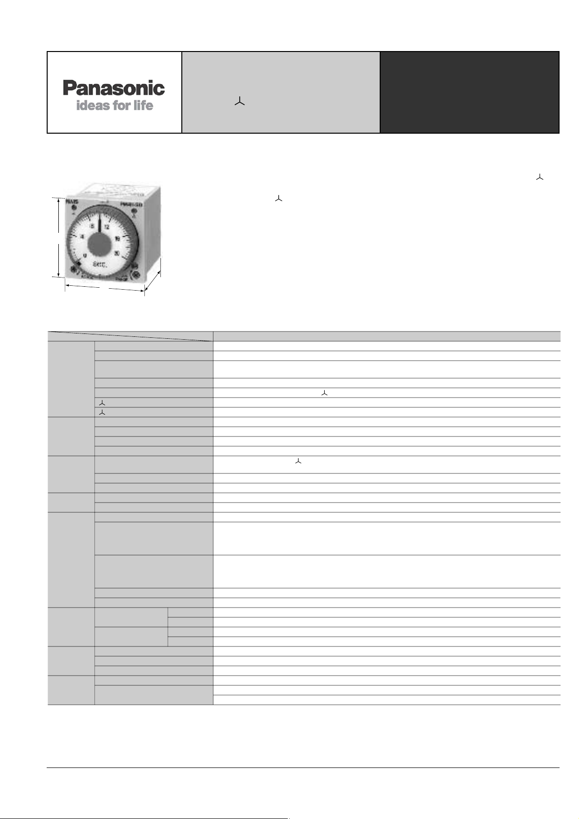
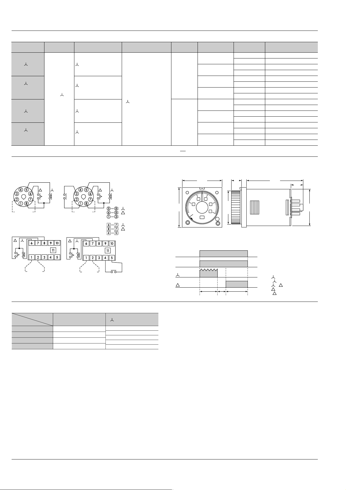
PM4H-A
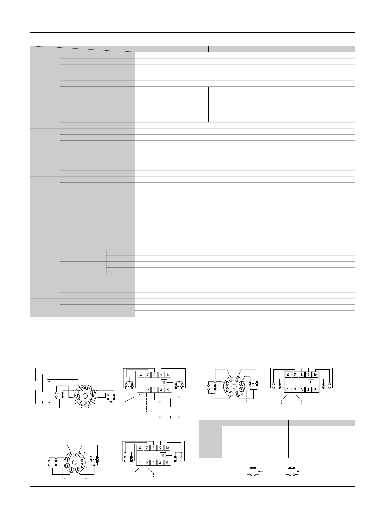
Note: Keep 0.1s or more for power off time.
Keep 0.05s or more for signal, stop, reset input time.
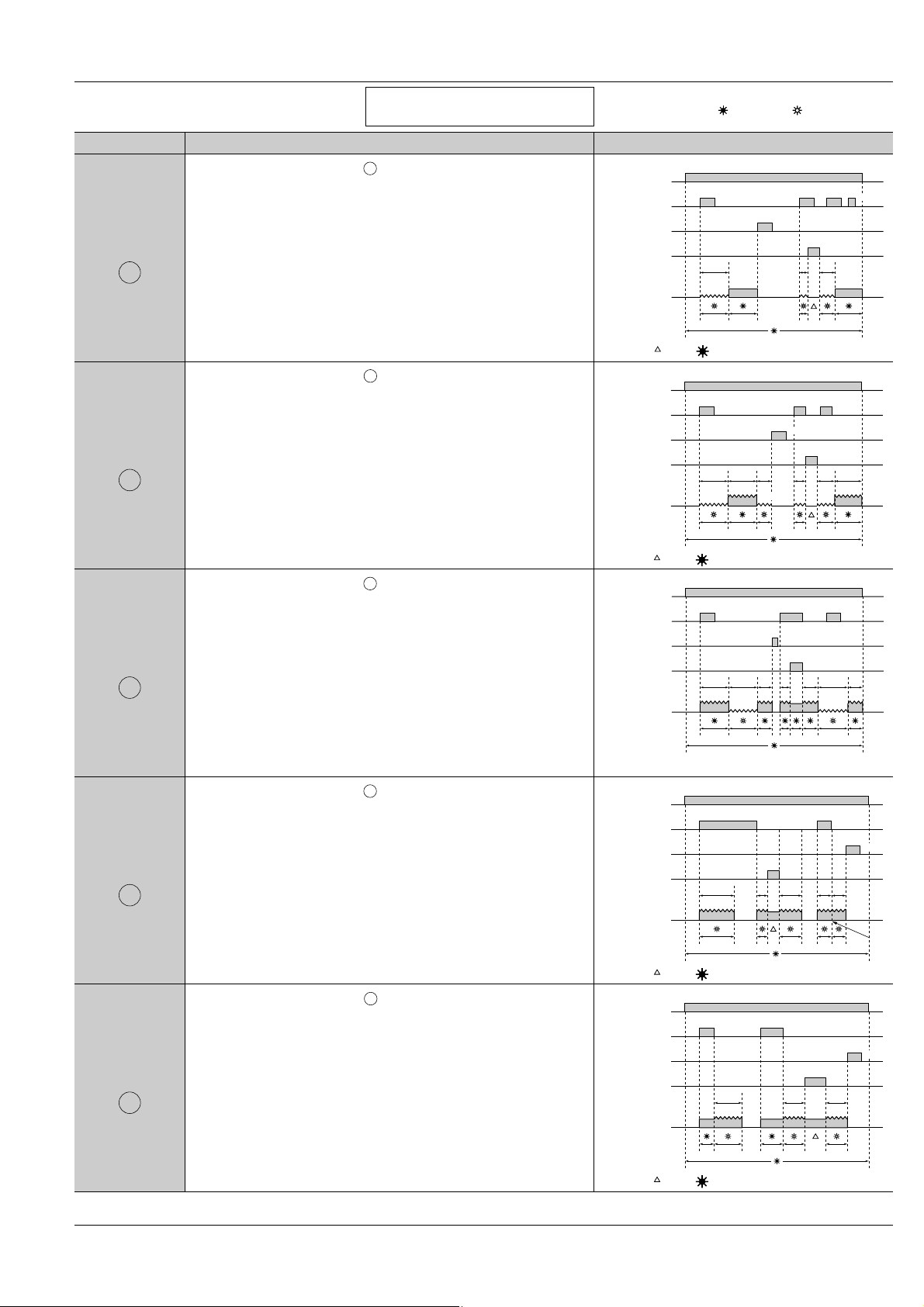
Operation mode Operation Time chart
Turn the operation selector to .
Power is applied continuously. When a start signal is applied, the
time cycle begins. The output contacts change state after the time
delay is completed. The contacts will return to their normal state
when a reset signal is applied or power is removed.
(Note: When a stop signal is applied during timing operation, the time
cycle stops. When a stop signal is removed, the time cycle begins.)
Turn the operation selector to .
Power is applied continuously. When a start signal is applied, the out-
put contacts change state immediately. When the start signal is
removed the time cycle begins. The output contacts will return to their
normal state when the time delay is completed.
Reset will occur when a reset signal is applied or power is removed.
(Note: When a stop signal is applied during timing operation, the time
cycle stops. When a stop signal is removed, the time cycle begins.)
Turn the operation selector to .
Power is applied continuously. When a start signal is applied, the out-
put contacts change state immediately and time cycle begins. The
output contacts change state after the timing cycle is completed.
When the start signal is removed, the output contacts change state
and time cycle starts again. If operation signal is turned ON or OFF
during timing operation, time cycle restart at that point.
The output contacts will return to their normal state when a reset sig-
nal is applied or power is removed.
(Note: When a stop signals is applied during timing operation, the time
cycle stops. When a stop signal is removed, the time cycle begins.)
Turn the operation selector to .
Power is applied continuously. When a start signal is applied, the out-
put contacts change state immediately and time cycle begins. When
the time delay is completed, the output contacts change state and
next time cycle begins. When the time delay is completed, the output
contacts return to the normal state.
This cycle will repeat until a reset signal is applied or power is
removed.
(Note: When a stop signal is applied during timing operation, the time
cycle stops. When a stop signal is removed, the time cycle begins.)
Turn the operation selector to .
Power is applied continuously. When a start signal is applied, the
time cycle begins but the output contacts remain in their normal state.
When the time delay is completed, the output contacts change state
and next time cycle begins. When this time delay is completed, the
output contacts return to their normal state. This cycle will repeat until
a reset signal is applied or power is removed.
(Note: When a stop signal is applied during timing operation, the time
cycle stops. When a stop signal is removed, the time cycle begins.)
Pulse
ON-delay
ON
ON
Pulse
Flicker
FL
FL
Pulse
ON-flicker
FO
FO
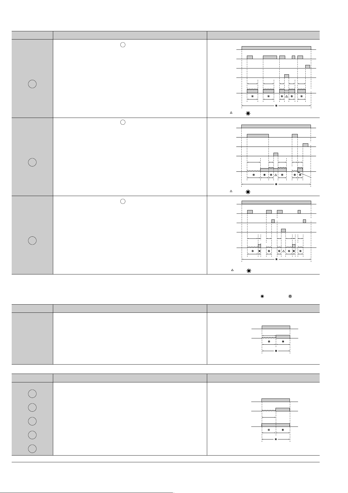
Differential
ON/OFF-delay (1)
OF1
OF1
Signal
OFF-delay
SF
SF
Power supply
ON
OFF
Operation signal
ON
OFF
ON ON
OFF
Reset
ON
OFF
Stop
ON
OFF
Time out (N.O. contact)
OP. LED
POWER LED
–
–
–
ON
Tt1t2
ON
OFFOFF
Note: LED lighting or No LED lighting
Power supply
ON
OFF
Operation signal
ON
OFF
ON
OFF
ON
OFF
OFF
Reset
ON
Stop
ON
OFF
Time out (N.O. contact)
OP. LED
POWER LED
–
–
–
ON
TT t1tat2tb
ON
OFFOFF
Note: LED lighting or No LED lighting
Power supply
ON
OFF
Operation signal
ON
OFF
ON
OFF
ON
OFF
OFF
Reset
ON
Stop
ON
OFF
Time out (N.O. contact)
OP. LED
POWER LED
–
–
–
ON
TT t2Ttatbt1
OFFOFF
Power supply
ON
OFF
Operation signal
ON
OFF
ON
OFF
ON
Reset
Stop
ON
OFF
Time out (N.O. contact)
OP. LED
POWER LED
–
–
–
ON ON
Tt1t2tatb
OFF OFF
ON
OFF
Restart
OFF
Note: LED lighting or No LED lighting
Power supply
ON
OFF
Operation signal
ON
OFF
ON
OFF
ON
OFF
ON
Reset
Stop
Time out (N.O. contact)
OP. LED
POWER LED
–
–
–
ON
Ttbta
OFF
OFF
Note: LED lighting or No LED lighting
LED lighting LED flickering
T: Setting time t1, t2, ta, tb<T t1+t2=T
PM4H-A/S/M
The new settings
are valid after power OFF ON