WIELANDER+SCHILL IM 240-i User manual
02/2022
IM 240-i
Operation Manual REV 1.0
MIG-MAG Welding Inverter

IM 240-i Operation manual
Seite 2
CONTENT
1INTRODUCTION ............................................................................................................ 4
2SETUP............................................................................................................................ 4
2.1 SETUP CONDITIONS .................................................................................................... 4
2.2 SELECTING THE ACCESSORIES .................................................................................... 4
2.4 MIG/MAG TORCH...................................................................................................... 5
2.5 TORCH WIRE LINER..................................................................................................... 6
2.6 THE FEEDING UNIT...................................................................................................... 7
2.7 WELD AREA PREPARATION .......................................................................................... 8
2.8 CONNECTING THE PRESSURE BOTTLE .......................................................................... 8
2.9 CONNECTING THE RETURN CABLE ................................................................................ 8
3SAFETY AND FIRE INSTRUCTION .............................................................................. 9
3.1 PROTECTION ............................................................................................................. 9
3.2 REMOVING THE FIRE HAZARD ...................................................................................... 9
3.3 HANDLING THE PRESSURE BOTTLES ........................................................................... 10
3.4 PROTECTION AGAINST ELECTRICAL ACCIDENTS ........................................................... 10
3.5 EXTRAORDINARY MENACE DURING WELDING ............................................................... 11
4WELDING PROCESSES ............................................................................................. 12
4.1 MIG/MAG WELDING ................................................................................................ 12
4.2 WELDING POSITIONS................................................................................................ 15
5OPERATION ................................................................................................................ 16
5.1 TURNING THE DEVICE ON ......................................................................................... 16
Operation manual IM 240-i
Seite 3
5.2 OPERATING PANEL................................................................................................... 16
5.3 SET UP,ADJUSTMENT AND DISPLAY DESCRIPTION ....................................................... 17
6CARE AND MAINTENANCE ....................................................................................... 19
6.1 DISPOSAL OFT THE MACHINE ..................................................................................... 19
7TECHNICAL DATA ...................................................................................................... 20
8AVERAGE CONSUMPTION VALUES FOR WELDING .............................................. 21
8.1 AVERAGE WELDING WIRE CONSUMPTION FOR MIG /MAG WELDING ............................. 21
8.2 AVERAGE SHIELDING GAS CONSUMPTION FOR MIG /MAG WELDING............................. 22
9TROUBLESHOOTING ................................................................................................. 23
10 DISTRIBUTORS WORLDWIDE ................................................................................... 25
11 EU- DECLARATION OF CONFORMITY ..................................................................... 26

IM 240-i Operation manual
Seite 4
1 INTRODUCTION
Dear customer!
Congratulation to purchasing of this quality inverter welding machine. Please read whole
Operation manual before you start.
1.1 Product introduction
IM 240-i welding machine is compact MIG-MAG welding inverter especially developed for
car body repair. Its excellent brazing characteristic as well as good steel welding possibilities
enables to use this device to repair all kinds of vehicles with fine quality results.
Be aware of danger resulted from welding and follow the safety and fire instructions (see the
Part 7).
It is necessary to keep the device on a dry place, to protect device against moisture. It is not
advisable to use the device on the open air during rain.
2 SETUP
2.1 Setup conditions
It´s necessary to set the device for welding in protection atmosphere on a dry place with the
sufficient area for cooling. The device is designed for use in covered area (under roof).
2.2 Selecting the accessories
Before using the machine, please make sure it was not damaged during transport!
List of accessories:
- Hose package MB15 3-meter,for steel with wire guide spiral
- DV rollers steel 0,8/0,6 mm
- Ground cable 4 m
- Operation manual

Operation manual IM 240-i
Seite 5
2.3 Connecting to the electric network
Check if the voltage stated on the device label complies with rated voltage of alternate voltage
of your electric network.
The device can be connected to electric socket equipped with protective contact installed by
authorized electrician (TN system according IEC 60364). Current circuit of socket must be
protected with 16Amp melting safety fuse or circuit breaker.
The device is delivered with plug according to CEE standard. For other connections remove
delivered plug and use certified plug according national standard..
230V Supply 110V Supply
Net Wire color Net Wire color
L Brown L1 Brown
N Blue L2 Blue
PE Yellow/Green PE Yellow/Green
2.4 MIG/MAG torch
For torch connecting is used EURO Standard torch connector. Please, tighten the connector
well to eliminate the conduction losses. A loose connection can cause damage of the machine
and torch.
Never use damaged torch!
Make sure the contact tip match the manufacturer’s recommendations for type and diameter
of used wire. Connect the welding conduction main connecting plug into the main socket on
the front side. Secure it with the lock nut.
In case Teflon liner is used is it necessary to use contact neck liner out of brass to provide
good current conduction to the fill wire.
IM 240-i Operation manual
Seite 6
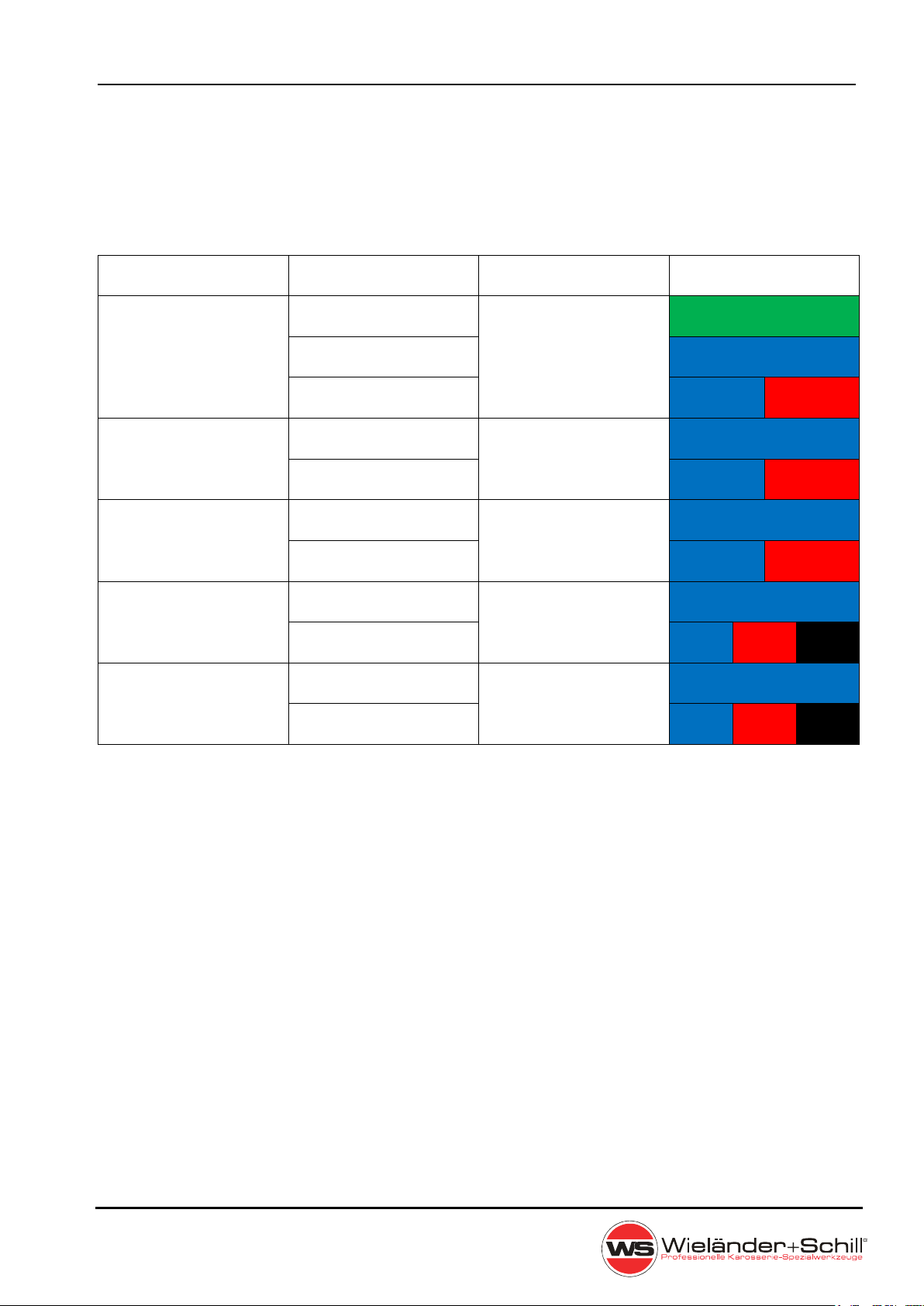
2.5 Torch wire liner
For mild steel, the wire feed tube - a liner for welding - consists of a steel spiral. When using
wire electrodes made of chromium / nickel steel and of aluminum and other metals, a tube of
wear-resistant plastic (for example Teflon) is used. Plastic guides have a lower friction
coefficient than steel.
Material Wire diameter Liner material Liner color
0,6mm Steel spiral
Fe 0,8mm or
Teflon
1,0mm
Inox 0,8mm Teflon
1,0mm
AlMg, AlSi 0,8mm Teflon
1,0mm
CuSi3 0,8mm Teflon
1,0mm
CuAl8 0,8mm Teflon
1,0mm
Liner color:
Blue: Art.N° 337139 Red: Art.N° 337142 Black: Art.N° 337147
Green: Art.N° 337107

Operation manual IM 240-i
Seite 7
2.6 The feeding unit
Please choose the feeding rolls correspond to used welding wire.
Material Shape Diameter Article-Number
Fe
Inox
CuSi
CuAl
0,6/0,8mm
0.8/1.0mm
337219
337220
AlMg
AlSi
0,8/1,0mm
xxx
When the feeding wheel is set up, you can see on the front side of the wheel the assigned
welding wire diameter (value is in mm).
Feeding
rolls
Fixing
point
Pressure
adjustment

IM 240-i Operation manual
Seite 8
2.7 Weld area preparation
A work piece must be clean in the welding area, free of paint, metallic coat, dirt, rust, fat and
moisture. The preparation of weld must be according to technical instructions for welding.
2.8 Connecting the pressure bottle
Make sure You are using right gas according welded material.
Set the pressure bottle to the stand intended for it and fasten it by belt to the holder on the
back side of the device. Open a cover and after that open the bottle valve for a short time
in order that the gas flows away from your body. Screw a reduction valve on the pressure
bottle. Connect a hose to the MIG-MAG welding device reduction valve. The recommended
gas flow is 8 – 15 liter/minute in a room without draft.
If you use an adjustable reduction valve, you can adjust a gas flow with a toggle nut with a
liter scale. The device must be turned on and gas-check function activated the welding
button must be pressed during adjustment.
It`s not allowed to repair pressure valves. It`s necessary to send the defective reduction val-
ves to service.
2.9 Connecting the return cable
It`s necessary to connect the grounding clamp in the very vicinity of welded place. The
transfer contact must be metallic clear free of dust and color.

Operation manual IM 240-i
Seite 9
3 SAFETY AND FIRE INSTRUCTION
Keep this device out from children. You have to follow the safety and fire instruction when
you work with welding device for welding in protective atmosphere. Regulations for preven-
ting of accidents during "welding, cutting and similar working activities".
3.1 Protection
A welder should wear a closed and dry working dress (non-flammable welding dress is the
best), firm insulating shoes (jackboots), cap and leather sleeve gloves.
-
Clothing made from synthetic materials and half shoes are improper.
-
Insulating gloves on both hands protect against electricity (welding circuit no load run),
harmful radiation (heat and U.V. radiation), and also against flaming metal and slag
drops. The effect of U.V. radiation on the uncovered body parts is similar as sunburn.
It`s necessary to wear an appropriate eye protection against sparks, heat, visible and invi-
sible radiation (protective shield or protective helmet equipped with protective glass from the
10-th to 15-th grade according to DIN 4647 standard, depending on used current).
-
Do not look into an electric arc with unprotected eyes (you can go blind or you can burn).
Invisible U.V. radiation causes a very painful eye conjunctiva inflammation without eyes
protection, which rises even after couple of hours.
-
Weld nearby the other persons, which are able to help you fast in a case of emergency.
-
The persons or assistants present nearby an electric arc have to be advised about hazard
and must be equipped with a necessary protective equipment.
-
A working places situated in the neighborhood have to be protected with proper shields
against radiation.
-
It`s necessary to ensure air supply and exhaustion in closed rooms and buldings. The
toxic vapors evaporate from metal coats and anticorrosive paints due to heat from the
electric arc during welding.
3.2 Removing the fire hazard
Follow this instructions before welding starts:
-
Remove inflammable materials and objects in 5 meter ring from the welding place.
-
The inflammable materials and objects which could not be removed must be protected by
covering with steel plates, wet rags etc..
-
It`s necessary to cover or tighten the holes, cracks in walls etc. due to uncontrollable
sparking.
-
Prepare the fire extinguisher, bucket of water etc.

IM 240-i Operation manual
Seite 10
-
Be conscious of possibility of hidden fire on covered objects or in another rooms due tu
heat transfer.
- After finishing of welding check up the welding place for smoking parts or small fires
in
the time interval up to 6 or 8 hours.
3.3 Handling the pressure bottles
You have to follow respective safety regulations (technical regulations for pressure gas TRG
253 and 303).
Due to high presure inside the bottles (up to 200 bar) it is necessary to secure them against
mechanical damage, overturning, downfall, heating up (max 50°C), against sunshine expo-
sure for a longer time and against strong frost.
-
When the MIG/MAG device is being equipped with pressure bottle, you have to keep on
mind that the bottle could cause overturn of device on an uneven surface. To prevent
this kind of accident you should use an appropriate pressure bottles.
-
Filling of the bottles is allowed only by specialized companies.
3.4 Protection against electrical accidents
It`s not allowed to carry the torch under armpit or to hold it in such way, that a current could
flow through human body. The device must be switched off during the longer breaks. When
the welding is finished and before moving, the device must be un-plugged from the power
supply. It is necessary to cut immediately off the power supply in a case of accident.
To prevent uncontrollable welding back current you have to connect the welding supply di-
rectly to the work piece by working clamp. The pipes, steel constructions etc... must not be
„electric conductors“ in any case, if they are not welded themselves.
Follow this instructions in any case:
The welding current must not have any conductive connection with protective or zero con-
ductor of the power supply network. Because the protective contact of power supply is con-
nected to welding device, you must not put the grounding clamp down on the welding device
body, when the device is connected to power supply network. The workpiece must be
insulated from power supply protective and zero conductor and from the grounding con-
ductor.

Operation manual IM 240-i
Seite 11
3.5 Extraordinary menace during welding
-
It`s not allowed to weld in rooms with increased “danger” of fire or explosion. The special
regulations must be followed in this areas.
-
It`s not allowed to weld in tanks for gas, fuel, oil, paint etc., even if they are empty for a
long time. The remnant of content could cause an explosion.
-
The welds exposed to an extraordinary strain must comply to strict safety regulations and
can be welded only by trained and examined welders (e.g. pressure tanks, rails, drawing
devices for cars, supporting structures).
IM 240-i Operation manual
Seite 12
4 WELDING PROCESSES
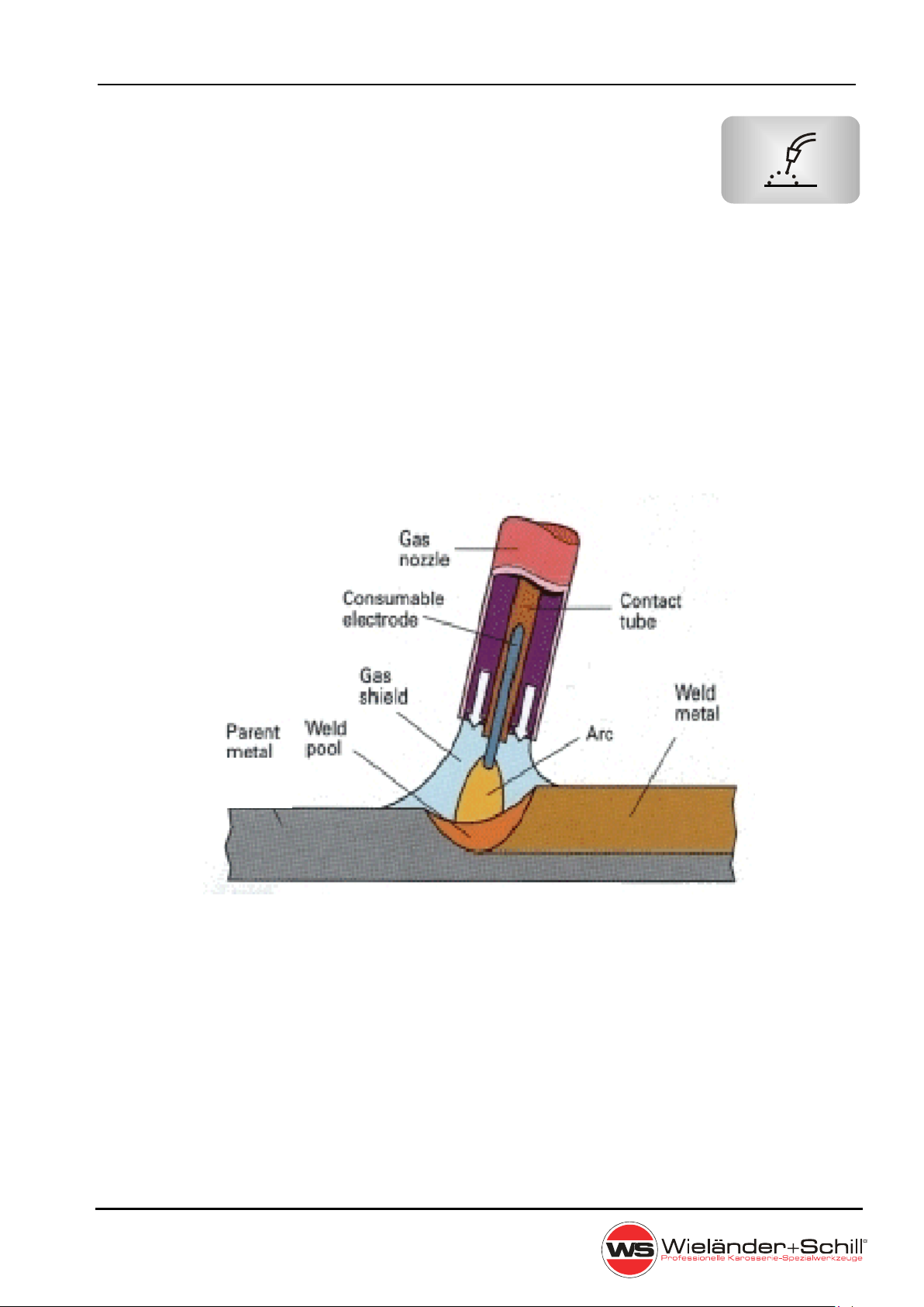
4.1 MIG/MAG Welding
Partial mechanical gas shielded arc welding (MIG), optionally as MIG (inert gas welding, EN
ISO 4063: process 131) or MAG welding (metal welding with active, ie reactive gases, EN ISO
4063: process 135), is an arc welding process in which the consumable welding wire is
continuously tracked by a variable speed motor. The usual welding wire diameters are
between 0.8 and 1.2 mm (more rarely 0.6 mm). Simultaneously with the wire feed the welding
point is supplied via a nozzle the protective or mixed gas with about 10 l / min (rule of thumb:
inert gas volume flow 10 l / min per mm welding wire diameter). This gas protects the liquid
metal under the arc from oxidation, which would weaken the weld. In metal active gas (MAG)
welding, either pure CO2 or a mixed gas of argon and small amounts of CO2 and O2 (e.g.,
"Corgon") is used. Depending on their composition, the welding process (penetration, drop
size, splash losses) can be actively influenced; Metal inert gas welding (MIG) uses argon as
a noble gas, and more rarely also the expensive noble gas helium. The MAG process is
primarily used for steels, the MIG process preferred for non-ferrous metals.
MIG/MAG welding process
For the MIG / MAG welding process, a DC current with decreasing characteristic and plus
potential at the welding wire is used.
MIG / MAG welding uses different types of arc used based on voltage and wire feed speed -
short arc, mixed arc, spray arc.
In addition to the standard arc types, there are other special shapes for special applications.

Operation manual IM 240-i
Seite 13
Arc ranges for 1.0mm Fe G3Si wire
Short Arc
The short arc occurs in the lower power range, at lower current intensities and
arc voltages.
Short arc transfer time
The arc length changes cyclically. Thus, working point shifts of welding current and welding
voltage are connected. In the phase of droplet detachment, by approaching the droplet to
the melt, the arc flash voltage decreases until the droplet passes into the molten bath. There
is a short circuit, the current increases according to the inductance of the welding circuit up
to the maximum short-circuit current. The current increase rate of the current source
determines the type of droplet separation significantly. After re-ignition of the arc, the voltage
increases suddenly. The welding current drops again and adjusts itself according to the
position of the arc operating point on the current source characteristic. The course of the
instantaneous welding current is essentially determined by the dynamic properties of the
welding current source. In modern welding power sources, these properties are generated
selectively by means of control and regulation. During the drop short, the measurable
voltage does not completely collapse, as the heated free wire length has a distinctively
dynamically changing resistance. This process is repeated between 20 to 100 times per
second.

IM 240-i Operation manual
Seite 14
Mixed Arc
Mixed arc transfer time view
Between the arc types short and spray arc is the mixed arc which is characterized by strong
spatter formation.
Spray Arc
Spray arc transfer time view
The spray arc burns continuously without a short-circuit interruption. The material transfer
from the wire electrode into the weld pool is fine-droplet. It is relatively high thermal energy
introduced into the weld metal, which is why heat affected zone and thus the workpiece
distortion are greater than the short arc. This type of arc is used to weld thicker sheets.
Operation manual IM 240-i
Seite 15
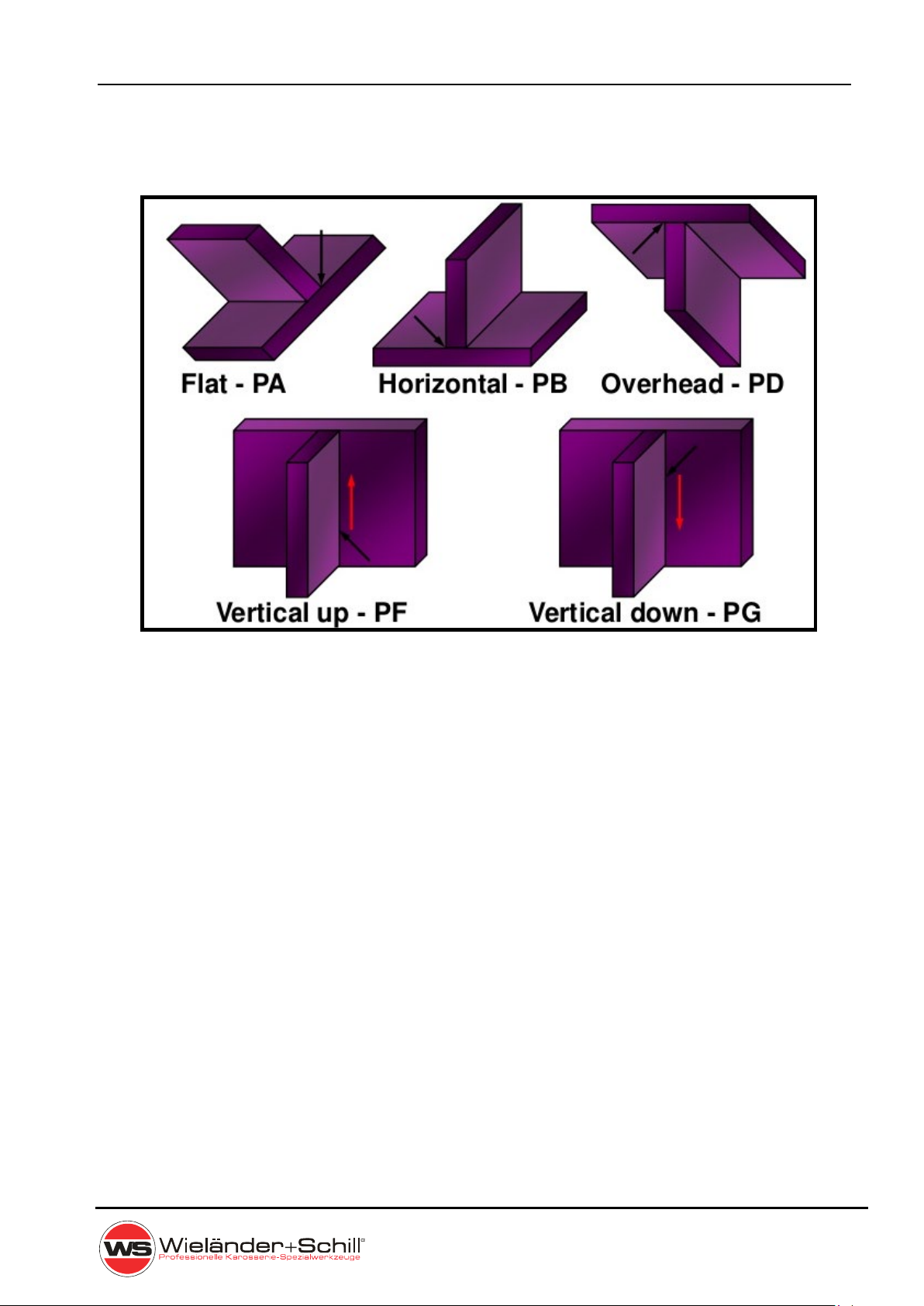
4.2 Welding Positions

IM 240-i Operation manual
Seite 16
5 Operation
5.1 Turning the device ON
Always use the main switch to turn On and Off the device, never use the power plug for this
purpose!
Power-on sequence
After powered special power on sequence is started on the operating panel, to give the user
information about the firmware.
a) Firmware type (in voltage window)
Fm – Front panel IM
b) Amperage rating (in Ampere window)
200 – 200Amp
c) Firmware revision (in Ampere window)
„r1.1“ = major . minor revision numbers.
5.2 Operating Panel
Filler wire material selection
FeSg2 (MIX) - Standard, not alloyed steel,
shielding gas: 82%Ar + 18%CO2
FeSg2 (CO2) - Standard, not alloyed steel,
shielding gas: 100% CO2
AlMg - Aluminium + Magnesium
shielding gas: 100%Ar
AlSi5 - Aluminium + 5% Silicium,
shielding gas: 100%Ar
AlSi12 - Aluminium + 12% Silicium,
shielding gas: 100%Ar
CuSi3 - Kupfer + 3% Silizium
shielding gas: 100%Ar
Manual - Manual setup of wire speed and welding voltage
Operation manual IM 240-i
Seite 17
Filler wire diameter selection
0,6mm
0,8mm
1,0mm
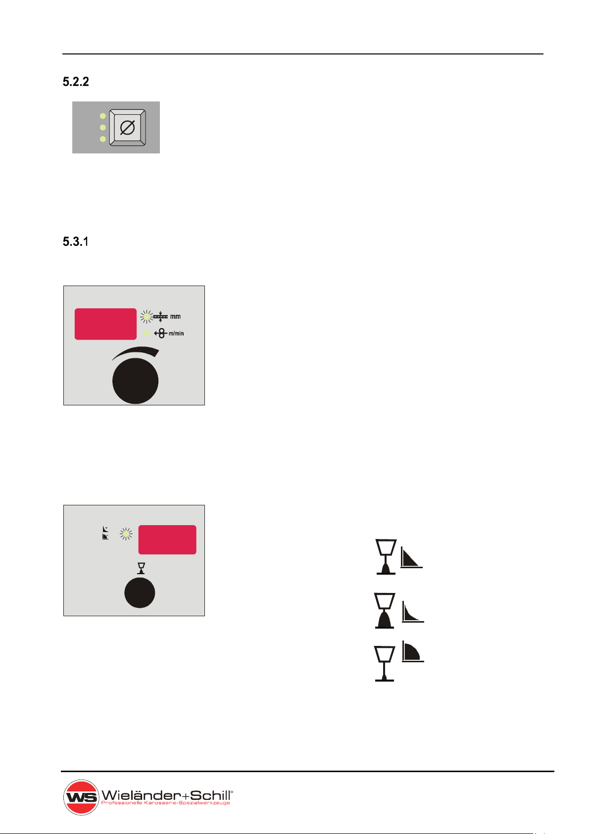
5.3 Set up, adjustment and display description
Synergic mode
5.3.1.1 Welding power set up
IM 240-i machines can be controlled with full synergic
feature. The welding power is to adjust just with one main
rotary encoder. By setup of material thickness (in
millimeters) are automatically set all welding parameters .
5.3.1.2 Arc length correction
There is possible to adjust length of the welding arc. By
turning the encoder in any direction is display switching
from Voltage mode to Arc length correction mode (% LED
Active).
Arc length = 0 –
Arc length = +30 –
Arc length = –30 –
0.8mm
0. mm6
10. mm
AMP
%
VOLT

IM 240-i Operation manual
Seite 18
Manual mode
5.3.2.1 Wire speed setup
Set up wire feed speed in m/min by turning the encoder.
5.3.2.2 Welding voltage setup
Set up the welding voltage in Volts by turning the encoder.
5.3.2.3 Arc length correction
There is possible to adjust length of the welding arc. By
turning the encoder in any direction is display switching
from Voltage mode to Arc length correction mode (% LED
Active).
Arc length = 0 –
Arc length = +30 –
Arc length = –30 –
AMP
%
VOLT
%
VOLT

Operation manual IM 240-i
Seite 19
6 CARE AND MAINTENANCE
Pull out the power cable from the socket before every maintenance and troubleshooting.
The device is almost maintenance free.
It is necessary to check feeding wheel, pressure roller and inflow nozzle regularly, if there is
not some dirt. If it is, you have to clean it out.
Please, change the contact tip on the torch regulary.
The complete set of pressure hoses should be cleaned up from time to time, because of
embedded dust and parts.
The contact nozzle of the torch is wearing up subsequently. When the hole in the nozzle is
too large, it is necessary to change the nozzle. The metal drops are embedding in the inner
walls of the torch cover. Take them out if necessary. The separator is helpful and it is also
a prevention against the firm caking of the drops.
You have to change the damaged cables at once.
6.1 Disposal oft the machine
Do not dispose of electrical equipment together with the normal waste!
In observance of European Directive 2002/96/EC on Waste Electrical
and Electronic Equipment and its implementation in accordance with
national law, electrical equipment that has reached end of its life must
be collected separately and returned to an environmentally compatible
recycling facility.

IM 240-i Operation manual
Seite 20
7 TECHNICAL DATA
IM 240-i:
Mains connection 1~ 230V +10/-15%
2~200V +15/-5%
Mains cable 3x2.5qmm
Fusing 16Amp delayed
Load capacity 20% @200Amp/24V
60% @140Amp/21V
100% @ 120Amp/20V
Peak input current I1p 230V 32Amp @200Amp/24V
200V 37Amp @200Amp/24V
Effective maximum input current I1eff 230V 15Amp @200Amp/24V/20%
200V 16Amp @200Amp/24V/20%
No load output voltage Uo 40.2V
Efficiency 85%
Idle power consumption in MIG mode 25W
Power factor 0.75
Current adjustment range 20 – 200Amp
Voltage adjustment range 10 – 35V / 0.1V step
Wire speed range 1.5 – 15 m/min
Wire feed roll diameter 37mm
Wire spool diameter 300mm max / 17kg max
Thermal class H(180°C)
Temperature range -10 ….+40°C - operating temp.
-40 ….+80°C - storage temp.
Dimensions LxWxH 900x500x840mm
Weight 40kg
Degree of protection IP23
EMC Class A
The product meet requirements for CE and S marking.
Other manuals for IM 240-i
1
Table of contents
Other WIELANDER+SCHILL Welding System manuals


Popular Welding System manuals by other brands


Harbor Freight Tools
Harbor Freight Tools Vulcan Migmax 215 Owner's manual & safety instructions

Top Gun
Top Gun MIG-MAG 250I-SWF Operation manual

Blaupunkt
Blaupunkt WM2000 manual

Murex
Murex Transmatic 4C Instruction manual and spare parts list

ARC
ARC 160 operating manual

Kemppi
Kemppi A7 Cooler operating manual