WIELANDER+SCHILL InvertaPuls IP4-3 User manual

InvertaPuls IP4-3
02/2021
MIG-MAG Welding Inverter
Operation Manual REV 2.1

InvertaPuls IP4-3 Operation Manual
Page 2
CONTENT
1INTRODUCTION ............................................................................................................ 4
1.1 PRODUCT INTRODUCTION ........................................................................................... 4
2SETUP............................................................................................................................ 4
2.1 SETUP CONDITIONS .................................................................................................... 4
2.2 SELECTING THE ACCESSORIES .................................................................................... 4
2.3 CONNECTING TO THE ELECTRIC NETWORK .................................................................... 5
2.4 CONNECTING THE MIG/MAG TORCH ........................................................................... 5
2.5 TORCH WIRE LINER..................................................................................................... 6
2.6 THE FEEDING UNIT ...................................................................................................... 7
2.7 CONNECTING THE PRESSURE BOTTLE .......................................................................... 7
2.8 CONNECTING THE GROUND CABLE ............................................................................... 8
2.9 MMA –TIG WELDING CONNECTION ............................................................................ 8
3SAFETY AND FIREINSTRUCTION ............................................................................... 9
WELDING IN THE ENVIRONMENT WITH HIGHER ELECTRICAL DANGER......................................... 10
4OPERATION ................................................................................................................ 11
4.1 SWITCHING ON THE MACHINE ................................................................................... 11
4.1.1 Power-on sequence........................................................................................ 11
4.2 OPERATING PANEL................................................................................................... 11
4.2.1 Welding mode selection ................................................................................. 12
4.2.2 Welding process selection.............................................................................. 14
4.2.3 Selection of the additional material................................................................. 15
4.2.4 Selection of the additional material diameter.................................................. 16
4.2.5 MENU............................................................................................................. 16
4.2.5.1 Global menu parameters ............................................................................. 17
4.3 SET UP,ADJUSTMENT AND DISPLAY DESCRIPTION........................................................ 18
4.3.1 Welding power set up ..................................................................................... 18
4.3.2 Arc length correction synergic mode .............................................................. 18
4.4 JOB MODE.............................................................................................................. 19
4.4.1 Editing / saving the JOB ................................................................................. 19

Operation Manual InvertaPuls IP4-3
Page 3
4.5 SELECTING THE ACTIVE FEEDER ................................................................................ 19
4.6 PARAMETERS SETUP FOR DIFFERENT FEED UNITS ....................................................... 19
4.7 ARC CONTROL........................................................................................................ 20
4.8 FACTORY SETUP ...................................................................................................... 20
5MAINTENANCE ........................................................................................................... 21
5.1 DISPOSAL OF THE MACHINE....................................................................................... 21
6TECHNICAL DATA ...................................................................................................... 22
7AVERAGE CONSUMPTION VALUES FOR WELDING .............................................. 24
7.1 AVERAGE WELDING WIRE CONSUMPTION FOR MIG /MAG WELDING ............................. 24
7.1.1 Steel welding wire .......................................................................................... 24
7.1.2 CrNi welding wire............................................................................................ 25
7.1.3 Aluminium welding wire .................................................................................. 25
7.1.4 CuSi welding wire ........................................................................................... 25
7.2 AVERAGE SHIELDING GAS CONSUMPTION FOR MIG /MAG WELDING............................. 26
7.2.1 MIG / MAG steel welding................................................................................ 26
7.2.2 MIG / MAG aluminium welding ....................................................................... 26
7.3 AVERAGE SHIELDING GAS CONSUMPTION FOR WIG WELDING ....................................... 26
8TROUBLESHOOTING ................................................................................................. 26
9DISTRIBUTORS WORLDWIDE ................................................................................... 29
10 EU-DECLARATION OF CONFORMITY ...................................................................... 30
InvertaPuls IP4-3 Operation Manual
Page 4
1 INTRODUCTION
1.1 Product Introduction
InvertaPuls IP4-3 welding machine is compact pulse MIG-MAG welding inverter especially
developed for car body repair. The unique benefit is triple wire feed unit which together with
its excellent welding properties for thin sheet metal as well as aluminum and CuSi makes it
possible to use this device to repair all kinds of vehicles with fine quality results.
Be aware of danger resulted from welding and follow the safety and fire instructions.
It`s necessary to keep the device on a dry place, to protect device against moisture. It`s not
advisable to use the device on the open air during rain.
2 SETUP
2.1 Setup conditions
It´s necessary to set the device for welding in protection atmosphere on a dry place with the
sufficient area for cooling. The device is designed for use in covered area (under roof).
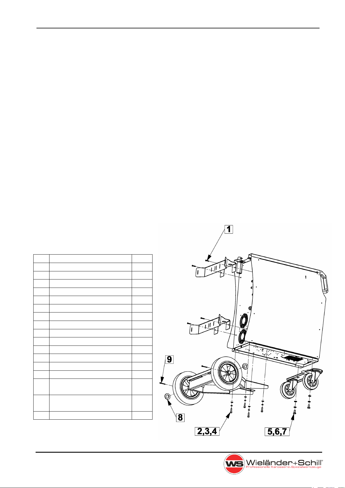
2.2 Selecting the accessories
Please check the machine for possible
transport damages before use!
1.
screw M5x16
4St
2.
screw M8x16
4 St
3.
spring washer M8
4 St
4.
U-disc M8
4 St
5.
screw M10x40
2 St
6.
spring washer M10
2 St
7.
U-disc M10
2 St
8.
U-disc M24
2 St
9.
split pin 3.5x40
2 St
10.
2x20l place for gasbottle
1 St
11.
front wheel set
1 St
12.
rear wheels
2 St
13.
rear axle
1 St
14.
gas connecting hose
3 St
15.
belt for gas bottle
4 St
16.
MIG torch,
Steel Version
1 St
17.
MIG torch,
CuSi/Alu Version
1 St
18.
ground cable
1 St

Operation Manual InvertaPuls IP4-3
Page 5
2.3 Connecting to the electric network
Check if the voltage stated on the device label complies with rated
voltage of alternate voltage of your electric network.
The device can be connected to electric socket equipped with protective contact installed
by authorized electrician. The electrical circuit of the socket must be protected by a fuse or
a circuit breaker.
Refer to the Technical Data on pages 22-23 for the required amperage.
The device is delivered without plug. For connections can be used only plugs and sockets
according to CEE standard.
2.4 Connecting the MIG/MAG torch
- For torch connecting is used EURO Standard torch
connector.
- Please, tighten the connector well to avoid the contact
resistance.
- Never use damaged torch.
Connect the welding conduction main connecting plug into the main socket on the front
side. Secure it with the lock nut.
Work piece
clamp
Torch A
Torch B
Torch B
state LED
Torch A
State LED
Torch C
Torch C
state LED

InvertaPuls IP4-3 Operation Manual
Page 6
2.5 Torch wire liner
For mild steel, the wire feed tube consists of a steel spiral. When using wire electrodes
made of chromium-nickel-steel and of aluminum and other metals, a tube of wear-resistant
plastic (for example Teflon) is used. Plastic guides have a lower friction coefficient than
steel.
Make sure the contact tip match the manufacturer’s recommendations for type and diameter
of used wire.
In case Teflon liner is used is it necessary to use contact neck liner out of brass to provide
good current conduction to the fill wire.
Material Wire diameter Liner material Liner color
Fe 0,8mm steel spiral
or
Teflon
1,0mm
1,2mm
Inox 0,8mm Teflon
1,0mm
1,2mm
AlMg, AlSi 1,0mm Teflon
1,2mm
CuSi3 0,8mm Teflon
1,0mm
1,2mm
CuAl8
0,8mm Teflon
1,0mm
Liner color:
Blue: Art.N° 337139 Red: Art.N° 337142 Black: Art.N° 337147

Operation Manual InvertaPuls IP4-3
Page 7
2.6 The feeding unit
Please choose the feeding rolls correspond to used welding wire.
Material
Shape
Diameter
Article-Number
Fe
Inox
CuSi
CuAl
0,6/0,8mm
0.8/1.0mm
1,0/1,2mm
337219
337220
xxx
AlMg
AlSi
0,8/1,0mm
1.0/1.2mm
xxx
337221
When the feeding wheel is set up, you can see on the front side of the wheel the assigned
welding wire diameter (value is in mm).
2.7 Connecting the pressure bottle
While adjusting the gas flow rate, the unit must be switched on and the burner switch must
be pressed to open the solenoid valve. To avoid unnecessary wire consumption, open the
leaf spring of the wire feeder.
Determination of the gas flow rate:
Steel - 10x wire Ø
Aluminium - 12x wire Ø
Example: Wire Ø 0,8mm x 10 = 8Liter/minute
Pressure
adjustment
Feeding
rolls
Fixing
point

InvertaPuls IP4-3 Operation Manual
Page 8
2.8 Connecting the ground cable
It`s necessary to connect the grounding clamp in the very vicinity of welded place. The
transfer contact must be metallic clear free of dust and color.
2.9 MMA – TIG welding connection
TIG Connection MMA Connection
Work
piece
TIG Torch
Stick Holder

Operation Manual InvertaPuls IP4-3
Page 9
3 SAFETY AND FIREINSTRUCTION
Keep this device away from children. You must follow the safety and fire instructions when
you work with the welding device and for welding in a protective atmosphere. Follow all
regulations for the prevention of accidents during "welding, cutting and similar working
activities".
WARNING FIRE HAZARD!
Be sure the area is safe before doing any welding.
Remove all flammable material within 10m of the welding area.
Quench hot metal or allow it to cool before handling or before letting
it touch combustible materials.
Never weld containers with potentially flammable materials inside –
they must be emptied and properly cleaned first.
Ventilate potentially flammable atmospheres before welding
WARNING EXPLOSION RISK!
It’s possible that harmless substances in closed containers may
generate excessive pressure when heated.
Move containers with flammable or explosive liquids away from the
working area!
Never heat explosive liquids, dusts or gases by welding!
CAUTION TOXIC FUMES!
Smoke and gases can lead to breathing difficulties and poisoning
Use local exhaust ventilation to remove fumes from the air.
Remove all coatings and solvents from the metal before welding.
Wear suitable breathing apparatus if appropriate!
Never weld containers with potentially toxic materials inside. Empty
and properly clean the container first.
CAUTION Noise exposure!
Prolonged exposure to noise from welding, cutting or similar work
can damage hearing.
Use approved ear protection.
Warn others nearby about the noise hazard.
WARNING ARC RAYS CAN BURN EYES AND SKIN!
The welding arc produces intense visible and invisible rays that can
burn eyes and skin.
Wear eye protection (welding helmet) with appropriate lens shading
to protect your eyes from the arc’s ultraviolet and infrared rays.
Wear protective clothing to protect against burns caused by
ultraviolet light, sparks and hot metal.
Flame-retardant clothing to cover all exposed areas.
Use protective screens or barriers to protect others from flash and
glare.
InvertaPuls IP4-3 Operation Manual
Page 10
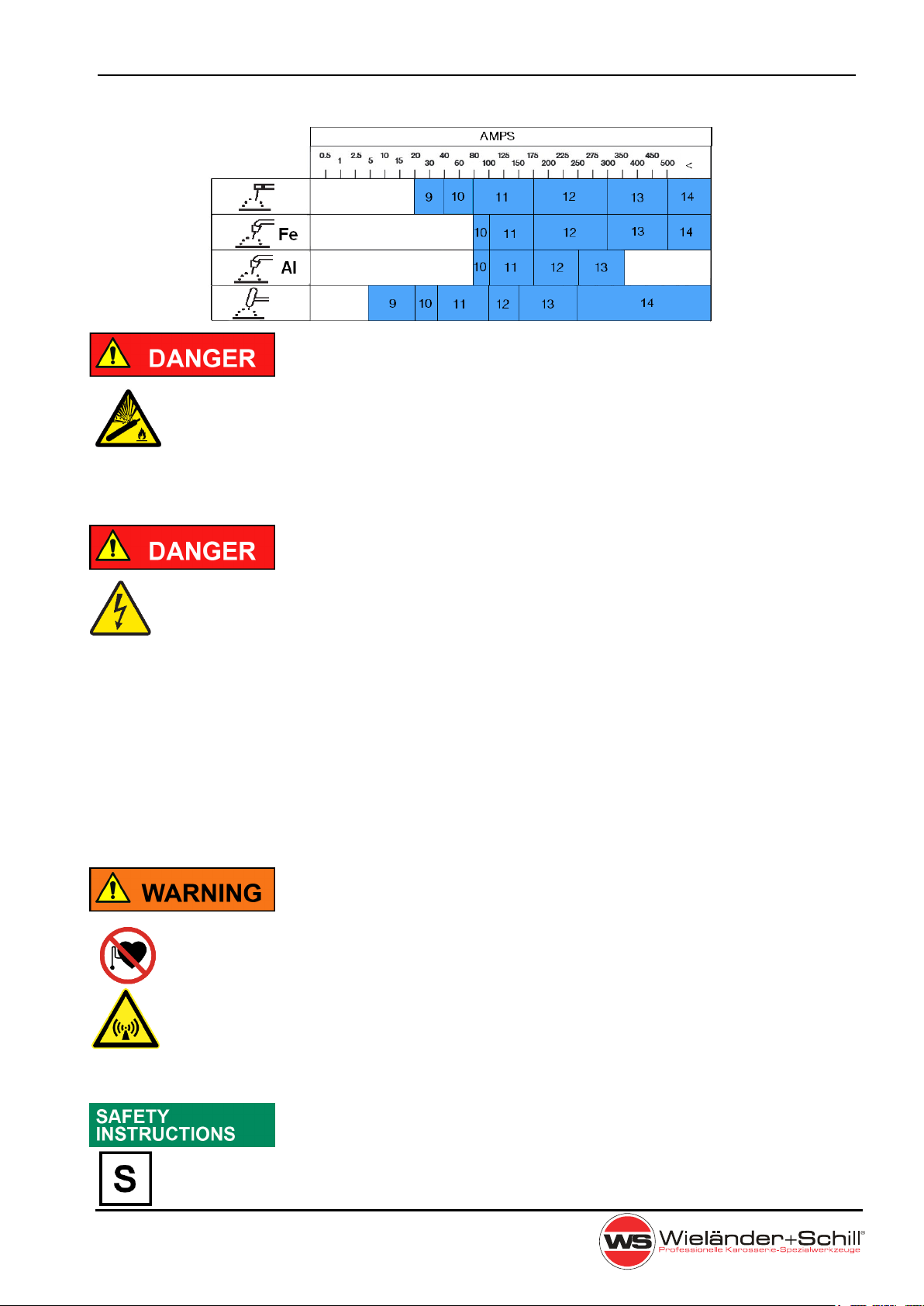
Recommended welding helmet lens shade according ISO 4850:
CYLINDERS CAN EXPLODE
Gas cylinders contain gas under high pressure which can explode
if damaged or exposed to a heat.
Regional safety regulations for pressurised gas must be followed.
Due to high pressure inside the bottles (up to 200 bar) it is
necessary to secure them against mechanical damage,
overturning, downfall, h
eating up (max 50°C), against sunshine
exposure for a longer time and against strong frost.
WARNING RISK OF ELECTRIC SHOCK
Voltages can cause potentially fatal electric shocks and burns on
contact. Even low voltages can cause a shock and lead to
accidents.
Install and ground this equipment according to the instruction
manual and in accordance with national and local standards.
Wear the full personal protective equipment (depending on the
application)!
Never touch live components such as welding current sockets or
stick, tungsten or wire electrodes!
Always place torches and electrode holders on an insulated
surface!
The device must be placed out of higher electrical danger
environment. You can be in the endangered environment with a
torch only.
CAUTION ELECTROMAGNETIC FIELDS
Device is constructed according IEC 60974-10 class A and is
intended to work only in industrial areas.
When operating welding machines, electro-magnetic interference
can occur.
The user is responsible for any interference caused by welding.
Pacemaker and hearing aid operation can be affected by magnetic
fields from high currents. Pacemaker and hearing aid wearers
should consult a doctor before going near any arc welding
machines.
Welding in the environment with higher electrical danger
The welding device is constructed in compliance with IEC 60974
as a device suitable for welding in the environment with higher
electrical danger.
Operation Manual InvertaPuls IP4-3
Page 11
4 OPERATION
4.1 Switching ON the machine
Always use the main switch on the back side of the machine to turn On and Off the device,
never use the power plug for this purpose!
4.1.1 Power-on sequence
After powered special power on sequence is started on the operating panel, to give the user
information about the firmware. First all segments are lighted up, than after following
information are displayed:
a)
Firmware type (in material Volt window)
EA – ACT panel
b)
Model (in Ampere window)
240
c)
Firmware revision (in Ampere window)
r11 major . minor revision numbers.
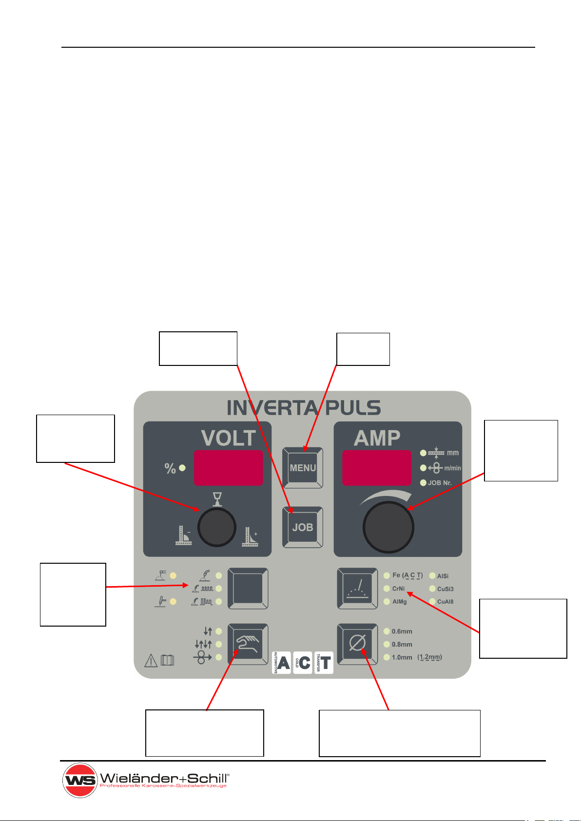
4.2 Operating Panel
4.4
JOB Mode
4.2.5
MENU
4.3.1
Welding
power
set up
4.3.2
Arc length
correction
4.2.2
Welding
process
selection
4.2.3
Filler wire
material
selection
4.2.1
Welding mode
selection
4.2.4
Filler wire diameter
selection

InvertaPuls IP4-3 Operation Manual
Page 12
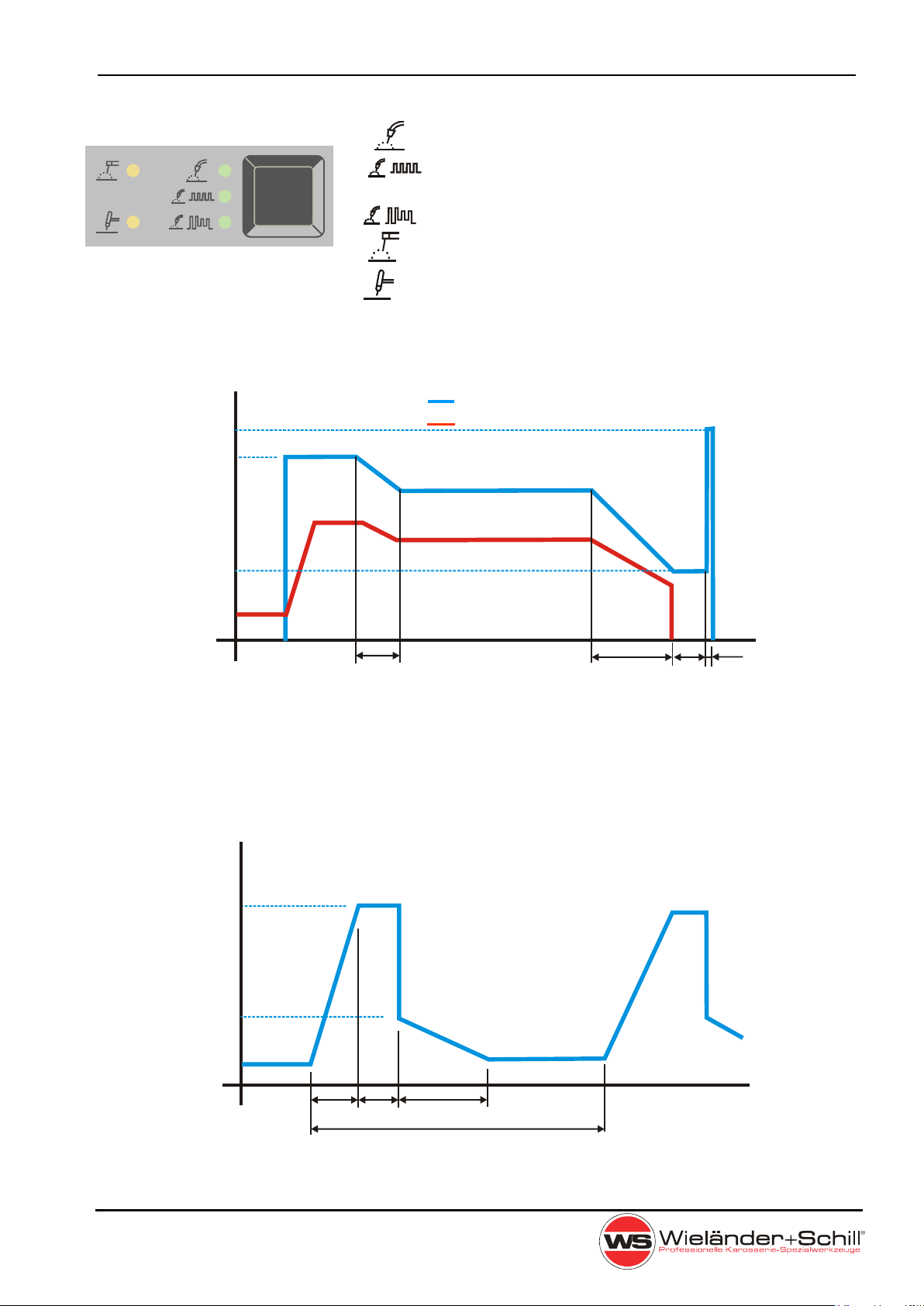
4.2.1 Welding mode selection
(Not available if MMA/TIG selected)
- 2- cycle mode
- 4- cycle mode
- Manual wire inch mode. In wire speed window is
possible to adjust the speed for manual feed. Feeding is
activated by pressing the trigger button.
2-TACT Mode / 4-TACT Mode
2-TACT/4-TACT relates to the function of starting button (trigger) on the welding torch.
Differences in operation of this two modes are shown in following pictures:
t
P
P
HOT
P
WELD
t
TRIGGER
2-TACT MIG/MAG operation
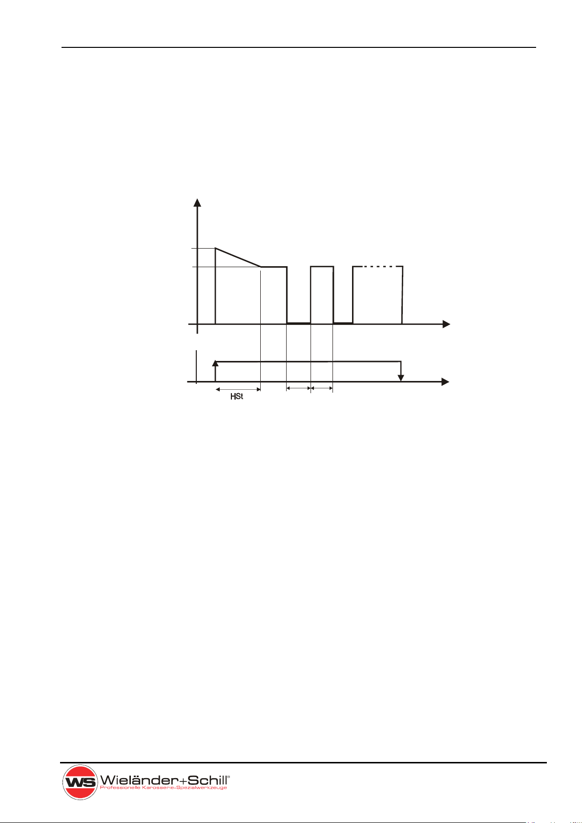
t
P
Hot start
level
Welding
Crater fill
level
t
TRIGGER
cFt
hSt
4-TACT MIG/MAG operation
Operation Manual InvertaPuls IP4-3
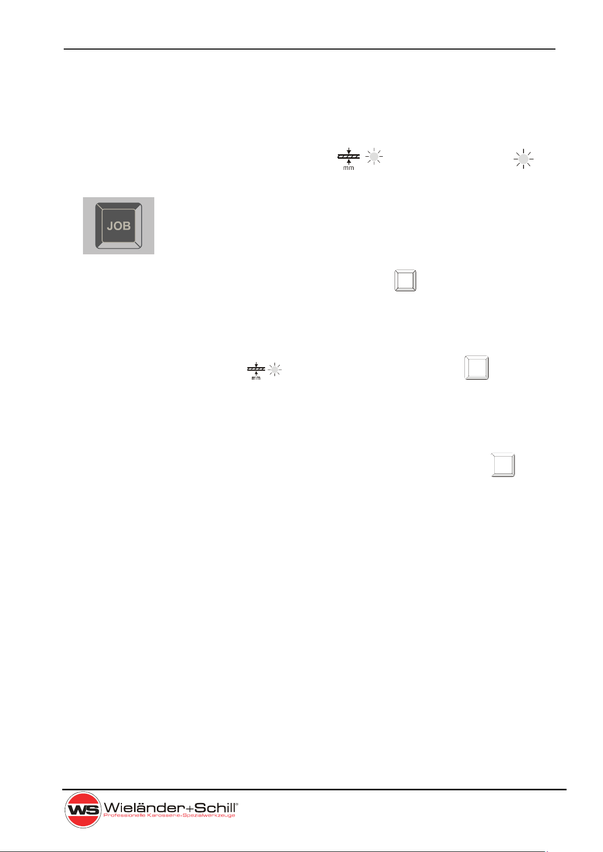
Page 13
Interval welding
To activate interval welding program, the pause time must be set greater than 0 (factory
setting). To disable interval welding feature, set the pause time parameter to 0 (menu
parameter number 1.9 – PAU). Interval function is available in both – 2cycle and 4cycle
operation
t
P
PHOT
PWELD
t
TRIGGER
PAu Act
2-TACT MIG/MAG operation
InvertaPuls IP4-3 Operation Manual
Page 14
4.2.2 Welding process selection
- Standard MIG/MAG welding process
- Pulsed MIG/MAG welding process (EcoPulse
only)
- MIG/MAG Double Pulse welding process
- MMA welding process
- WIG welding with Lift Arc ignition
Synergy parameters for MIG/MAG welding
hSL
hSt
Welding voltage
Wire speed
cSS
cFL
cFt
EPL
EPt
bbt
Time diagram of MIG/MAG weld
Synergy parameters for standard Pulse
Up
PL
bcL
FcL
PF
EPL
Prr PFr
Time diagram of Pulsed weld (without Hot start & Crater fill level)

Operation Manual InvertaPuls IP4-3
Page 15
MIG / MAG Double Pulse
Double pulse frequency –define a speed of interleaving hot and cold phases in double
pulse welding
Double pulse amplitude – power ratio between hot and cold phases in double pulse
welding
I
HOT
I
set
Frequency
Amplitude
Double pulse time characteristic
frequency
Amplitude
Double pulse weld – AlSi5 / 1.0mm wire
4.2.3 Selection of the additional material
(Not available if MMA/TIG selected)
Fe (ACT) - alloyed + non-alloyed steel, inert gas: 82%Ar + 18%CO2
(LED shines)
Fe (ACT) - Steel thin sheets ACT welding, inert gas: 82%Ar + 18%CO2
(LED flashes)
CrNi - Stainless steel AWS308LSi, gas: 87.5%Ar + 2.5%CO2
AlMg - Aluminum + magnesium, shielding gas: 100%Ar
AlSi - Aluminum + silicium, shielding gas: 100%Ar
CuSi3 - Copper silicium, shielding gas: 100%Ar
CuAl8 - Copper aluminium, shielding gas: 100%Ar

InvertaPuls IP4-3 Operation Manual
Page 16
4.2.4 Selection of the additional material diameter
0,6mm
0,8mm
1,0mm (1,2mm)
4.2.5 MENU
For enhanced adjustment is available MENU function.
Press and hold for 3 seconds

Operation Manual InvertaPuls IP4-3
Page 17
4.2.5.1 List of MENU parameters:
Display
Name
Description
Min.
Max.
Step
Unit
MIG
Pulse
MIG
Double
Pulse
MIG
MMA
TIG
GPr
Gas pre-flow time
0,0
10,0
0,1
sec
X X X - -
GPo
Gas post-flow time
0,0
10,0
0,1
sec
X X X - -
hSL
Hot-start level
100
199
1
%
X X X X -
cFL
Crater-fill level
1
100
1
%
X X X - -
hSt
Hot-start slope time
0,0
10,0
0,1
sec
X X X X -
cFt
Crater-fill slope time
0,0
10,0
0,1
sec
X X X - -
Act
Active time for interval weld.
0,0
10,0
0,1
sec
X X - - -
PAU
Pause time for interval weld.
0,0
10,0
0,1
sec
X X - - -
These parameters are reset to factory settings
when changing the material thickness selection.
Global menu parameters
Parameters that are independent of the selected filler material, wire diameter and base
material thickness are referred to as general parameters. All these parameters can be set by
the user in the menu. They remain saved and unchanged as long as the user does not
change the setting. The parameter group includes:
1. Gas pre-flow time
2. Gas post-flow time
3. Hot-start level – Hot start level in percent, based on the preselected
Welding current. Can only be> 100%.
4. Crater-fill level – Crater fill level in percent, relative to the selected one
Welding current. Can only be <100%
5. Hot-start slope time – a time which is needed to slope from hot start level to the
welding level. In sec.
6. Crater-fill slope time – a time which is needed to slope from welding level to the crater
fill level. In sec.
7. Active time – parameter for automatic interval welding, which defines an
active welding time in seconds
8. Pause time – parameter for automatic interval welding, which defines an
inactive time, when arc is off in seconds. If it is set to 0, interval
welding is disabled.
Synergetic controlled parameters

InvertaPuls IP4-3 Operation Manual
Page 18
4.3 Set up, adjustment and display description
4.3.1 Welding power set up
Teh welding-brazing machines are controlled with full
synergic feature (except Manual modus).
The welding power is to adjust just with one main rotary
encoder. By press of the encoder button, wire speed (in
meters/min) or material thickness (in millimeters) can be
selected.
In MMA and TIG mode is only Ampere setup possible.
4.3.2 Arc length correction synergic mode
In all MIG/MAG modes is possible to adjust length of
the welding arc. By turning the encoder in any direction
is display switching from Voltage mode to Arc length
correction mode (% LED active).
Arc length set to = 0 –
Arc length set to max. +
Arc length set to min. –
The settings made for the respective operating mode and
the additional material remain valid even after switching off
and on again!
Operation Manual InvertaPuls IP4-3
Page 19
JOB
JOB
4.4 JOB Mode
The JOB mode allows you to store up to 100 individual parameter settings in addition to the
preset programs.
Change from synergic mode to JOB mode JOB is
made
by short press of the JOB button . After entered the Job
mode, number of actual job is shown in the Material thickness / JOB
window. There are 100 jobs available: J00 – J99. By Turning main
encoder can be chosen required job number.
While in JOB mode, there are no set up and adjustments available
except the JOB number and welding mode. If adjustment is required,
JOB editing must be activated – see following section
To quit from JOB mode press JOB button JOB again.
4.4.1 Editing / saving the JOB
While working in synergic mode , by long pressing the JOB button actual set
up
can be stored. After long pressing of JOB button, number of job starts to flash. This number
can be changed by encoder rotation, after desired job number is set by pressing the
encoder button actual set up is saved under this job number.
To edit actual job, set job number to change, by long pressing the JOB button the
material thickness start to flesh and any change of any parameter can be made. After
changes are made, by short press of encoder button will be stored.
4.5 Selecting the active feeder
Active feed unit selection is indicated by LED indicator above the corresponding euro torch
connector. To switch the idle feed unit on, must be just pressed the trigger button on the
corresponding torch. By pressing the trigger button on the not active feed unit, it will switch
to active state with automatic up-loading of all appropriate settings on the front panel. After
releasing the torch button and pressing it again the welding process will start.
4.6 Parameters setup for different feed units
There can be made specific setup for each feed unit. All settings made on the front panel
are belonging to the active feed unit and will be stored in internal memory in case of
switching the feed unit to idle state or switching the machine off. Always if some setup
should be done, the feed unit must be set as active.

InvertaPuls IP4-3 Operation Manual
Page 20
4.7 ARC Control
If there is no arc detected for more than 3 seconds during active welding the inverter will be
automatically switched off.
This feature may prevent user from some desired actions. In case of feeding the wire in the
torch, please use Manual feed mode described before.
4.8 Factory setup
With the following procedure the machine can be reset to factory setup.
This procedure will delete all stored job an will reset all parameters to the state at delivery!
Make sure that the machine is conected to the power
supply and switched off.
Hold this button depressed and switch the machine on
until the initial display test sequence is over and the code
menu is displayed.
Once in the code menu you will have to enter the
unique code U 01, A 01, B 01, C 01. Individual
numbers can be accessed by pressing voltage
encoder.
When you have entered all 4 numbers and you are sure
that they are correct then confirm the complete code by
depression of this button. The panel will be restarted in
order to apply new factory default settings.
Table of contents
Other WIELANDER+SCHILL Welding System manuals


Popular Welding System manuals by other brands


Ter Welding
Ter Welding Multi 250K instruction manual

STEINEL PROFESSIONAL
STEINEL PROFESSIONAL HG Roof Information

Lincoln Electric
Lincoln Electric RANGER 305 D CE Specification sheet

CARBONE
CARBONE Digi-Tig320ACDC Operator's manual

RODEX
RODEX RDX5128 instruction manual

Hypertherm
Hypertherm HT2000LHF instruction manual


