WIELANDER+SCHILL IM 240-i User manual

MV Marketing und Vertriebs-GmbH & Co. KG
Professionelle Karosserie-Spezialwerkzeuge
Siederstr. 50 D-78054 Villingen-Schwenningen Tel. +49 (0) 7720 8317 0 E-mail inf[email protected]
sb-06/2014
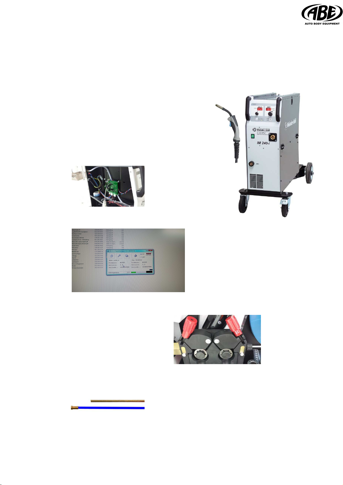
MIG/MAG IM 240-i
welder with inverter technology
A very straight forward and simple to use machine with
simple settings because of the tough construction
- it will tolerate very hard impacts.
Technical Data
•MIG/MAG welding (MIG-flux-cored welding wire brazing)
•4 roller drive with trim adjustment
•Use with D300 wire spool (max. 17 kg)
•Display with hold function for
welding current and tension.
•Dynamic pulse adjustment to remove
the „ball“ at the end of the wire
•Extremely good welding results even on very thin sheet
metal. There are no problems with steelwelding on panels
as thin as 0,6mm
(0,023 in)
Content of delivery
Welder with rollers
Torch MB 15, 3m
Earth cable 4 m
Item No 341290
Mains connection 220/240V - 50/60 Hz
Load capacity (delayed) 16 A
Current adjustment range 20 - 200A
Voltage adustment range 10 - 35V
Welding range/steps continuous
No load output voltage Uo @40°C 20%/200A/24V
Load capacity 60% ED@40°C 140A / 21V
Load capacity 100% ED@40°C 120A / 20V
Weight 35 kg
Dimensions (HxBxL) 890x365x600 mm
single phase
220/240V
IM 240 I - steel wire 0,6 mm
Upgrade
1. Software
•New software PD board
•Version EC200_14.hex
•
Open lid at the left side of the welder casin .
2. Transport wheels 0,6 mm
3. Wheel pressure +/- 2,5
4. Torch with Teflon liner blue inner diam. 0,8 mm (max)
Weldin nozzle 0,6 mm
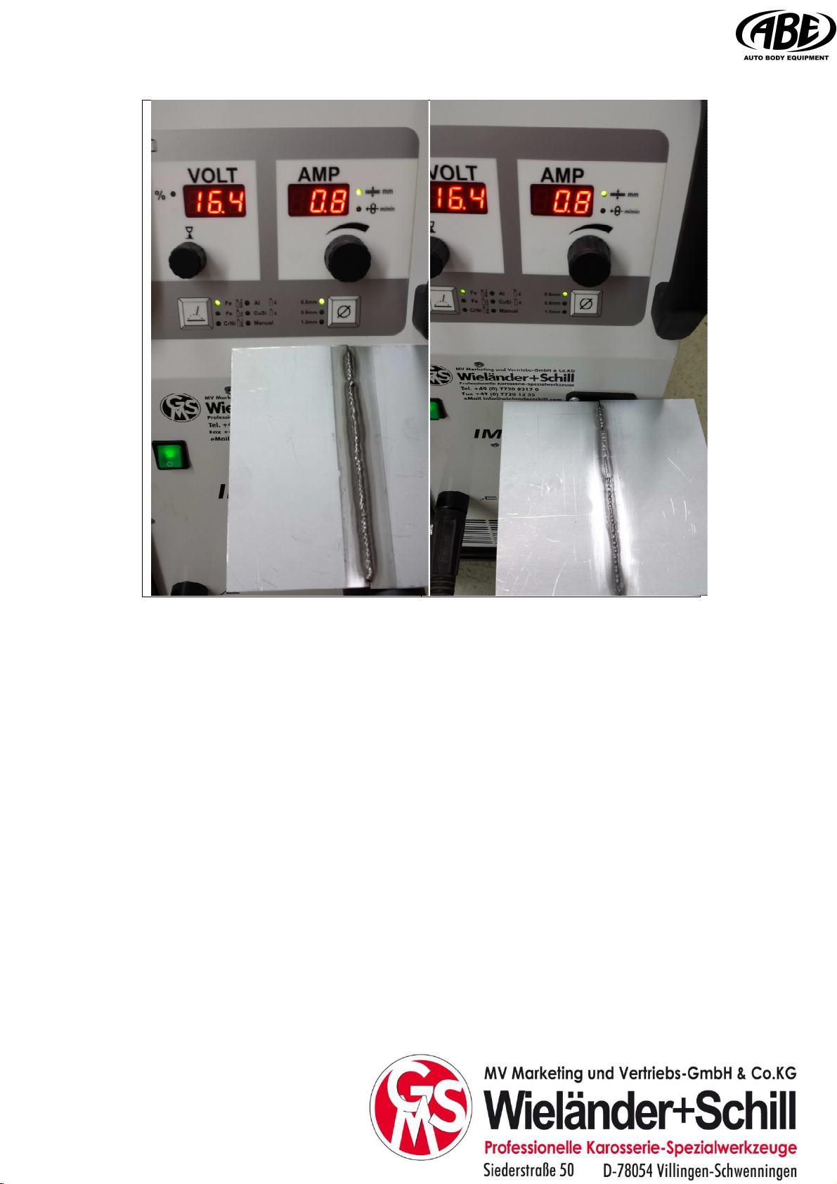
PERFEKT weldin performance IM 240 I with weldin wire
SG 2 0,6 mm / as 80/20 / nozzle 0,6 mm
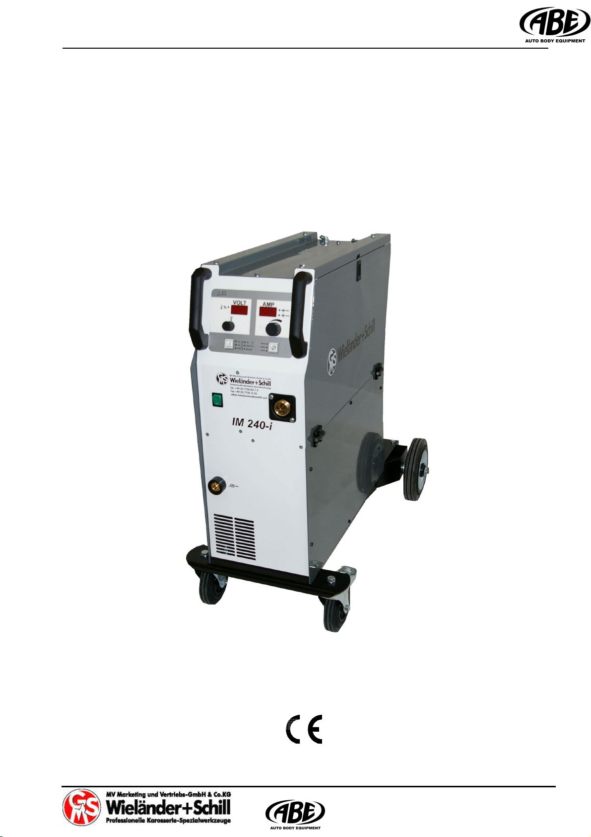
Operation manual IM 240-i
Page 1 of 15
Operation manual
IM 240-i
August 2014
REV 2.1

IM 240-i Operation manual
Page 2 of 15
CONTENT
1PREFACE ...................................................................................................................... 4
1.1 PRODUCT INTRODUCTION ........................................................................................... 4
1.2 ASSEMBLY REQUIREMENTS ......................................................................................... 4
2PUTTING INTO OPERATION ........................................................................................ 5
2.1 CONNECTING TO THE ELECTRIC NETWORK.................................................................... 5
2.2 CONNECTING THE PRESSURE BOTTLE CONTAINING PROTECTIVE GAS .............................. 5
2.3 CONNECTING THE RETURN CABLE................................................................................ 5
2.4 MIG/MAG TORCH ..................................................................................................... 6
2.5 SELECTING THE FEEDING WHEEL ................................................................................. 6
1.1 PLEASE CHOOSE THE FEEDING ROLLS CORRESPOND TO USED WELDING WIRE. ................ 6
2.6 WELD AREA PREPARATION .......................................................................................... 7
3SAFETY AND FIRE INSTRUCTION .............................................................................. 7
3.1 PROTECTION ............................................................................................................. 7
3.2 REMOVING THE FIRE HAZARD ...................................................................................... 7
3.3 HANDLING THE PRESSURE BOTTLES............................................................................. 8
3.4 PROTECTION AGAINST ELECTRICAL ACCIDENTS............................................................. 8
3.5 EXTRAORDINARY MENACE DURING WELDING................................................................. 8
4OPERATION .................................................................................................................. 9
4.1 TURNING THE DEVICE ON ........................................................................................... 9
4.1.1 Power-on sequence ......................................................................................... 9
4.2 OPERATING PANEL..................................................................................................... 9
4.2.1 Filler wire material selection ............................................................................. 9
4.2.2 Filler wire diameter selection .......................................................................... 10
4.3 SET UP, ADJUSTMENT AND DISPLAY DESCRIPTION ....................................................... 10
4.3.1 Synergic mode ............................................................................................... 10
4.3.2 Manual mode.................................................................................................. 11
5CARE AND MAINTENANCE ....................................................................................... 12
5.1 DISPOSAL OF THE MACHINE....................................................................................... 12
6TECHNICAL DATA ...................................................................................................... 13
7TROUBLESHOOTING ................................................................................................. 14

Operation manual IM 240-i
Page 3 of 15
Wieländer + Schill, MV Marketing und Vertriebs GmbH & Co. KG
Siederstrasse 50
DE-78054 Villingen-Schwenningen
Telefon (+49) 07720-8317-0 Telefax (+49) 07720-8317-95
e-mail: info@wielanderschill.com http:// www.wielanderschill.com
EG-Konformitätserklärung
Hersteller / Bevollmächtigter:
MAHE Gerätebau GmbH
Auwiese 12
D-57223 Kreuztal-Kredenbach
Bevollmächtigte Person,
für die Zusammenstellung der technischen
Unterlagen:
Ing. Jaroslav Kučera
Štefánikova 1
059 21 Svit
SLOVAKIA
Produkt: IM 240-i
Hiermit erklären wir, dass die oben beschriebene Maschine allen einschlägigen Bestimmungen der
Maschinenrichtlinie 2006/42/EG entspricht.
Die oben genannte Maschine erfüllt die Anforderungen der nachfolgend genannten Richtlinien und
Normen:
EN 60974-1
Sicherheitsanforderungen für Einrichtungen zum Lichtbogenschweißen
Teil 1 Schweißstromquellen
EN 60974-5
Lichtbogenschweißeinrichtungen
Teil 5 Drahtvorschubgeräte
EN 60974-10
Elektromagnetische Verträglichkeit (EMV) - Produktnorm für
Lichtbogenschweißeinrichtungen
EN 60309-1
Stecker, Steckdosen und Kupplungen für industrielle Anwendungen
Teil 1: Allgemeine Anforderungen
EN 60309-2
Stecker, Steckdosen und Kupplungen für industrielle Anwendungen
Teil 2: Anfonderungen und Hauptmaße für die Austauschbarkeit von Stift- und
Buchsensteckvorrichtungen
Kreuztal, 12.11.2012
Mario Mankel, Manager

IM 240-i Operation manual
Page 4 of 15
1 PREFACE
Dear customer!
Congratulation to purchasing of this quality inverter welding machine. Please read whole
Operation manual before you start.
1.1 Product introduction
IM 240-i welding machine is compact MIG-MAG welding inverter especially developed for
car body repair. Its excellent brazing characteristic as well as good steel welding possibilities
enables to use this device to repair all kinds of vehicles with fine quality results.
Be aware of danger resulted from welding and follow the safety and fire instructions (see the
Part 7).
It is necessary to keep the device on a dry place, to protect device against moisture. It is not
advisable to use the device on the open air during rain.
1.2 Assembly requirements
It is necessary to set the device for welding in protection atmosphere on a dry place with the
sufficient area for cooling. The device is designed for use in covered area (under roof).

Operation manual IM 240-i
Page 5 of 15
2 PUTTING INTO OPERATION
2.1 Connecting to the electric network
Check if the voltage stated on the device label complies with rated voltage of alternate volta-
ge of your electric network.
The device can be connected to electric socket equipped with protective contact installed by
authorized electrician (TN system according IEC 60364). Current circuit of socket must be
protected with 16Amp melting safety fuse or circuit breaker.
The device is delivered with plug according to CEE standard. For other connections remove
delivered plug and use certified plug according national standard.
230V Supply 110V Supply
Net wire color Net wire color
L Brown L1 Brown
N Blue L2 Blue
PE Yellow/green PE Yellow/green
2.2 Connecting the pressure bottle containing protective gas
Make sure You are using right gas according welded material (see part 3.3.5)
Set the pressure bottle to the stand intended for it and fasten it by belt to the holder on the
back side of the device. Open a cover and after that open the bottle valve for a short time in
order that the gas flows away from your body. Screw a reduction valve on the pressure
bottle. Connect a hose to the MIG-MAG welding device reduction valve. The recommended
gas flow is 8 – 15 liter/minute in a room without draft.
If you use an adjustable reduction valve, you can adjust a gas flow with a wing nut with
a liter scale. The device must be turned on and Gas-check function activated the welding
button must be pressed during adjustment.
It is not allowed to repair pressure valves. It is necessary to send the defective reduction val-
ves to service.
2.3 Connecting the return cable
It is necessary to connect the grounding clamp in the very vicinity of welded place. The
transfer contact must be metallic clear free of dust and color.

IM 240-i Operation manual
Page 6 of 15
2.4 MIG/MAG torch
For torch connecting is used EURO Standard torch connector.
Please, tighten the connector well to eliminate the conduction losses. A loose connection
can cause damage of the machine and torch.
Never use damaged torch!
Make sure the contact tip match the manufacturer’s recommendations for type and diameter
of used wire. Connect the welding conduction main connecting plug into the main socket on
the front side. Secure it with the lock nut.
In case Teflon liner is used is it necessary to use contact neck liner out of brass to provide
good current conduction to the fill wire.
2.5 Selecting the feeding wheel
Please choose the feeding rolls correspond to used welding wire.
Materials Shape φOrdering Nr.
0.6/0.8mm E017100008
0.8/1.0mm E017100015
Fe, SS
1.0/1.2mm E017100018
1.0/1.2mm E017100010
Al
1.2/1.6mm E017100017
Fe, MC, FC
1.0/1.2mm E017100055
Pressure
adjustment
Feeding
rolls
Fixing
points

Operation manual IM 240-i
Page 7 of 15
2.6 Weld area preparation
A work piece must be clean in the welding area, free of paint, metallic coat, dirt, rust, fat and
moisture. The preparation of weld must be according to technical instructions for welding.
3 SAFETY AND FIRE INSTRUCTION
Keep this device out from children. You have to follow the safety and fire instruction when
you work with welding device for welding in protective atmosphere. Regulations for preven-
ting of accidents during "welding, cutting and similar working activities".
3.1 Protection
A welder should wear a closed and dry working dress (non-flammable welding dress is the
best), firm insulating shoes (jackboots), cap and leather sleeve gloves.
- Clothing made from synthetic materials and half shoes are improper.
- Insulating gloves on the both hands protect against electricity (welding circuit no load run),
harmful radiation (heat and U.V. radiation), and also against flaming metal and slag drops.
The effect of U.V. radiation on the uncovered body parts is similar as sunburn.
It is necessary to wear an appropriate eye protection against sparks, heat, visible and invi-
sible radiation (protective shield or protective helmet equipped with protective glass from the
10-th to 15-th grade according to DIN 4647 standard, depending on used current).
- Do not look into an electric arc with unprotected eyes (you can go blind or you can burn).
Invisible U.V. radiation causes a very painful eye conjunctiva inflammation without eyes
protection, which rises even after couple of hours.
- Weld nearby the other persons, which are able to help you fast in a case of emergency. .
- The persons or assistants present nearby an electric arc have to be advised about hazard
and must be equipped with a necessary protective equipment.
- A working places situated in the neighborhood have to be protected with proper shields
against radiation.
- It is necessary to ensure air supply and exhaustion in closed rooms and buldings. The toxic
vapors evaporate from metal coats and anticorrosive paints due to heat from the electric
arc during welding.
3.2 Removing the fire hazard
Follow this instructions before welding starts:
- Remove inflammable materials and objects in 5 meter ring from the welding place.
- The inflammable materials and objects which could not be removed must be protected by
covering with steel plates, wet rags etc...
- It is necessary to cover or tighten the holes, cracks in walls etc... due to uncontrollable
sparking.
- Prepare the fire extinguisher, bucket of water etc...

IM 240-i Operation manual
Page 8 of 15
- Be conscious of possibility of hidden fire on covered objects or in another rooms due tu
heat transfer.
- After finishing of welding check up the welding place for smoking parts or small fires in
the time interval up to 6 or 8 hours.
3.3 Handling the pressure bottles
You have to follow respective safety regulations (technical regulations for pressure gas TRG
253 and 303).
Due to high presure inside the bottles (up to 200 bar) it is necessary to secure them against
mechanical damage, overturning, downfall, heating up (max 50°C), against sunshine expo-
sure for a longer time and against strong frost.
- When the MIG/MAG device is being equipped with pressure bottle, you have to keep on
mind that the bottle could cause overturn of device on an uneven surface. To prevent this
kind of accident you should use an appropriate pressure bottles.
- Filling of the bottles is allowed only by specialized companies.
3.4 Protection against electrical accidents
It is not allowed to carry the torch under armpit or to hold it in such way, that a current could
flow through human body. The device must be turned off during the longer breaks. When
the welding is finished and before moving, the device must be un-plugged from the power
supply. It is necessary to cut immediately off the power supply in a case of accident.
To prevent uncontrollable welding back current you have to connect the welding supply di-
rectly to the work piece by working clamp. The pipes, steel constructions etc... must not be
„electric conductors“ in any case, if they are not welded themselves.
Follow this instructions in any case:
The welding current must not have any conductive connection with protective or zero con-
ductor of the power supply network. Because the protective contact of power supply is con-
nected to welding device, you must not put the grounding clamp down on the welding device
body, when the device is connected to power supply network. The workpiece must be
insulated from power supply protective and zero conductor and from the grounding con-
ductor.
3.5 Extraordinary menace during welding
- It is not allowed to weld in the rooms with increased danger of fire or explosion. The special
regulations must be followed in this areas.
- It is not allowed to weld in the tanks for gas, fuel, oil, paint etc..., even if they are empty for
a long time. The remnant of content could cause an explosion.
- The welds exposed to an extraordinary strain must comply to strict safety regulations and
can be welded only by trained and examined welders (e.g. pressure tanks, rails, drawing
devices for cars, supporting structures).

Operation manual IM 240-i
Page 9 of 15
4 Operation
4.1 Turning the device ON
Always use the main switch to turn On and Off the device, never use the power plug for this
purpose!
4.1.1 Power-on sequence
After powered special power on sequence is started on the operating panel, to give the user
information about the firmware.
a) Firmware type (in voltage window)
Fm – Front panel IM
b) A mperage rating (in Ampere window)
200 – 200Amp
c) Firmware revision (in Ampere window) r11 major . minor revision numbers.
4.2 Operating Panel
4.2.1 Filler wire material selection
FeSg2 (MIX) - Standard, not alloyed steel,
shielding gas: 82%Ar + 18%CO2
FeSg2 (CO2) - Standard, not alloyed steel,,
shielding gas: 100% CO2
CrNi - CrNi steel AWS: 308Lsi
shielding gas: 2.5% CO2+ 87.5%Ar
Al - Aluminum + 5% magnesium AlMg5,
shielding gas: 100%Ar
Cu - Copper silicium wire CuSi3
shielding gas: 100%Ar
Manual - Manual setup of wire speed and welding voltage
IM 240-i Operation manual
Page 10 of 15
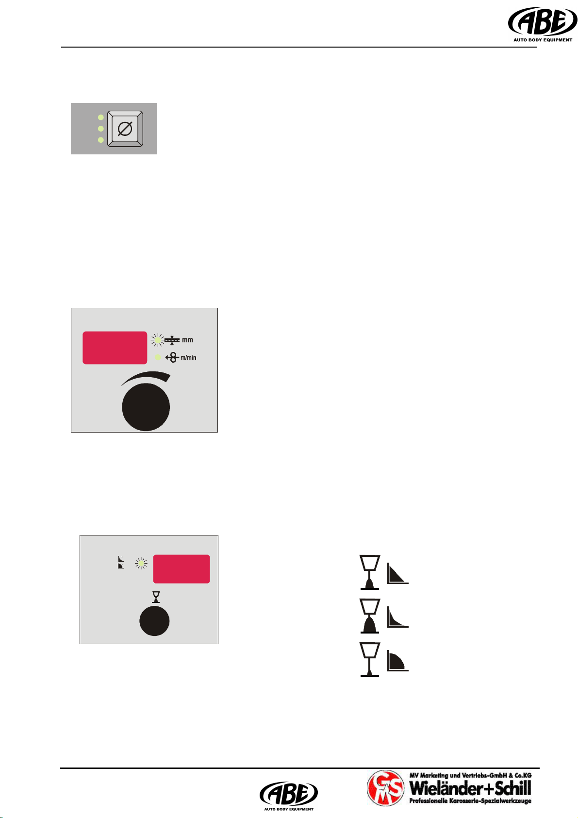
4.2.2 Filler wire diameter selection
(Not available if MMA/TIG selected)
0,6mm
0,8mm
1,0mm (0.9mm in case FC material selected)
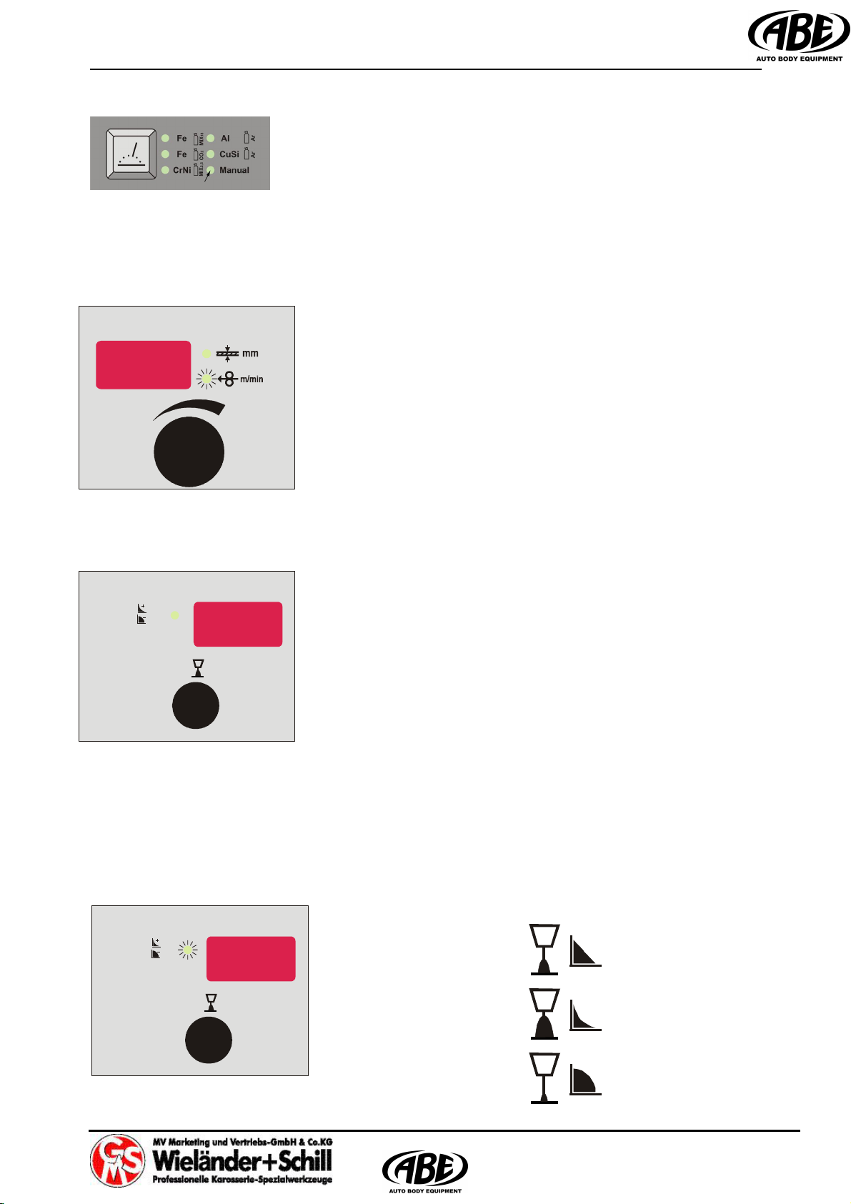
4.3 Set up, adjustment and display description
4.3.1 Synergic mode
4.3.1.1 Welding power set up
IM 240-i machines can be controlled with full synergic
feature. The welding power is to adjust just with one main
rotary encoder. By setup of material thickness (in
millimeters) are automatically set all welding parameters .
4.3.1.2 Arc length correction
There is possible to adjust length of the welding arc. By
turning the encoder in any direction is display switching from
Voltage mode to Arc length correction mode (% LED
Active).
A rc length set to 0 –
Arc length set to +30 –
Arc length set to –30 –
0.8mm
0. mm6
10.mm
AMP
%
V
OLT
Operation manual IM 240-i
Page 11 of 15
4.3.2 Manual mode
4.3.2.1 Wire speed setup
Set up wire feed speed in m/min by turning the encoder.
4.3.2.2 Welding voltage setup
Set up the welding voltage in Volts by turning the encoder.
4.3.2.3 Arc length correction
There is possible to adjust length of the welding arc. By
turning the encoder in any direction is display switching from
Voltage mode to Arc length correction mode (% LED
Active).
A rc length set to 0 –
Arc length set to +30 –
Arc length set to –30 –
%
V
OLT
AMP
%
V
OLT

IM 240-i Operation manual
Page 12 of 15
5 CARE AND MAINTENANCE
Pull out the power cable from the socket before every maintenance and troubleshooting.
The device is almost maintenancefree.
It is necessary to check feeding wheel, pressure roller and inflow nozzle regularly, if there is
not some dirt. If it is, you have to clean it out.
Please, change the contact tip on the torch regulary
The complete set of pressure hoses should be cleaned up from time to time, because of em-
bedded dust and parts.
The contact nozzle of the torch is wearing up subsequently. When the hole in the nozzle is
too large, it is necessary to change the nozzle. The metal drops are embedding in the inner
walls of the torch cover. Take them out if necessary. The separator is helpful and it is also
a prevention against the firm caking of the drops.
You have to change the damaged cables at once.
5.1 Disposal of the machine
Do not dispose of electrical equipment together with the normal waste!
In observance of European Directive 2002/96/EC on Waste Electrical
and Electronic Equipment and its implementation in accordance with
national law, electrical equipment that has reached end of its life must
be collected separately and returned to an environmentally compatible
recycling facility.

Operation manual IM 240-i
Page 13 of 15
6 TECHNICAL DATA
Mains connection 1~ 230V +10/-15%
Mains cable 3x2.5qmm
Fusing 16Amp delayed
Load capacity 20% @200Amp/24V
60% @140Amp/21V
100% @ 120Amp/20V
Peak input current I1p 32Amp @200Amp/24V
Effective maximum input current I1eff 15Amp @200Amp/24V/20%
No load output voltage Uo 40.2
Efficiency 87%
Power factor 0.75
Current adjustment range 20 – 200Amp
Voltage adjustment range 10 – 35V / 0.1V step
Wire speed range 1.5 – 15 m/min
Wire feed roll diameter 37mm
Wire spool diameter 300mm max / 17kg max
Thermal class H(180°C)
Temperature range -10 ….+40°C - operating temp.
-40 ….+80°C - storage temp.
Dimensions LxWxH 900x500x840mm
Weight 40kg
Degree of protection IP23

IM 240-i Operation manual
Page 14 of 15
7 TROUBLESHOOTING
Mechanical defects are mostly the result of irregular wire feeding or its blocking.
Electrical defects cause partial or full device failure. Only an authorized electrician can repair
the electrical part of welding device.
The trobleshooting should be executed in the OFF mode first and in the following sequence:
- Check up the solidity of electrical connections on switches, current transformer, suppressor
and also the solidity of plugged and soldered connections.
- Check up the conductivity and fuse contacts.
- Check up visually possible short circuits or winding overload (coloration).
Possible malfunction Troubleshooting
Possible reason
Electric arc is irregular or unstable
1. wrong welding voltage setup adjust the voltage
2. too much/little wire adjust the wire feed regulator
3. The workpiece clamp is loose make a good contact between workpiece
or transfer resistance is too high (rust, and clamp
paint)
4. The contact nozzle is worn up or change it
the diameter is wrong
5. The gas flow is not correct adjust the gas flow
6. The workpiece is not clear in the welding remove paint, rust, fat etc.
area
7. Performance grade malfunction take the device to service
8. Plug-in spiral is dirty clean it up or change it
9. Feeding malfunction see thereinafter
Too much metal drops during welding
1. too much wire adjust the wire feed regulator
2. welding voltage is too high set up lower voltage
3. workpiece is dirty clean it up
Feeding engine is not rotating
1. Power malfunction check up the connection to the socket
2. Button on the torch was not pressed press the button
3. Fuse change it (must be changed by authorized
electrician)
4. Engine malfunction take the device to service

Operation manual IM 240-i
Page 15 of 15
Wire feeding malfunction
1. Pressing roller is loosen Increase the pressure to the leaf spring by
using the grooved screw
2. Wire has got out from feeding Center the intake nozzle
3. Wire feed wheel grove is worn up Change the wire feed wheel
4. Wire is welded to the contact nozzle Change the contact nozzle, if the wire is
deformed, lower the pressure on wire
Device turns OFF and the “Err tMP” is displayed
1. Time of make is exceded (TM) Let the device cool down and folow the
instructions for TM according to device type
The protective gas still flows
1. Magnetic valve is dirty and it is still open Disconnect the torch connector and
connecting hose, alternately flow a pressure
air into the torch connector and connecting
hose and in the same time often press the
button on the torch.
Only an authorized electrician can repair the eletric part of device.

W
W
Wi
i
ie
e
el
l
lä
ä
än
n
nd
d
de
e
er
r
r
u
u
u.
.
.
S
S
Sc
c
ch
h
hi
i
il
l
ll
l
l
M
M
MI
I
IG
G
G-
-
-B
B
Br
r
ra
a
az
z
zi
i
in
n
ng
g
g
S
S
Se
e
em
m
mi
i
in
n
na
a
ar
r
r
STR 02-08 - page 1
MIG-Brazing is a kind of soldering technique using: a welding arc together with a
special area protection gas.
push position
What kind of material you can braze?
All kind of steel plates, either coated or uncoated, such as zinc ~, phosphate ~ or
aluminium coat.
The advantages of MIG-Brazing:
•The melting temperature is around 900 -1.000 oC. Therefore there is far less
damage to the zinc coating next to the area you are working
•Ot zinc coated sheet metal less smoke and less pores in the area
•Less temperature means less damage through heat distortion
•Less risk of corrosion in the area
•Brazing is much easier to grind, consuming less ~discs, files and grinding-paper
The disadvantages of MIG-Brazing:
•Brazing wires and argon gas are more expensive
•Sheet metal has to be clean, no paint, no factory primer
•Sheet metal has to be flush and close to each other. No distance in between.
MIG-Brazing gas:
•Inert gas Argon 100 % (4.5 and higher) or Argon + 02(99%+1%)
MIG-Brazing wires approved by car makers:
•CuSi3 (0,8mm + 1,0mm)
•CuAl8 or CuBzAl8 (0,8mm + 1,0mm)
Current nozzle + MIG Brazin
g
wire
gas nozzle
protection gas
Argon 4.5
preheat and
evaporations of
the zinc in front

W
W
Wi
i
ie
e
el
l
lä
ä
än
n
nd
d
de
e
er
r
r
u
u
u.
.
.
S
S
Sc
c
ch
h
hi
i
il
l
ll
l
l
M
M
MI
I
IG
G
G-
-
-B
B
Br
r
ra
a
az
z
zi
i
in
n
ng
g
g
S
S
Se
e
em
m
mi
i
in
n
na
a
ar
r
r
STR 02-08 - page 2
bottom: so-called the root
The differences between MIG-Brazing and steel welding
Using the MIG-Brazing the base material never gets into liquid conditions different to
welding with steel wire and Mixgas or CO2gas.
Mixgas = Argon/CO2 80/20, 82/18, 85/15 % = soft, no sparks, little root, especially for thin sheet metal
CO2gas = 100% = very hot, sparks, deep root, preferred for thick steel
MIG-Brazing: the sheet metal will not become one with the brazing material. Steel
requires around 1.400oC to meld, to become liquid. As brazing is around 900oC, the
two materials left and right will stay in their shape.
Therefore it is very, very important to have a certain gap between the sheet metal so
the braze is able to penetrate in between. At the end of the job there must be a
reasonable top and bottom overlap. Some people call the overlaps also: mushroom
Steel welding with so-called MAG-wire gets hot up to 1.400-1.500 oC. At the end the
sheet metal and the wire become one.
Brazing needs: a gap between the sheets. The most important thing in brazing is
to respect a specified gap between the sheet metal if you work in butt weld
position. F.i. if you do side panel repairs.
In no visible areas, such as inner wheel house or chassis legs do not grind off the
top overlap. Just keep it and your repaired area gets even stronger. The bottom root
make sure it is big enough, at least two times the size of the material.
li
q
uid braze li
q
uid weldin
g
wire
material liquid melted area
top: overlap
Other manuals for IM 240-i
1
Table of contents
Other WIELANDER+SCHILL Welding System manuals


Popular Welding System manuals by other brands

Mi-T-M
Mi-T-M AGW-SV14-B Operator's manual

Arc-Zone
Arc-Zone Piranha 3 Operation manual

Oerlikon
Oerlikon CITOTIG 240 AC/DC Safety Instructions for Operation and Maintenance

Linde
Linde MSI 350 puls Kompakt operating instructions

EWM
EWM Picomig 305 puls TKM operating instructions

Lincoln Electric
Lincoln Electric Mobiflex 400-MS Specification sheet


Arcoweld
Arcoweld Arcostick MMA 130 Operation manual

TECH A V
TECH A V GMAW Learner Guide

Chicago Electric
Chicago Electric Dual Mig 151T-1 36692 User and maintenance manual

Solaris
Solaris BLSA3 Instruction and reference guide

HTP
HTP MTS 160 owner's manual

Miller Electric
Miller Electric Big 40 Diesel Specifications