Wigersma & Sikkema UNIGAS 300 User manual

Installation and operating manual
CI-module UNIGAS 300
Installation and operating manual CI-module UNIGAS 300
DDG6010MHEN/09-2023/Rev.A5 1
All rights reserved.
Copyright © 2023 Wigersma & Sikkema B.V.
All the figures and descriptions in this installation and operating manual have been compiled only after careful
checking. Despite this, however, the possibility of errors cannot be completely eliminated. Therefore, no
guarantee can be given for completeness or for the content. Also, the manual cannot be taken as giving
assurance with regard to product characteristics. Furthermore, characteristics are also described that are only
available as options.
The right is reserved to make changes in the course of technical development. We would be very grateful for
suggestions for improvement and notification of any errors, etc.
With regard to extended product liability the data and material characteristics given should only be
taken as guide values and must always be individually checked and corrected where applicable. This
particularly applies where safety aspects must be taken into account.
Further support can be obtained from the branch or representative responsible for your area. The address is
printed on the back of this manual or simply enquire at Wigersma & Sikkema B.V.
Passing this manual to third parties and its duplication, in full or in part, are only allowed with written permission
from Wigersma & Sikkema B.V.
Preface
◼This manual provides important information about the use of the CI-Module. Please read this manual
carefully.
◼Various remarks and warnings in this manual are marked with symbols. Read these carefully and
take measures were necessary.
The symbols used have the following meaning.
REMARK
Suggestions and recommendations to make tasks easier.
NOTE
A note draws user's attention to potential problems.
WARNING
If the procedure is not carried out correctly, a dangerous situation may
develop, or data or settings may be lost.
The guarantee becomes invalid if the product described here is not handled properly, repaired or modified by
unauthorized persons or if replacement parts are used which are not genuine parts from Wigersma & Sikkema
B.V.

Installation and operating manual CI-module UNIGAS 300
DDG6010MHEN/09-2023/Rev.A5 2
Table of contents
1Introduction CI module UNIGAS 300......................................................................... 3
2Installing the CI-module............................................................................................. 4
3IDOM............................................................................................................................ 5
3.1 Data structure ...................................................................................................................................... 5
3.2 Data format.......................................................................................................................................... 5
3.3 IDOM settings...................................................................................................................................... 5
4FTP messages............................................................................................................. 6
4.1 Start FTP ............................................................................................................................................. 6
4.2 First FTP message .............................................................................................................................. 6
4.3 FTP file................................................................................................................................................. 6
4.4 XML file format..................................................................................................................................... 7
4.4.1 XSD................................................................................................................................................ 7
4.5 IEC 62056-21 file format...................................................................................................................... 8
4.6 CSV file format..................................................................................................................................... 8
4.7 FTP settings......................................................................................................................................... 8
5Modbus........................................................................................................................ 9
5.1 Introduction:......................................................................................................................................... 9
5.2 Modbus Registers.............................................................................................................................. 10
5.3 Data types.......................................................................................................................................... 12
5.3.1 Ushort........................................................................................................................................... 12
5.3.2 ULONG ........................................................................................................................................ 12
5.3.3 Counter ........................................................................................................................................ 13
5.3.4 BCDDate...................................................................................................................................... 13
5.3.5 BCDNO........................................................................................................................................ 13
5.3.6 BCDNO3...................................................................................................................................... 13
5.3.7 BCDNO4...................................................................................................................................... 14
5.3.8 IEEEFLOAT ................................................................................................................................. 14
5.3.9 HEX2............................................................................................................................................ 15
5.4 Read out examples............................................................................................................................ 16
5.4.1 Register 1 -7 ................................................................................................................................ 16
5.4.2 Register 101 -104 ........................................................................................................................ 16
5.4.3 Register 301 –324....................................................................................................................... 17
5.4.4 Register 327 –351....................................................................................................................... 17
5.4.5 Register 501 –506....................................................................................................................... 18
5.4.6 Register 801 -812 ........................................................................................................................ 18
5.4.7 Register 813 –820....................................................................................................................... 19
5.4.8 Register 822 –833....................................................................................................................... 19
5.5 Device identification........................................................................................................................... 20
6Parameters.................................................................................................................21
7Recognition of modules installed in UNIGAS 300 ..................................................23
8UNITOOL and CI module...........................................................................................23
9Appendix 1; Specification.........................................................................................24
Installation and operating manual CI-module UNIGAS 300
DDG6010MHEN/09-2023/Rev.A5 3
1 Introduction CI module UNIGAS 300
UNIGAS 300 communicates using the IEC 62056-21 protocol (previously 1107).
The CI module for UNIGAS 300 is a module to add one or more communication protocols to UNIGAS 300:
−IDOM
−FTP
−MODBUS
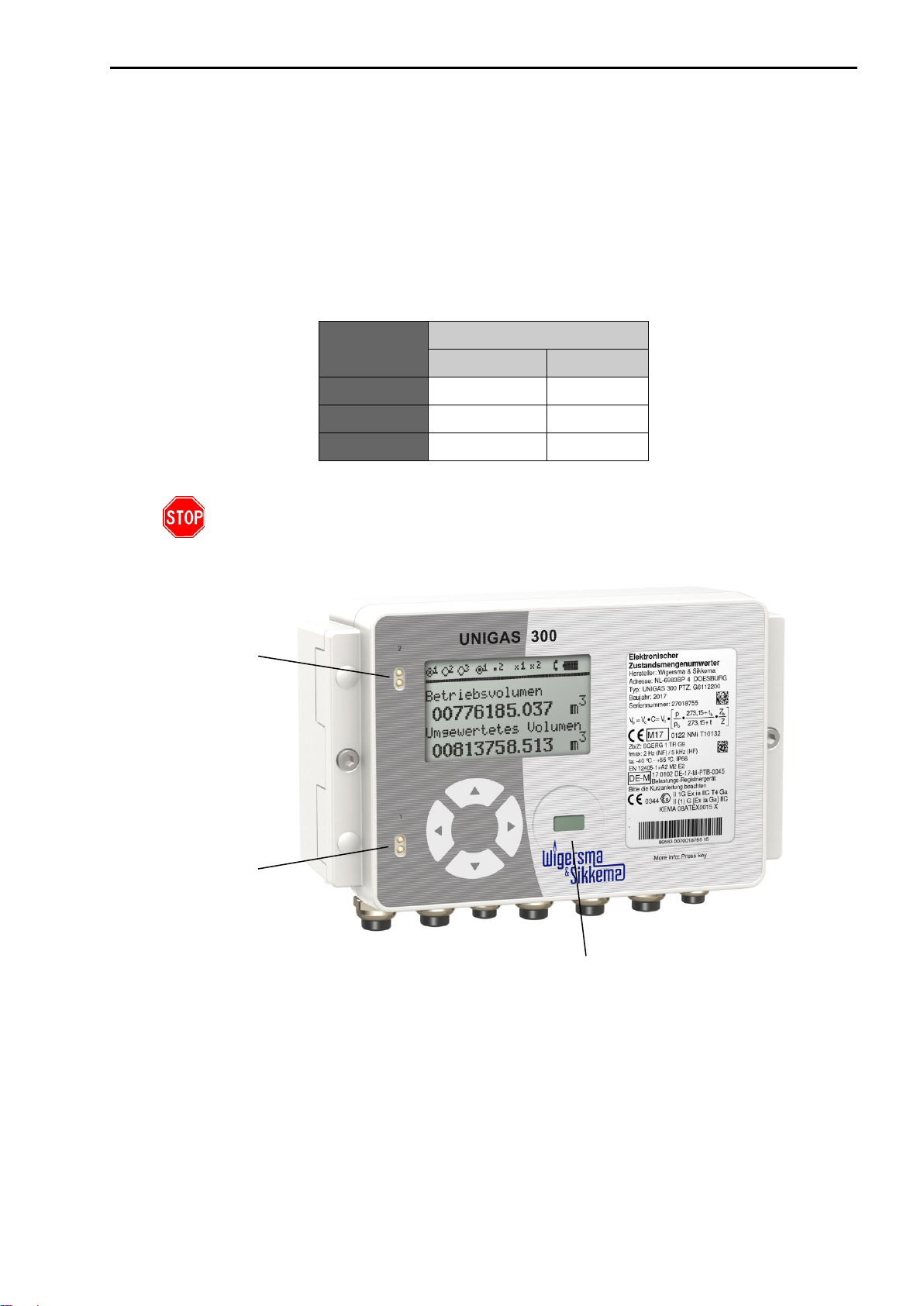
UNIGAS 300 is equipped with two communication ports; depending on the selected protocol, it will be available
on communication port 1 (modem port) or communication port 2 (user port).
Protocol
Communication port
1
2
IDOM
V
-
FTP
V
-
MODBUS
V
V
If the service port of UNIGAS 300 is used during or in a 30 second period prior to the
forwarding of an IDOM or FTP message, it is possible that forwarding the IDOM or
FTP message fails.
Communication port 2
Communication port 1
Service port

Installation and operating manual CI-module UNIGAS 300
DDG6010MHEN/09-2023/Rev.A5 4
The following must be taken into account when using both communication ports:
•When using MODBUS on either port, IEC 62056-21 cannot be communicated on the other port
simultaneously. There should be at least 5 s space between the use of both ports.
•When using MODBUS on both ports, MODBUS cannot be communicated simultaneously. There should
be at least 5 s space between the use of both ports.
If it cannot be guaranteed that simultaneous communication will not occur when using both communication
ports, the use of both ports is not recommended. This may lead to interference or blocking of communication
for both ports.
•If no protocol is configured on the CI module, IEC 62056-21 can be communicated on both ports
simultaneously.
•When using FTP or IDOM, while sending the FTP or IDOM message, on port 2 IEC 62056-21 can be
communicated simultaneously.
2 Installing the CI-module
Mounting instruction DDG6006MHML describes installation of the CI-module in UNIGAS 300.
Installing the CI module in UNIGAS 300 will not affect the programmed settings of the CI module.
Consequently, it is possible to exchange the CI module between several UNIGAS 300 units without any
need to change the settings in the CI module.
CI module located in UNIGAS 300
Only place the CI module in UNIGAS 300 if the pillar (figure above (1)) is present.
When installing a CI module, as indicated at (3) in the installation manual
DDG6006MHML, the ring must not be replaced!
(1)

Installation and operating manual CI-module UNIGAS 300
DDG6010MHEN/09-2023/Rev.A5 5
3 IDOM
The IDOM protocol can be used as follows. UNIGAS 300 is connected to an RTU. The RTU will collect the
data forwarded by the CI module in UNIGAS 300. Subsequently, the RTU will forward the data to a central
system.
At a 5-min interval on the 5-min moment, UNIGAS 300 will forward the data over the users port
(communications port 1). The RTU will receive these data and process into a load profile.
3.1 Data structure
The IDOM protocol will forward the following data.
Sequence
Description
Output/ format
Unit
Remarks
1
Non-converted volume
Va:########[CR]
m3
2
Converted volume
Vr:######## [CR]
m3
3
Pressure
P#.###[CR]
bar
4
Temperature
T±##.##[CR]
Degrees
Celsius
5
Alarm
@[CR]
Only present in case of an
alarm.
Example:
Va:01209188[CR]
Vr:01206764[CR]
P0.999[CR]
T+01.60[CR]
An alarm is set under the conditions specified in Chapter 6 of UNIGAS 300 manual DDG6004MHGB, table:
"Status register 1; calibration relevant alarms" (97:97.1).
3.2 Data format
Baud rate: 4800
Parity: Even
Data bits: 7
Stop bits: 1
3.3 IDOM settings
The settings for IDOM in the CI module are made by means of UNITOOL.
The settings are
•System information; Protocol: Off, FTP, IDOM, MODBUS
•All the other settings are not relevant
Settings marked in bold shall be made to activate the IDOM mode.
Installation and operating manual CI-module UNIGAS 300
DDG6010MHEN/09-2023/Rev.A5 6
4 FTP messages
For sending FTP messages a UNICOM 300 (or UNILOG GPRS/300)shall be connected to the modem port
(communication port 1) of UNIGAS 300. FTP communication will send a file to the designated FTP server.
The CI module will request UNICOM 300 (or UNILOG GPRS/300) to establish a FTP connection. It is
therefore important that UNICOM 300 (or UNILOG GPRS/300) is provided with the correct settings of the
FTP server which messages will be sent towards. The module reads and transfers the load profile P.01 of
UNIGAS 300. The load profile P.01 can be set in UNIGAS 300 (5, 10, 15, 30, 60 min. or 24 hour).
The number of channels in the FTP file corresponds with the number of channels of the UNIGAS 300. More
information on the load profile can be found in the UNIGAS 300 user manual.
Three different file formats of the FTP file are supported:
•XML
•IEC 62056-21
•CSV
When FTP is active, it will have priority communication on any other connections with
UNIGAS 300. When a modem connection is active, UNICOM 300 (or UNILOG GPRS/300)
will terminate the current connection and start a FTP session.
4.1 Start FTP
The FTP session will be activated depending on the programmed FTP interval. The FTP session starts 10
seconds after rogrammed interval. It is also possible to set up a additional delay (FTP offset) to the FTP
session. The moment of starting the FTP is FTP interval + 10 Seconds + FTP offset, example given; FTP
interval 5 minutes and FTP offset 25 seconds. The FTP session will commence on 5 min + 10 seconds + 25
second = xx:05:25. The next FTP message will be sent on xx:10:25, xx:15:25 and so forth.
4.2 First FTP message
The first FTP message the CI module sends, is a maximum of 7 days of data of the programmed interval of
the load profile. In case of a five minuten interval, the FTP message will consist out of a maximum of 7 days *
24 hours * 12 (5 minutes interval) = 2016 entries.
Once every hour (5 minutes before the hour) the date of the last received load profile is saved. This prevents
that when the CI module is reinstated in the same UNIGAS 300, the FTP message will contain 7 days of
loggings. The FTP message will contain only last hours data.
When the CI modules is reinstated in a different UNIGAS 300 , the FTP message will contain
a maximum of 7 days of data.
4.3 FTP file
The ftp filename consists of:
•Manufacturer ID
•Device serial number
•Date and Time
•Fixed text
•File extension depending on format.
E.g.: KAM[27000100][0091014161055]LP.txt
Installation and operating manual CI-module UNIGAS 300
DDG6010MHEN/09-2023/Rev.A5 7
4.4 XML file format
The XML file format has the extension .xml. CR and LF are not applied to show line breaks.
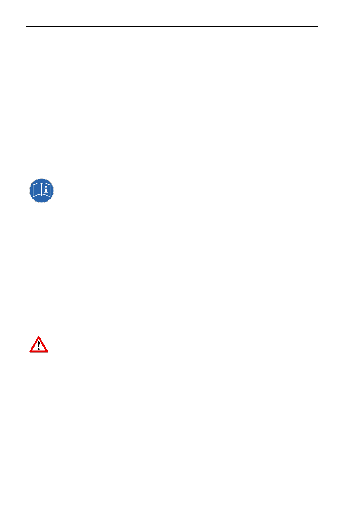
4.4.1 XSD
An XSD is available which defines XML message structure.
Channel 12 of the xml message (ChValue) has the same value as status.
Next examples contain 2 loggings of 5 minute interval.
Example:
<?xml version="1.0" encoding="UTF-8"?><DeviceArchiveFile
xmlns:xsi="http://www.w3.org/2001/XMLSchema-
instance"><SN>27000412</SN><Header><Interval>5</Interval><NrOfChs>12</NrOfChs><OVList><OV
><Obis>7-1:11.2.0</Obis><Unit>m3</Unit></OV><OV><Obis>7-1:12.1.0</Obis>
<Unit>m3</Unit></OV><OV><Obis>7-1:13.0.0</Obis><Unit>m3</Unit></OV><OV><Obis>7-
1:11.1.0</Obis><Unit>m3</Unit></OV><OV><Obis>7-2:13.0.0</Obis><Unit>m3</Unit></OV>
<OV><Obis>7-3:13.0.0</Obis><Unit>m3</Unit></OV><OV><Obis>7-1:41.0.0</Obis>
<Unit>C</Unit></OV><OV><Obis>7-1:42.0.0</Obis><Unit>mbar</Unit></OV><OV>
<Obis>97:97.1</Obis><Unit></Unit></OV><OV><Obis>97:97.2</Obis><Unit></Unit></OV><OV><Obi
s>97:97.3</Obis><Unit></Unit></OV><OV><Obis>97:97.4</Obis><Unit></Unit></OV></OVList></He
ader><Rows><Row><Time>2010-03-22 00:45:00</Time>
<Status>0000</Status><Chs><Ch><ChValue>20631215</ChValue></Ch><Ch><ChValue>00006138</Ch
Value></Ch><Ch><ChValue>21992096</ChValue></Ch><Ch><ChValue>21992096</ChValue></Ch><C
h><ChValue>00000002</ChValue></Ch><Ch><ChValue>00000002</ChValue></Ch><Ch><ChValue>00
001764</ChValue></Ch><Ch><ChValue>00102190</ChValue></Ch><Ch><ChValue>0010</ChValue><
/Ch><Ch><ChValue>0000</ChValue></Ch><Ch><ChValue>00FF</ChValue></Ch><Ch><ChValue>000
0</ChValue></Ch></Chs></Row><Row><Time>2010-03-22
00:50:00</Time><Status>0000</Status><Chs><Ch><ChValue>20631499</ChValue>
</Ch><Ch><ChValue>00006138</ChValue></Ch><Ch><ChValue>21992396</ChValue></Ch><Ch><Ch
Value>21992396</ChValue></Ch><Ch><ChValue>00000002</ChValue></Ch><Ch><ChValue>0000000
2</ChValue></Ch><Ch><ChValue>00001763</ChValue></Ch><Ch><ChValue>00102187</ChValue></
Ch><Ch><ChValue>0010</ChValue></Ch><Ch><ChValue>0000</ChValue></Ch><Ch><ChValue>00F
F</ChValue></Ch><Ch><ChValue>0000</ChValue></Ch></Chs></Row></Rows></DeviceArchiveFile>
Installation and operating manual CI-module UNIGAS 300
DDG6010MHEN/09-2023/Rev.A5 8
4.5 IEC 62056-21 file format
The FTP file has the extension .txt. The IEC 62056-21 file consists out of one or more data blocks with a max
of 99 entries (loggings) bestaat uit één of meerdere datablokken met maximaal 99 entries (loggings) each.
Each data block is provided of a data header, a BCC and characters [STX] and [EOT]. The file is terminated
with marking of the character [ETX].
Example given:
[STX]P.52(0100215150000)(0000)(5)(11)(7-1:11.2.0)(m3)(7-1:12.1.0)(m3)(7-1:13.0.0)(m3)(7-1:11.1.0)(m3)(7-
2:13.0.0)(m3)(7-3:13.0.0)(m3)(7-1:41.0.0)(C)(7-1:42.0.0)(mbar)(97:97.1)()(97:97.2)()(97:97.3)()[CR][LF]
(17772111)(00006138)(19019721)(19019721)(00000002)(00000002)(-00000176)(00100555)(0010)
(0000)(00FF)[CR][LF]
(17772410)(00006138)(19020021)(19020021)(00000002)(00000002)(-00000141)(00100551)(0010)
(0000)(0033)[CR][LF]
[ETX][ENQ]
4.6 CSV file format
The FTP file has the extension .csv. The CSV file has one more channel than the load profile of UNIGAS 300.
The last channel is the VDEW status bit .
Example given:
0.9.2,0.9.1,7-1:11.2.0(m3),7-1:12.1.0(m3),7-1:13.0.0(m3),7-1:11.1.0(m3),7-2:13.0.0(m3),7-3:13.0.0(m3),7-1:41.0.0(C),7-
1:42.0.0(mbar),97:97.1(),97:97.2(),97:97.3(),97:97.4()[CR][LF]
2010-02-15,15:20,17773309,00006138,19020921,19020921,00000002,00000002,-00000162,00100540,0010,0000
,00FF ,0000[CR][LF]
2010-02-15,15:25,17773608,00006138,19021221,19021221,00000002,00000002,-00000136,00100547,0010,0000
,00FF,0000[CR][LF]
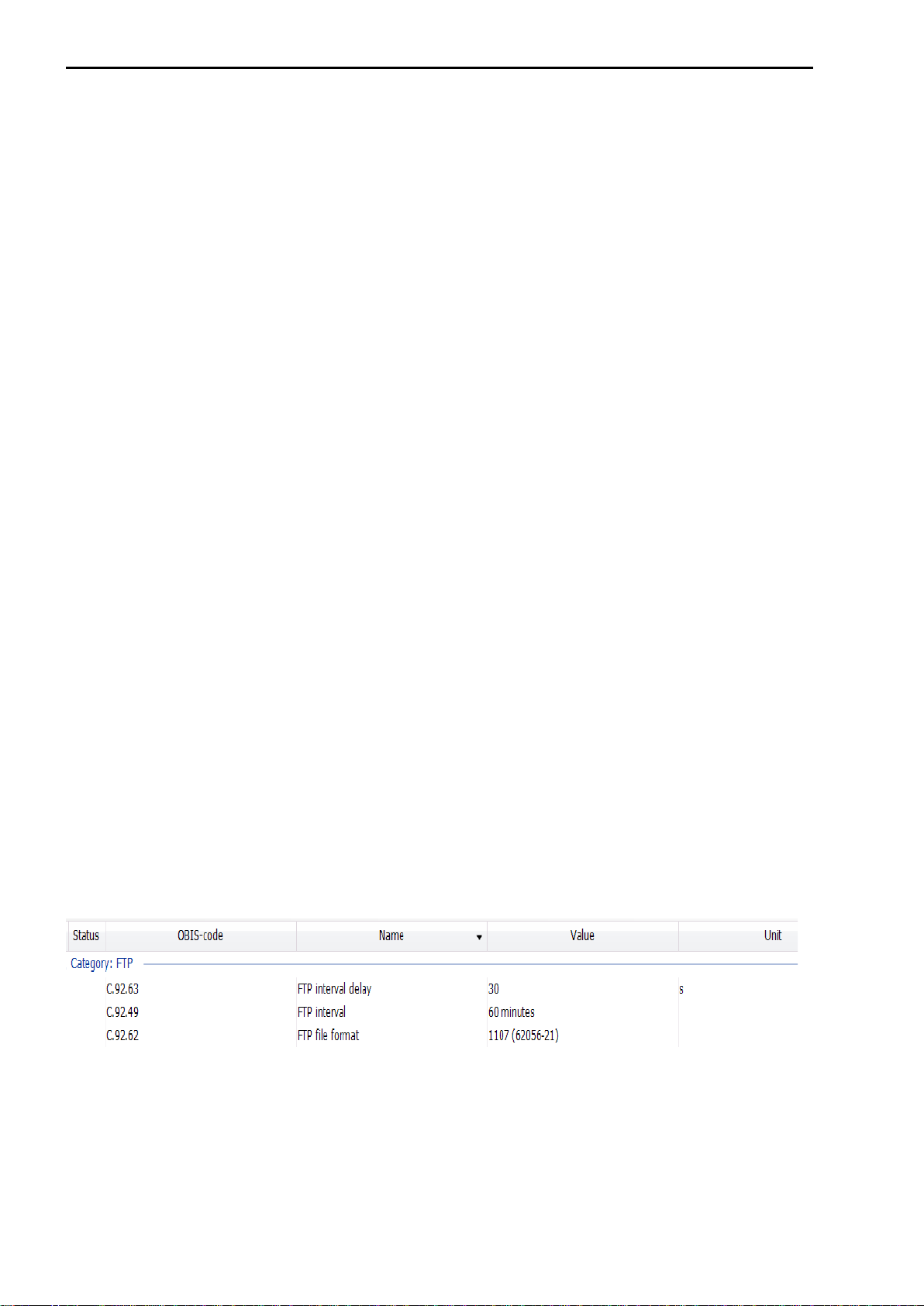
4.7 FTP settings
FTP settings of the CI module can be programmed with UNITOOL. Connect with UNITOOL to MODULE1B,
device address MODULE1B.
Open the menu GPRS for all settings regarding FTP.
Programmable settings are:
•Menu GPRS; FTP interval; off, 5 minutes, 10 minutes, 15 minutes, 30 minutes, 60 minutes, 1day
•Menu GPRS; FTP file format; IEC 62056-21,CSV, XML
•Menu GPRS; FTP interval offset; 0till 999 seconds.
•Menu System information; Protocol: Off, FTP, IDOM, MODBUS
Bold marked settings must be set for FTP communication.

Installation and operating manual CI-module UNIGAS 300
DDG6010MHEN/09-2023/Rev.A5 9
5 Modbus
5.1 Introduction:
Modbus protocol can be read out easily by use of RS485 or RS232. Communication takes place through
communication port 1 or communication port 2 of the UNIGAS 300.
Each Modbus message has the same structure, supporting the modes ASCII and RTU. The advantage of
RTU is that fewer characters are sent.
Modbus supports mode RTU and ASCII with 300, 600, 1200, 2400, 4800 and 9600 baudrate.
Table: Modbus ASCII or RTU
Modbus/ASCII
Modbus/RTU
Characters
ASCII 0...9en A..F
Binary 0...255
Checksum
LRC Longitudinal Redundancy
Check
CRC Cyclic Redundancy
Check
Frame start
character ':'
3,5 characters’ silence
Frame end
characters CR/LF
3,5 characters’ silence
Holes in
message
1 sec
1,5 times character length
Start bit
1
1
Data bits
7
8
Parity
even
none
Stop bits
1
1
When the Modbus protocol is active on communication port 1, it is not possible to read out the CI module of
the UNIGAS 300 by means of IEC 62056-21. For reading out with IEC 62056-21, a command must first be
issued to temporarily deactivate Modbus.
The registers of Modbus are not configurable. The adressing of the Modbus register is defined in the
mapping table (see 5.2 Modbus Registers). The mapping table also defines the Modbus format, the link with
the correct OBIS parameter and the size of the OBIS parameter. The multipliers for read out of OBIS
parameter Modbus are also defined in this table.
Example given:
Register address 1: OBIS parameter C.6.1 with OBIS multiplier 10.
When reading out the parameter from UNIGAS 300 the read out divided by the multiplier. Actual value 631 is
the same as 63.1Ah. However, Modbus multiplies this value times 10

Installation and operating manual CI-module UNIGAS 300
DDG6010MHEN/09-2023/Rev.A5 10
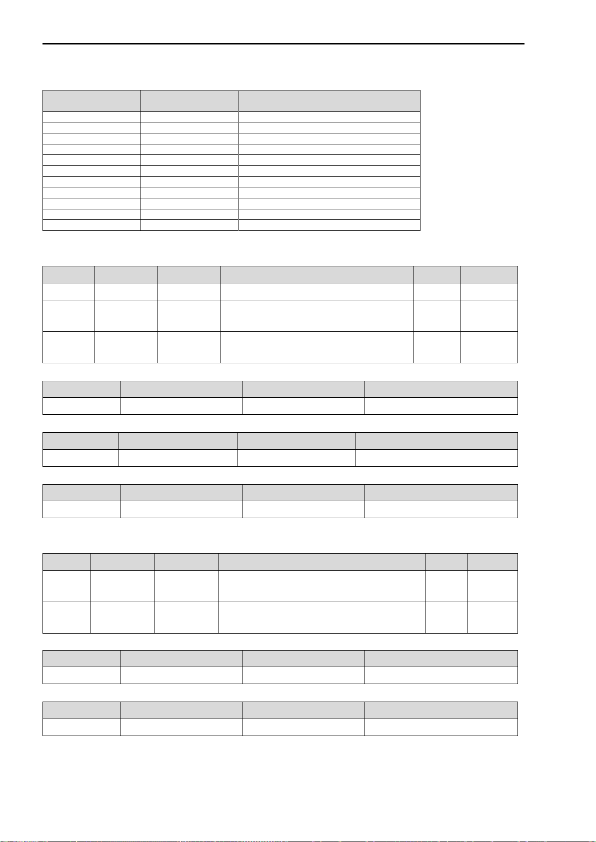
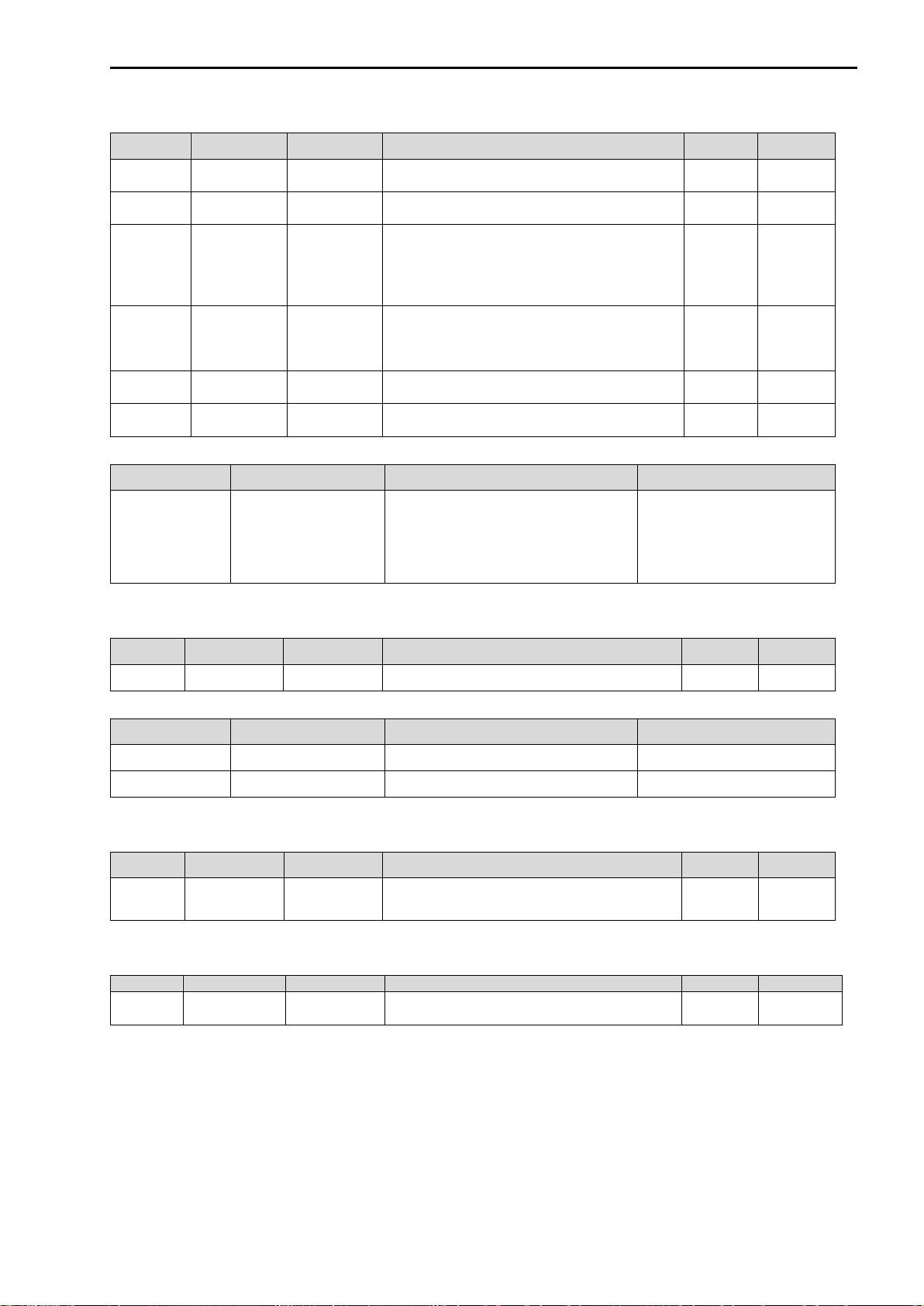
5.2 Modbus Registers
Register
Modbus
format
Sca-
ling
Ab.
Description
OBIS code
Unit
1
USHORT
10
Ah_used
Battery capacity
C.6.1
10-1 Ah
2
HEX2
1
Register 1
calibration relevant alarms
97:97.1
-
3
USHORT
1
Vm1
unconverted volume, total volume at
measuring conditions, input 1
Post decimal places
7-1:13.0.0
10-3 m3
4
USHORT
1
Vb1
converted volume, undisturbed
volume at base conditions, input 1
Post decimal places
7-1:11.2.0
10-3 m3
5*
HEX2
1
Register 2
Operational_status
97:97.2
-
6*
HEX2
1
Register 3
Alarm_reports
97:97.3
-
7*
HEX2
1
Register 4
VDEW status
97:97.4
-
101
ULONG
1
Vm1
unconverted volume, total volume at
measuring conditions, input 1
Pre decimal places
7-1:13.0.0
m3
103
ULONG
1
Vb1
converted volume, undisturbed
volume at base conditions, input 1
Pre decimal places
7-1:11.2.0
m3
301
IEEEFLOAT
1
pb
Reference pressure (base
conditions)
7-1:42.2.0
mbar
303
IEEEFLOAT
1
tb
Reference temperature (base
conditions)
7-1:41.2.0
°C
305
IEEEFLOAT
1
p
Pressure
7-1:42.0.0
mbar
307
IEEEFLOAT
1
p
Pressure
7-1:42.0.0
mbar
309
IEEEFLOAT
1
t
Temperature
7-1:41.0.0
°C
311
IEEEFLOAT
1
C
Calculated conversion factor
7-1:52.2.0
-
313
IEEEFLOAT
1
Z/Zbfix
Fixed value used for conversion
7-1:53.3.0
-
315
IEEEFLOAT
1
pfix
Fixed value for the pressure used for
conversion
7-1:42.3.0
mbar
317
IEEEFLOAT
1
tfix
Fixed value for the temperature used
for conversion
7-1:41.3.0
°C
319
IEEEFLOAT
1
N2
Nitrogen concentration N2
C.96.3
mol %
321
IEEEFLOAT
1
H2
Hydrogen concentration H2
C.96.2
mol %
323
IEEEFLOAT
1
CO2
Carbon dioxide concentration CO2
C.96.1
mol %
327
IEEEFLOAT
1
Qc1_5
Flow at measuring conditions based
upon 5 minutes interval, total value
7-1:43.1.1
m3/h
329
IEEEFLOAT
1
Qb1_5
Flow at base conditions, undisturbed
value based upon 5 minutes interval
7-1:43.2.1
m3/h
333
IEEEFLOAT
1
Hs
Calorific value of 1 m3 gas at 25 °C
7-1:54.11.0
MJ/m3
335
IEEEFLOAT
1
d
Relative density compared to air at 0
°C
7-1:45.11.0
-
337
IEEEFLOAT
1
pb
Reference pressure (base
conditions)
7-1:42.2.0
mbar
339
IEEEFLOAT
1
tb
Reference temperature (base
conditions)
7-1:41.2.0
°C
341*
IEEEFLOAT
1
Qc1_nx5
flow rate corrected operating volume
on the basis of
moving average of n x 5 min
7-1:43.1.2
m3/h
343*
IEEEFLOAT
1
Qc1_inst
flow rate corrected operating volume
on the basis of
increase ΔVc/t
7-1:43.1.0
m3/h
345*
IEEEFLOAT
1
Vc1_60
corrected operating volume (current
clock hour
consumption)
7-1:43.1.71
m3
347*
IEEEFLOAT
1
Qb1_nx5
flow rate converted volume on the
basis of moving
average of n x 5 min,
7-1:43.2.2
m3/h
349*
IEEEFLOAT
1
Qb1_inst
flow rate converted volume on the
basis of Qc1_inst x
C-factor
7-1:43.2.0
m3/h
351*
IEEEFLOAT
1
Vb1_60
converted volume (current hour)
7-1:43.2.71
m3

Installation and operating manual CI-module UNIGAS 300
DDG6010MHEN/09-2023/Rev.A5 11
Register
Modbus
format
Scali
ng
Ab.
Description
OBIS code
501
COUNTER
1
Vm1
unconverted volume, total volume at
measuring conditions, input 1
7-1:13.0.0
m3
504
COUNTER
1
Vb1
converted volume, undisturbed
volume at base conditions, input 1
7-1:11.2.0
m3
507*
COUNTER
1
Vc1_err
unconverted volume, disturbed
volume at measuring conditions,
under circumstances of a calibration
error condition and corrected for the
gas meter measuring error
p, t, Z, Zb or CRC error, input 1
7-1:12.0.0
m3
510*
COUNTER
1
Vb1_err
converted volume, disturbed volume
at base conditions, under
circumstances of a calibration error
condition, input 1
p, t, Z, Zb or CRC error
7-1:12.1.0
m3
513*
COUNTER
1
Vm2
unconverted volume, total volume at
measuring conditions, input 2
7-2:13.0.0
m3
516*
COUNTER
1
Vm3
unconverted volume, total volume at
measuring conditions, input 3
7-3:13.0.0
m3
801
BCDNO4
1
Vm1
unconverted volume, total volume at
measuring conditions, input 1
7-1:13.0.0
10-4 m3
805
BCDNO4
1
Vb1
converted volume, undisturbed
volume at base conditions, input 1
7-1:11.2.0
10-4 m3
809*
BCDNO4
1
Vc1_err
unconverted volume, disturbed
volume at measuring conditions,
under circumstances of a calibration
error condition and corrected for the
gas meter measuring error
p, t, Z, Zb or CRC error, input 1
7-1:12.0.0
m3
813
BCDTIME2
1
Time
Current time (Read/Write)
0.9.1
-
815
BCDDATE
1
Date
Current date (Read/Write)
0.9.2
-
817
BCDNO3
1
Serial number
Serial number UNIGAS 300
C.1.0
-
820
BCDNO
100
Gas day
Moment at which UNIGAS 300
closes and logs the day, as in day
logger (end of gas day)
C.91.2
-
822*
BCDNO4
1
Vb1_err
converted volume, disturbed volume
at base conditions, under
circumstances of a calibration error
condition, input 1
p, t, Z, Zb or CRC error
7-1:12.1.0
m3
826
BCDNO4
1
Vm2
unconverted volume, total volume at
measuring conditions, input 2
7-2:13.0.0
m3
830
BCDNO4
1
Vm3
unconverted volume, total volume at
measuring conditions, input 3
7-3:13.0.0
m3
60000
USHORT
1
Disable Modbus (**)
Deactivate modbus for IEC 62056-
21 communication. Modbus is
enabled if no communication during
40 seconds (protocol time-out)
N.A.
-
(*) Register added in firmware version 2.0.24 .
(**) This address is used to temporarily disable Modbus. This way, direct communication over IEC 62056-21
is possible with UNIGAS 300. Modbus will become active again after a protocol time-out of 40 seconds.
Installation and operating manual CI-module UNIGAS 300
DDG6010MHEN/09-2023/Rev.A5 12
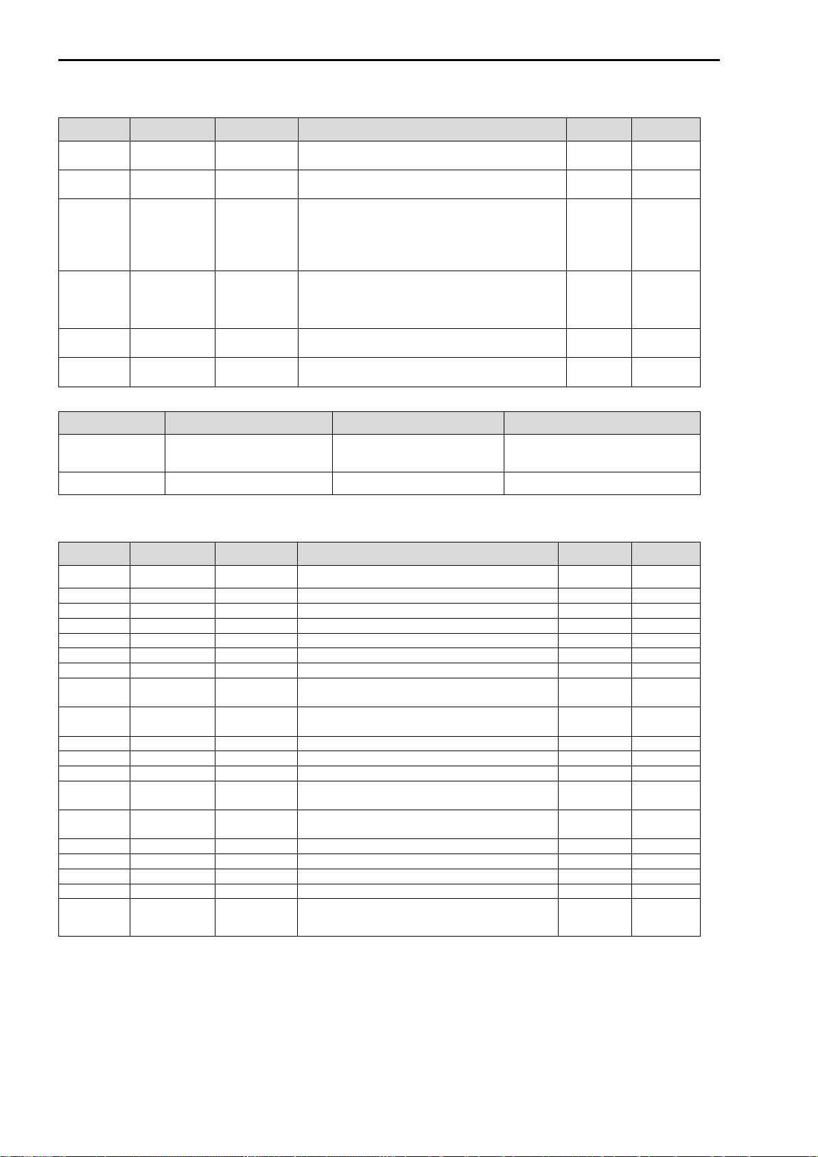
5.3 Data types
Type
Size in 16bit
registers
Format
USHORT
1*16bit
Binary digit
ULONG
2*16bit
Binary digit
COUNTER
2*16bit + 1*16bit
Binary counter
BCDTIME
1*16bit
BCD
BCDTIME2
2*16bit
BCD
BCDDATE
2*16bit
BCD
BCDNO
1*16bit
BCD
BCDNO3
3*16bit
BCD
BCDNO4
4*16bit
BCD
IEEEFLOAT
2*16bit
Binary. Single precision floating point
HEX2
1*16bit
Hex formatted code
5.3.1 Ushort
Register
OBIS code
Ab.
Description
Unit
Scaling
1
C.6.1
Ah_used
Battery capacity
Ah
10-1
3
7-1:13.0.0
Vm1
unconverted volume, total volume at
measuring conditions, input 1
Post decimal places
m3
10-3
4
7-1:11.2.0
Vb1
converted volume, undisturbed volume at
base conditions, input 1
Post decimal places
10-3 m3
10-3
Function Code
Modbus Command
Answer
Meaning
03
3F 03 00 01 00 01 BC
3F 03 02 00 04 B8
0,4 Ah
Function Code
Modbus Command
Answer
Meaning
03
3F 03 00 03 00 01 BA
3F 03 02 00 E7 D5
xxx.231 m3(post dec. Places)
Function Code
Modbus Command
Answer
Meaning
03
3F 03 00 04 00 01 B9
3F 03 02 00 49 73
xxx.730 m3(post dec. Places)
5.3.2 ULONG
Register
OBIS code
Ab.
Description
Unit
Scaling
101
7-1:13.0.0
Vm1
unconverted volume, total volume at measuring
conditions, input 1
Pre decimal places
m3
-
103
7-1:11.2.0
Vb1
converted volume, undisturbed volume at base
conditions, input 1
Pre decimal places
m3
-
Function Code
Modbus Command
Answer
Meaning
03
3F 03 00 65 00 02 57
3F 03 04 01 8E C8 B5 AE
26134709 m3
Function Code
Modbus Command
Answer
Meaning
03
3F 03 00 67 00 02 55
3F 03 04 01 8E 9D 8E 00
26123662 m3
Installation and operating manual CI-module UNIGAS 300
DDG6010MHEN/09-2023/Rev.A5 13
5.3.3 Counter
Register
OBIS code
Ab.
Description
Unit
Scaling
501
7-1:13.0.0
Vm1
unconverted volume, total volume at
measuring conditions, input 1
m3
-
504
7-1:11.2.0
Vb1
converted volume, undisturbed volume at
base conditions, input 1
m3
-
507
7-1:12.0.0
Vc1_err
unconverted volume, disturbed volume at
measuring conditions, under circumstances of
a calibration error condition and corrected for
the gas meter measuring error
p, t, Z, Zb or CRC error, input 1
m3
-
510
7-1:12.1.0
Vb1_err
converted volume, disturbed volume at base
conditions, under circumstances of a
calibration error condition, input 1
p, t, Z, Zb or CRC error
m3
-
513
7-2:13.0.0
Vm2
unconverted volume, total volume at
measuring conditions, input 2
m3
-
516
7-3:13.0.0
Vm3
unconverted volume, total volume at
measuring conditions, input 3
m3
-
Function Code
Modbus Command
Answer
Meaning
03
3F 03 01 F5 00 03 C5
3F 03 06 01 8E EE 24 00 E7 30
➔01 8E EE 24 =
26144292 m3
➔00 E7 = ,231 m3
➔26144292,231 m3
5.3.4 BCDDate
Register
OBIS code
Ab.
Description
Unit
Scaling
815
0.9.2
Date
Current date
-
-
Function Code
Modbus Command
Answer
Meaning
03
3F 03 03 2F 00 02 8A
3F 03 04 20 14 02 13 71
13 februari 2014
71
5.3.5 BCDNO
Register
OBIS code
Ab.
Description
Unit
Scaling
820
C.91.2
Gas day
Moment at which UNIGAS 300 closes and
logs the day, as in day logger (end of gas day)
-
-
5.3.6 BCDNO3
Register
OBIS code
Ab.
Description
Unit
Scaling
817
C.1.0
Serial
number
Serial number UNIGAS 300
-
-
Installation and operating manual CI-module UNIGAS 300
DDG6010MHEN/09-2023/Rev.A5 14
5.3.7 BCDNO4
Register
OBIS code
Ab.
Description
Unit
Scaling
801
7-1:13.0.0
Vm1
unconverted volume, total volume at
measuring conditions, input 1
10-4 m3
-
805
7-1:11.2.0
Vb1
converted volume, undisturbed volume at
base conditions, input 1
10-4 m3
-
809
7-1:12.0.0
Vc1_err
unconverted volume, disturbed volume at
measuring conditions, under circumstances of
a calibration error condition and corrected for
the gas meter measuring error
p, t, Z, Zb or CRC error, input 1
10-4 m3
822
7-1:12.1.0
Vb1_err
converted volume, disturbed volume at base
conditions, under circumstances of a
calibration error condition, input 1
p, t, Z, Zb or CRC error
10-4 m3
826
7-2:13.0.0
Vm2
unconverted volume, total volume at
measuring conditions, input 2
10-4 m3
830
7-3:13.0.0
Vm3
unconverted volume, total volume at
measuring conditions, input 2
10-4 m3
Function Code
Modbus Command
Answer
Meaning
03
3F 03 03 21 00 04 96
3F 03 08 00 00 26 14 53 27
23 10 CF
000026145327,2310 m3
53 27 23 10 CF
5.3.8 IEEEFLOAT
Register
OBIS code
Ab.
Description
Unit
Scaling
301
7-1:42.2.0
pb
Reference pressure (base conditions)
mbar
-
303
7-1:41.2.0
tb
Reference temperature (base conditions)
°C
-
305
7-1:42.0.0
p
Pressure
mbar
-
307
7-1:42.0.0
p
Pressure
mbar
-
309
7-1:41.0.0
t
Temperature
°C
-
311
7-1:52.2.0
C
Calculated conversion factor
-
-
313
7-1:53.3.0
Z/Zbfix
Fixed value used for conversion
-
-
315
7-1:42.3.0
pfix
Fixed value for the pressure used for
conversion
mbar
-
317
7-1:41.3.0
tfix
Fixed value for the temperature used for
conversion
°C
-
319
C.96.3
N2
Nitrogen concentration N2
mol %
-
321
C.96.2
H2
Hydrogen concentration H2
mol %
-
323
C.96.1
CO2
Carbon dioxide concentration CO2
mol %
-
327
7-1:43.1.1
Qc1_5
Flow at measuring conditions based upon 5
minutes interval, total value
m3/h
-
329
7-1:43.2.1
Qb1_5
Flow at base conditions, undisturbed value
based upon 5 minutes interval
m3/h
-
333
7-1:54.11.0
Hs
Calorific value of 1 m3gas at 25 °C
MJ/m3
-
335
7-1:45.11.0
d
Relative density compared to air at 0 °C
-
-
337
7-1:42.2.0
pb
Reference pressure (base conditions)
mbar
-
339
7-1:41.2.0
tb
Reference temperature (base conditions)
°C
-
341
7-1:43.1.2
Qc1_nx5
flow rate corrected operating volume on the
basis of moving average of n x 5 min
m3/h
-

Installation and operating manual CI-module UNIGAS 300
DDG6010MHEN/09-2023/Rev.A5 15
Register
OBIS code
Ab.
Description
Unit
Scaling
343
7-1:43.1.0
Qc1_inst
flow rate corrected operating volume on the
basis of increase ΔVc/t
m3/h
-
345
7-1:43.1.71
Vc1_60
corrected operating volume (current clock
hour consumption)
m3
-
347
7-1:43.2.2
Qb1_nx5
flow rate converted volume on the basis of
moving average of n x 5 min,
m3/h
-
349
7-1:43.2.0
Qb1_inst
flow rate converted volume on the basis of
Qc1_inst x C-factor
m3/h
-
351
7-1:43.2.71
Vb1_60
converted volume (current hour)
m3
-
Function Code
Modbus Command
Answer
Meaning
03
3F 03 01 2D 00 02 8E
3F 03 04 44 7D 50 00 A9
1013,2500 mbar
5.3.9 HEX2
Register
OBIS code
Ab.
Description
Unit
Scaling
2
97:97.1
Register 1
calibration relevant alarms
-
-
5
97:97.2
Register 2
Operational status
-
-
6
97:97.3
Register 3
Alarm reports
-
-
7
97:97.4
Register 4
VDEW status
-
-
Function Code
Modbus Command
Answer
Meaning
03
3F 03 00 02 00 01 BB
3F 03 02 00 0A B2
000A
Installation and operating manual CI-module UNIGAS 300
DDG6010MHEN/09-2023/Rev.A5 16
5.4 Read out examples
5.4.1 Register 1 -7
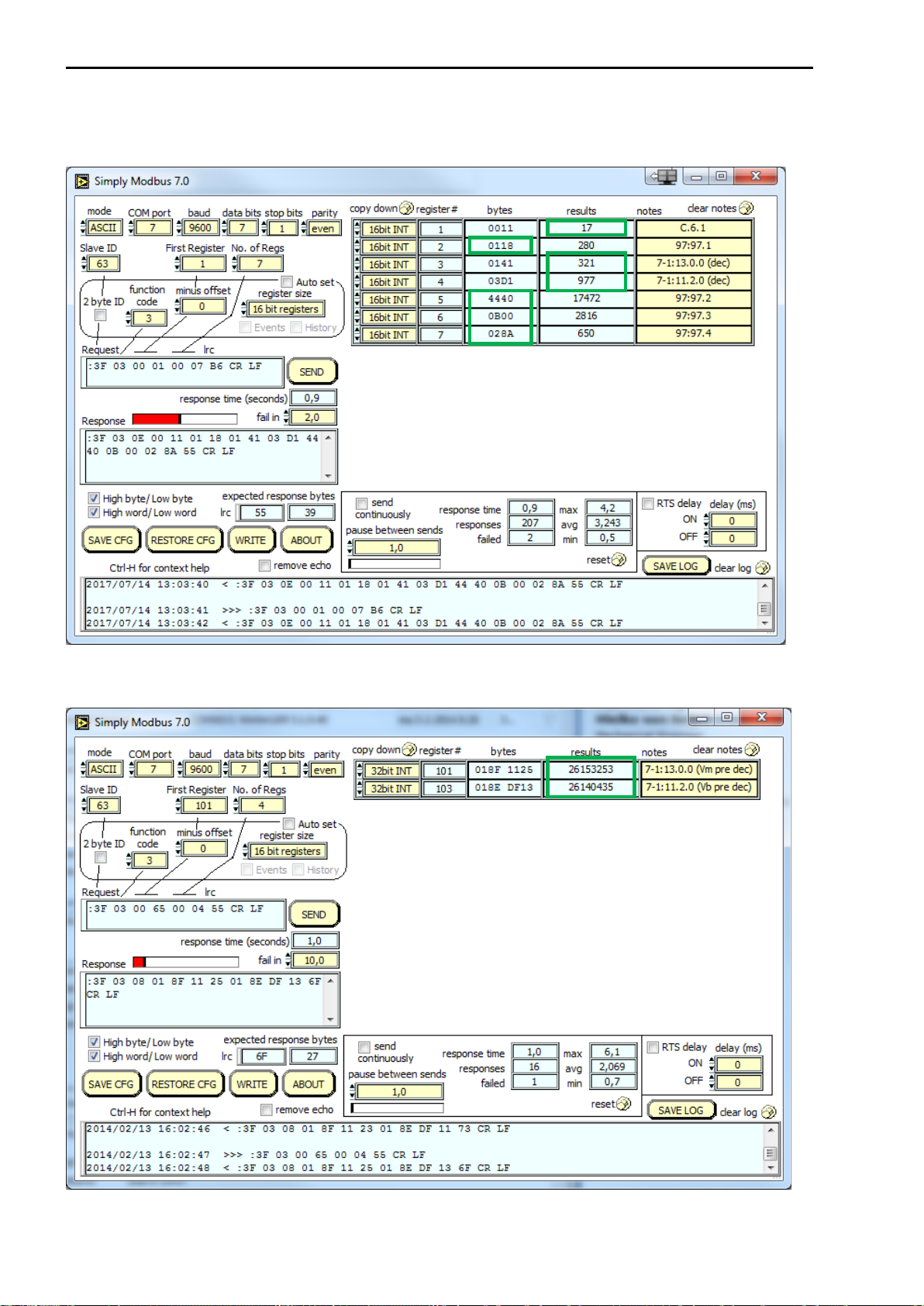
5.4.2 Register 101 -104
Installation and operating manual CI-module UNIGAS 300
DDG6010MHEN/09-2023/Rev.A5 17
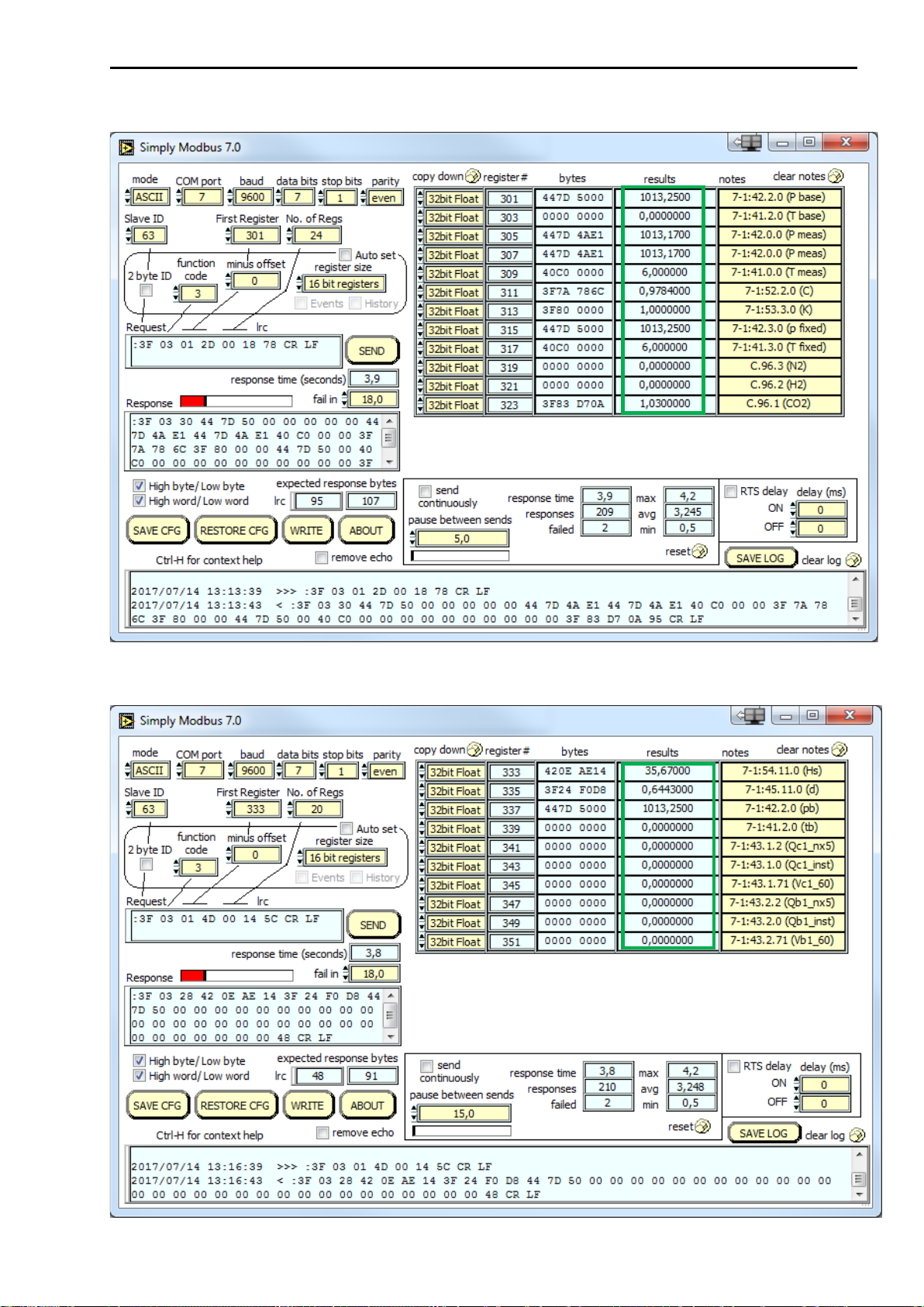
5.4.3 Register 301 –324
5.4.4 Register 327 –351

Installation and operating manual CI-module UNIGAS 300
DDG6010MHEN/09-2023/Rev.A5 18
5.4.5 Register 501 –506
5.4.6 Register 801 -812
Installation and operating manual CI-module UNIGAS 300
DDG6010MHEN/09-2023/Rev.A5 19
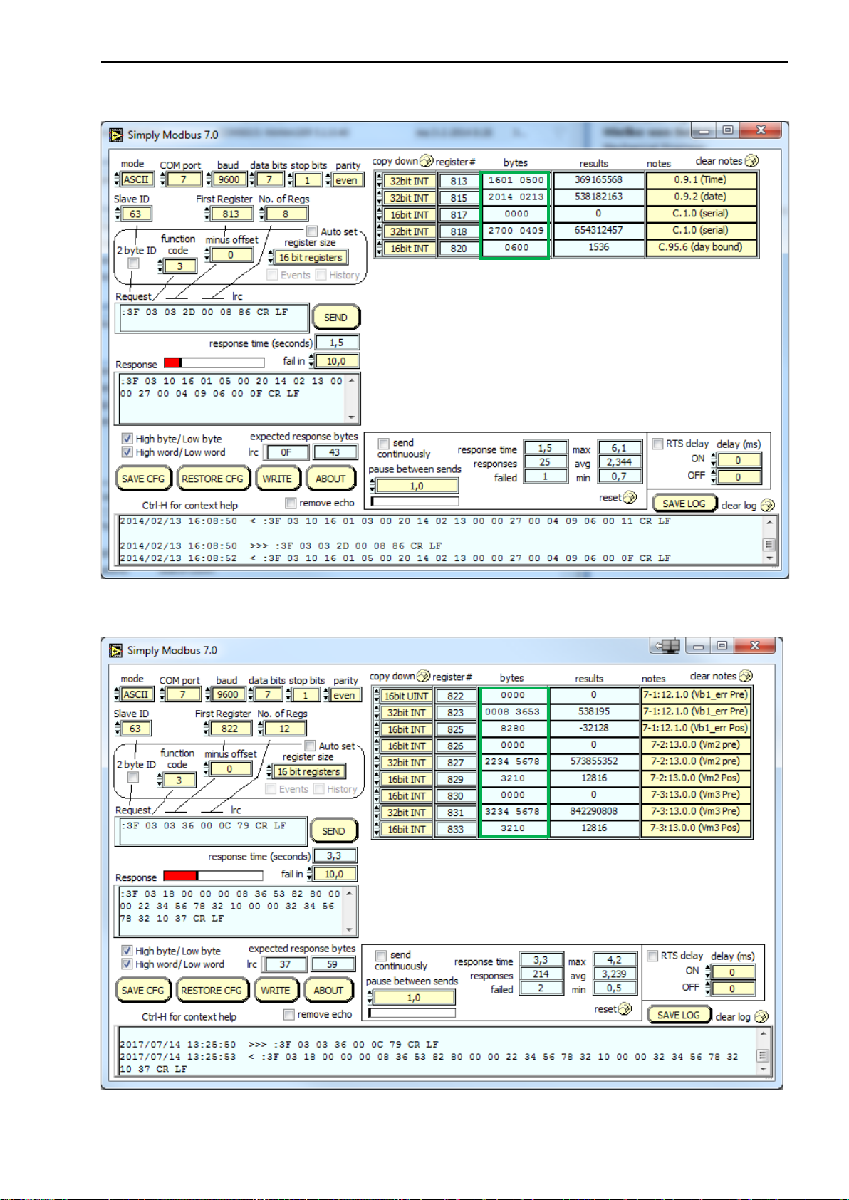
5.4.7 Register 813 –820
5.4.8 Register 822 –833
Other manuals for UNIGAS 300
1
Table of contents
Other Wigersma & Sikkema Control Unit manuals


