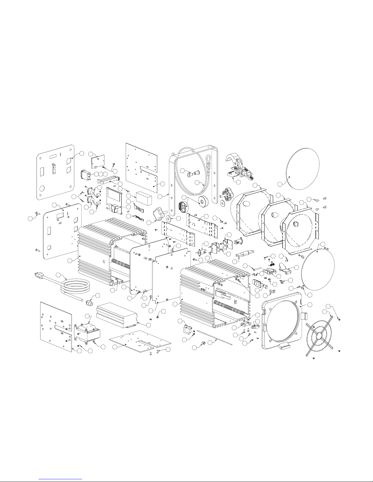
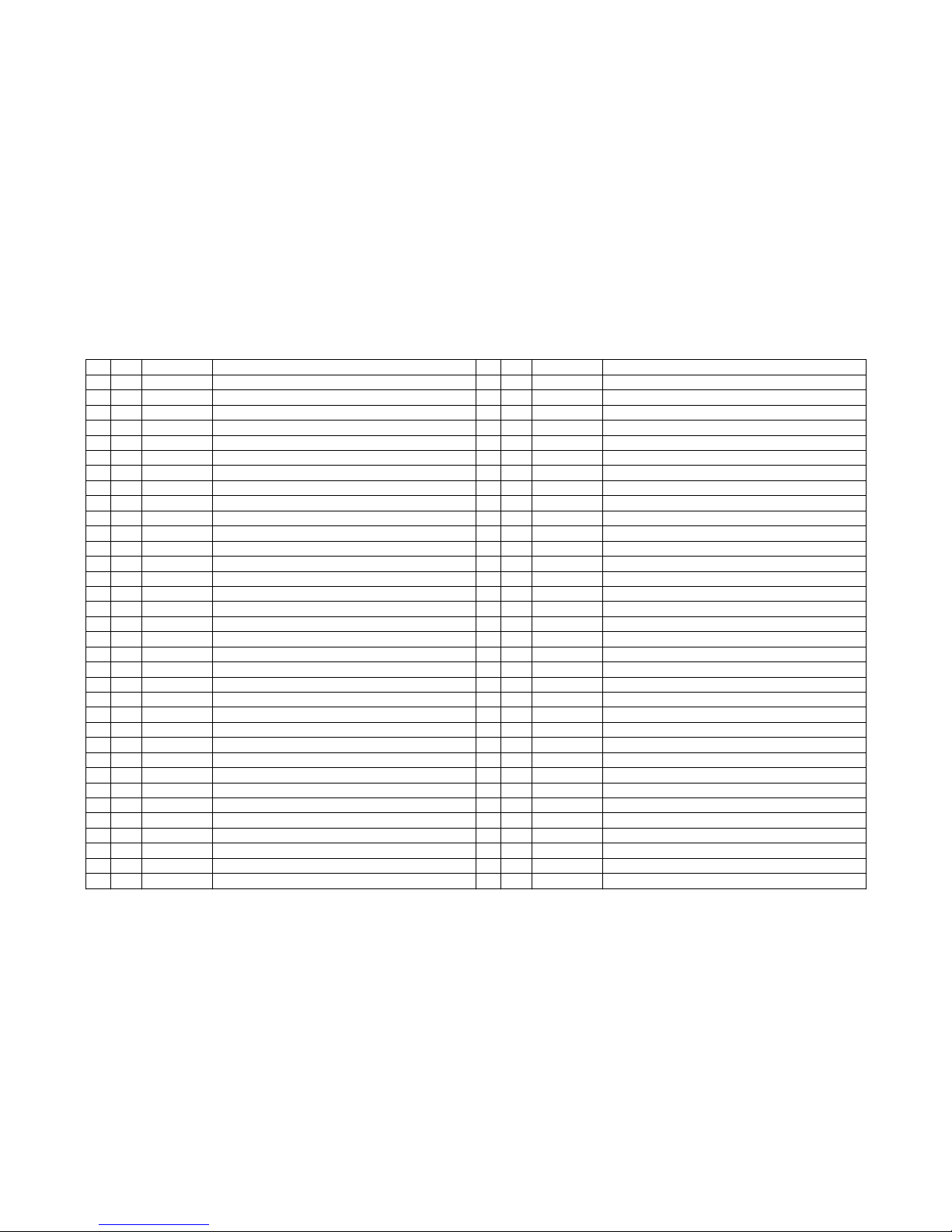
Wildfire Long-Throw LT-400(F)(WS)(S)12 User manual

LT-400(F)(WS)(S)12
LT-400(F)(WS)(S)22
LT-400(F)(WS)(S)32

Table of Contents
Introduction 3
Safety Statements 3
Specifications 4
Setup & Operation 5
Unpacking 5
Optional Accessories 5
Installation 5
Operation 5
DMX Address Mode 6
Lamp Timer Mode 6
DMX Data Mode 6
Dark Mode 6
Changing Reflectors 6
Maintenance & Troubleshooting 7
Lamp Replacement 7
Cleaning 7
Troubleshooting 7
Diagrams 8
Isometric & Line Views 8
Exploded View 9
Part List 10
Schematic 11
Spectral Transmission Graph 12
Photometrics Chart 12
Limited Warranty 13
2

Introduction
Congratulations on your purchase of a Wildfire Long-Throw 400 Series II UV-A Lighting Fixture. This advanced
ultraviolet projector is the flagship of the Long-Throw Series line. Its powerful throw, quiet operation and smooth
even light distribution, has made the Wildfire 400 Series the world’s best selling UV lighting fixture. Features
include advanced interchangeable reflectors, smart electronic ballasting and state-of-the-art digital DMX control
with four user selectable modes for easy integration with intelligent lighting systems. Please take a moment to
read this manual thoroughly before attempting to operate this fixture. Improper set-up, use or servicing may
cause damage to the fixture and/or lamp and void the unit’s warranty.
Safety Statements
CAUTION – RISK OF EXPOSURE TO ULTRAVIOLET (UV) RADIATION. DO NOT OPERATE WITHOUT
COMPLETE LAMP ENCLOSURE IN PLACE, OR IF FILTER GLASS LENS IS DAMAGED
DANGER – INTENSE HEAT. AVOID CONTACT BY PERSONS AND MATERIAL.
CAUTION – RISK OF ELECTRICAL SHOCK AND FIRE. DISCONNECT FIXTURE BEFORE RELAMPING.
USE WITH MAX 400W LAMP TYPE M59 (WILDFIRE IRONARC MODEL LMP-400D). DRY LOCATIONS
ONLY. NOT FOR RESIDENTIAL USE.
WARNING – THIS FIXTURE CONTAINS A HIGH INTENSITY UV METAL HALIDE LAMP, WHICH IS SAFELY
CONTAINED WITHIN AN INTERLOCKING HOUSING. WHEN THIS FIXTURE IS USED IN ACCORDANCE
WITH THE MANUFACTURERS OPERATING INSTRUCTIONS, NO HAZARDS EXIST TO MOST PEOPLE
STANDING WITHIN THE BEAM OF THE FIXTURE. HOWEVER. INDIVIDUALS SUFFERING FROM A RANGE
OF SUNLIGHT EXPOSURE DISORDERS, APHAKIC AND PSEUDOAPHIKIC, OR THOSE INDIVIDUALS
RECEIVING PHOTOSENSITIVE MEDICATION MAY RECEIVE DISCOMFORT IF EXPOSED TO
ULTRAVIOLET LIGHT.
HG – THE LAMP IN THIS FIXTURE CONTAINS MERCURY. MANAGE IN ACCORDANCE WITH DISPOSAL
LAWS. SEE: WWW.LAMPRECYCLE.ORG OR CALL 1-800-937-8065
3

Specifications
Ballast:
Electronic Power Factor >97%
Rating:100 or 120 VAC / 60Hz. / 4.5 Amps Max / 400W
200-240 VAC / 50-60Hz. / 2.0 Amps Max / 400W
Electronic Ballast Features:
Flicker & Noise Free
Automatic Lamp Failure Shutdown
Automatic High Temperature Shut Down
Automatic Hot Re-strike Prevention
Circuit Protection:
100 or 120V Models: 7 Amp Magnetic Over-current Breaker Switch
200-240V Models: 5 Amp Magnetic Over-current Breaker Switch
Lamp: Wildfire IronArc®400-Watt Metal Halide Model LMP-400D (1000 Hr. Rated)
Beam: LT-400F 90°
LT-400WS 50°
LT-400S 20°
Reflector:
Spun Peened Aluminum, Alzak Coated
Lenses:
8” Round Tempered Borosilicate UV-A Filter Glass
8” Round Clear Boro Float Glass
Peak Spectral Transmission:
350-365nm
Optimum Operating Temperature:
+50°F to +120°F
Weight:
100 or 120V Models: 36.50Lbs. / 16.55Kg.
200-240V Models: 30.45Lbs. / 13.81Kg.
Dimensions:
10.37”/26.33cm High x 10.61”/26.94cm Wide x 20.37”/51.73cm Long
Accessory Bracket:
10” / 25.4cm Bracket Assembly
Standard Equipment:
Lamp (139-003)
Quick Trigger Truss Mounting Clamp (147-020)
Safety Cable (147-002)
Optional Accessories:
10: Barn Door: (146-002)
8” Dowser: (145-004)
8” Iris (145-002)
Floor Stand (147-008)
Specifications subject to change without notice
Made in the USA
4

Setup & Operation
Unpacking
Unpack the fixture and carefully inspect for any signs of physical damage. Report any damage to Wildfire or
your local distributor immediately. Included with each unit should be the following items:
1. Pipe mounting clamp, designed to attach the fixture to a 11/2” to 2” pipe truss
2. Safety Cable, provided to secure the fixture when mounted on a pipe truss
3. Wildfire IronArc®Lamp, Model LMP-400D
Before mounting the fixture you will need to install the lamp. Refer to Lamp Replacement on page 6 for correct
installation.
Optional Accessories
Floor Stand- This aluminum stand set enables you to mount your Long-Throw fixture on the floor for footlight
applications. Contact Wildfire or your local distributor for pricing.
Installation
After installing the lamp place the fixture in desired location. The fixture is equipped with a yoke assembly for
mounting. The yoke may be fitted with either a pipe clamp (included) for mounting on a pipe truss or a baby bail
block or junior pin for mounting on a light stand.
If the fixture is mounted on a pipe truss, be sure to use the included safety cable, looping it through the yoke
assembly and around the pipe truss. This will prevent the fixture from falling and causing possible injury in the
event that the pipe clamp was not securely tightened.
To adjust the angle of the fixture, loosen the knobs on either side of the unit slightly, rotate to desired angle and
tighten. Care should be taken to support the front of the fixture while loosening the knobs to prevent the fixture
from rotating forward and causing possible injury.
The fixture comes standard with a 10” Bracket assembly for attaching dowsers and scrollers such as Wybron’s
Eclipse or Coloram Series, as well as barndoors and other accessories. When using accessories with this
fixture, be sure to attach the safety cable provided by the accessory manufacturer to the fixtures yoke assembly.
Plug the fixture into the appropriate power source. If you are controlling the unit with a lighting control board, you
will need to make sure it is plugged into a non-dim circuit. If the fixture is plugged into a dimmable circuit, it will
not operate.
Operation
To strike the fixture push the power/breaker switch to the on position. After striking the lamp allow at least 2
minutes for the lamp to get to full brightness. Once the fixture has been powered up and the lamp has ignited if
you shut it off you will need to wait approximately 5 minutes to allow the lamp to cool before the fixture can re-
strike.
If the power/breaker switch is left in the on position during the cool down period, the hot re-strike prevention
circuitry in the ballast will prevent the lamp from striking until it is completely cooled. Once it has cooled
sufficiently, it will strike automatically. This fixture is also equipped with automatic lamp failure protection circuitry
that shuts the fixture down if the lamp should fail for any reason, preventing any damage to the fixture. In
addition there is high temperature protection circuitry that shuts the fixture down if the ballast case temperature
exceeds 85° C. When the fixture cools it will strike again automatically.
5

DMX Address Mode
Select the DMX address mode by pressing the select button until the yellow DMX Address LED is lit. The
display will read the last DMX address selected. Set the desired DMX address (001 to 512) by pressing the up
or down buttons. Pressing either the up or down buttons for longer then 3 seconds will cause the display to
move up or down rapidly. Once the fixture receives a DMX signal with a data value of 140 or above the lamp will
strike. When the data value falls to 120 or below the lamp will extinguish. If power and or DMX signal to the
fixture is lost, the last address selected will be retained when power and or DMX signal is regained. The DMX
input/output connector pin configuration is: Common Pin 1, Data Minus Pin 2 and Data Plus Pin 3. Pins 4 and 5
are wired thru.
To operate the fixture without DMX, set the address to 702. This forces the fixture on regardless if DMX signal is
present or not. This is the default address setting when the fixture ships from the factory
Lamp Timer Mode
Select this mode by pressing the select button until the red Lamp Timer LED is lit. The display will show the
current hours on the lamp in the fixture. When it reaches 1000 the red LED will flash continuously to let you
know it is time to change the lamp. If another mode is selected when the lamp timer is at 1000 hours or over the
display will always default back to the lamp timer mode within 10 seconds until the lamp timer is reset or rolls
over at 9999 hours. Pressing and holding the up & down buttons simultaneously for 5 seconds while in the lamp
timer mode will reset the lamp timer. If the fixture is powered up and the lamp doesn't ignite, the display will flash
"O F F" while in this mode until the lamp ignites. If another mode is selected at this time, the display will always
default back to the Lamp Timer mode in 10 seconds until the lamp ignites. The lamp timer will retain the current
hours on the lamp even when the fixture is unplugged
DMX Data Mode
To select this mode, press the select button until the green DMX Data LED is lit. The display will read the data
value of the DMX signal being received. When a DMX data value of 140 or greater is received, the fixture will
turn on. When a data value of 120 or less is received the fixture will turn off. If power is removed and DMX
signal is still present, the current data value being sent to the fixture will be read as soon as power is reapplied.
If no DMX signal is being received or DMX signal is lost, the DMX data LED will flash, the display will read
"0 0 0" and the fixture will default to off unless the DMX address is set to 702 as indicated above. If another
mode is selected at this time, the display will always default back to the DMX data mode in 10 seconds until the
DMX signal is restored or the address is set to 702.
Dark Mode
Pressing and holding the select button for 5 seconds in any of the three modes will darken the display and LED
while still retaining all information. To turn the display back on press the select button again
Changing Reflectors
There are three different interchangeable reflectors available for the LT-400 Series II, a 20° Spot (125-005-02),
50° Wide Spot (125-006-02) and 90° Flood (125-007-02). To change the reflector, unplug the fixture and remove
any accessories from the front. Make sure the fixture is cool to the touch before opening the front lens assembly
cover. Unhook the clasps on either side of the fixture allowing the front lens assembly cover to swing down.
Remove the lamp by grasping the lamp in the center, pushing it gently to one side and sliding the other end
forward.
Remove the 2 bracket screws on either side of the fixture. (See Diagram 1) Once the bracket screws have been
removed grasp the reflector and slide the whole assembly (brackets, sockets and reflector) forward. Disconnect
the two socket wire connections and slide the reflector assembly forward out of the fixture. You can now remove
the reflector from the brackets. When attaching the new reflector to the brackets note that the brackets are
stamped with S, WS and F indicating the proper set position for each reflector and associated socket mounting
points. Once the reflector has been changed, you can reinstall the assembly by reversing the removal
procedure.
6

Maintenance & Troubleshooting
Lamp Replacement
Unplug the fixture. Remove any accessories from the front. Make sure the fixture is cool to the touch before
opening the front lens assembly cover. Unhook the clasps on either side of the fixture allowing the front lens
assembly cover to swing down. Grasp the lamp in the center remove it by pushing it gently to one side sliding
the other end forward. Reverse this procedure to install the new lamp. After installing gently rock the new lamp
back and forth to insure the depressions on the ends of the lamp are firmly seated on the posts of the sockets. If
the lamp is not firmly seated, arcing could occur melting both the socket and lamp. Care should be taken not to
touch the new lamp directly. Use a cloth or glove when handling. If you have touched the lamp, it must be
cleaned with alcohol to remove any oils and fingerprints prior to striking. For maximum UV-A output, always use
Wildfire IronArc™ lamps, and change the lamp in your fixture every 1000 hours.
Cleaning
For best performance, the reflector, lamp and filter lens should be kept free of dirt and dust. At no time should
any cleaning chemicals or abrasives be used to clean any part of the fixture. Do not spray or apply any liquid
directly to any part of the fixture. Always unplug the unit before cleaning. For normal cleaning, a dry soft cloth
should be used to wipe any surface free from dust and light dirt. Cleaning the reflector will require that the lamp
be removed. Remove the lamp by following the instructions listed under lamp replacement above. Once the
lamp has been removed, gently wipe off the reflector using a soft dry cloth. In the event the reflector is heavily
soiled, lightly dampen the cloth with a mild window cleaning agent and wipe clean. The filter lens can be cleaned
in the same manner. The lamp should be cleaned with alcohol only.
Troubleshooting
Red LED is flashing display reads 1000 to 9999: -- The lamp has reached the end of its life, reducing UV
output considerably. Replace the lamp in the fixture
Red LED is on and the display is flashing “O F F”: -- The fixture is attempting to strike the lamp, however,
the lamp has either not cooled enough to strike or the lamp is bad. Wait 5 minutes for the lamp to completely
cool. If it still won’t strike, replace the lamp.
Green LED is flashing and the display reads “0 0 0”: -- The fixture is set for a valid DMX address and
connected to a DMX output device such as a lighting control board however; DMX signal is not being received
by the fixture. Check your DMX output device as well as the DMX input cabling connected to the fixture to insure
that both are properly transmitting DMX data.
Display and LED’s are not lit: -- Fixture is operating in dark mode. Press the select button to reactivate the
display and LED’s
The fixture will not strike: – Check to make sure there is power to the fixture. Make sure the power/breaker
switch on the back of the fixture has not been tripped. Unplug the unit. Check to see if it has a lamp installed
and that it is seated properly in the sockets (see lamp replacement above). Check to see if the safety cutoff
switch is making contact by closing the lens cover and listening for a clicking sound. If the fixture still is not
striking, try replacing the lamp. If you have checked all of the above and the fixture still won’t strike, contact
Wildfire technical support at (310) 755-6780 or your local distributor.
The effect is not working anymore: – Try changing the lamp. The lamp in your Wildfire fixture is rated at 1000
hours. This does not necessarily mean that the lamp will “burn out” or not light after 1000 hours. It may continue
to burn for much longer period of time; however, the amount of UV it produces will be reduced considerably
causing the effect to appear as though it isn’t working. For maximum effect Wildfire recommends changing the
lamp every 1000 hours of operation.
7

Isometric & Line Views
8
20.87"
20.37"
15.62"
18.62"
10.37"
12.75"
9.37"
9.5"
13.00"

Exploded View
9
5
12
3
13
57
19
62
31
35
33
52
47
46
47
43
67
13
45
37
55
21
19
24
25
26
29
38
42
39
41
40
40
2
22
23
13
17
16
18
4
18
20
1
21
4
14
13
44
62
34
10
63
32
8
15
4
65
9
11
59
64
6
or
62
30
7
19
21
58
60
61
28
65
19
66
36
19
48
51
50
49
53
54
47
56

Part List
10
#
QTY.
PART #
PART NAME
1 1
102-005-01
Housing, Ballast, LT-400F
2 1
102-006-05
Housing, Lamp, LT-400 Series 2
3 1
104-044-03
Control Plate, Rear, LT-400
4 12
121-016
Screw, TD, SM, PHL, PH, #10 x 1" 18-8 SS
5 1
128-002-03
Label, Control, LT-400F
6 1
105-002
Circuit Breaker, Carling, 5 Amp
7 1
105-003
Circuit Breaker, Carling, 7 Amp
8 1
106-030
Connector, 5 Pin XLR, Male, EM & SM
9 1
106-031
Connector, 5 Pin XLR, Female, EM & SM
10 4
121-003
Screw, M, PHL, PH, 4-40 x 3/8" 18-8 SS
11 4
121-034
Nut, Nylock, 4-40, 18-8 SS
12 1
115-001-04
PCB Board, Display, Rev. 4
13 12
121-005
Screw, M, PHL, PH, 6-32 x 1/4" 18-8 SS
14 1
107-001
Cord, Power, 14 AWG, 9', 120V
15 1
122-003
Strain Relief, Power Cord
16 1
104-052-03
Divider Plate, Ballast, LT-400F
17 1
104-053-03
Divider Plate, Lamp, LT-400F
18 4
121-068
Standoff, M-F, 8/32 x 5/16" x 3/8"
19 18
121-037
Kepnut, 8-32, 18-8 SS
20 3
104-075-01
Bushing, Wire & Switch Routing
21 10
121-011
Screw, M, PHL, PH, 8-32 x 3/8", 18-8 SS
22 1
105-010
Switch, Safety Interlock
23 1
104-022-03
Rod, Switch, LT-400 Series 2
24 1
104-016-01
Bracket, Switch Rod, Retaining
25 1
104-077-02
Base, Accessory Safety Catch
26 1
104-078-01
Latch, Accessory Safety Catch
27 1
104-098-01
Spring, Double Torsion
28 1
121-027
Bolt, Barrel, M, COM, PH, .25” x 1.5” 18-8 SS
29 1
121-026
Screw, M, COM, PH, 10-32, .25” 18-8 SS
30 1
104-033
Yoke, LT-400 Series
31 2
121-032
Rivet Nut, Blind, 16 x 3/8"
32 2
103-006-01
Spacer, Yoke Assembly
33 2
120-001
Knob, Yoke Adjustment, LT-Series
34 1
147-020
Clamp, Quick Trigger Slimline, Black
#
QTY.
PART #
PART NAME
36 2
121-060
Washer, Flat, 1.25" OD, 13/32 ID, .13 Thk, 18-8 SS
37 1
103-002-07
Lens Door, 8" Round, LT-400F
38 1
104-002-01
Bracket, Soss Hinge
39 1
118-001
Hinge, Soss, #101, Chrome
40 4
121-004
Screw, M, PHL,FH, 5-40 x 3/8"
41 2
121-013
Screw, M, PHL, PH, 8-32 x 1/2" 18-8 SS
42 2
121-039
Nut, SP, 8-32 18-8 SS
43 1
105-004
Lens, Clear, Boro Float, 8" Round
44 4
104-080-01
Clip, Filter Restraining
45 1
104-027-01
Safety Screen, LT-400F
46 2
104-094-01
Bracket, Reflector
47 12
121-005
Screw, M, PHL, PH, 6-32 x 1/4" 18-8 SS
48 4
121-020
Screw, M, TMB, 8-32 x 3/8" 18-8 SS
49 1
125-008-01
Reflector, LT-400S
50 1
125-009-01
Reflector, LT-400WS
51 1
125-010-01
Reflector, LT-400F
52 1
139-003
Lamp, MH, IronArc, UV, 400W
53 2
108-005
Socket, Lamp, Rx7 Base, LT Series CH
54 2
104-097-01
Bracket, Socket, CN
55 2
118-002
Draw Latch
56 2
118-003
Catch, Secondary, Draw Latch
57 1
116-003-05
Board, Power Relay, LT Series, Rev. 5
58 1
110-030
Power Supply, 24 VDC, DMX Board
59 1
107-008
Cable, Ribbon, 11", PSM to DM
60 1
107-014
Cable, AC Connection, Power Supply
61 1
107-015
Cable, DC Connection, Power Supply
62 3
104-039-09
Component Plate, LT-400
63 4
121-006
Screw, M, PHL, FH, 6-32 x 3/8" 18-8SS
64 1
110-020
Ballast, MH,Elec., 120-277V/50-60/250W
65 8
121-012
Screw, M, PHL, FH, 8-32 x 1/2" 18-8 SS
66 1
110-041
Autotransformer, 400W, 100-120V to 220V
67 1
123-008
Lens, UV, 8” Round
35 1
147-002
Cable, Safety, 1/8"

Schematic, LT-400(F)(WS)(S) Series II
11
SAFETY SWITCH
POWER SWITCH / CIRCUIT BREAKER
100-240V
COM
GRND
L
N
L
N
POWER CONTROL BOARD
DMX IN DMX OUT
LAMP
400W
G
G
AC INPUT AC OUTPUT
CONTROL
FAN
DMX CONTROL BOARD
SELECT DOWN UP
MEMBRANE SWITCH
400W ELECTRONIC BALLAST
200-277VAC 50-60Hz
L
N
G
LAMP
WHITE
GREEN
BLACK
WHITE
BLACK
GREEN
WHITE
BLUE
WHITE
RED
24VDC
POWER SUPPLY
- +
AC
DC
GRAY
ORANGE
VIOLET
ORANGE
+
-0-10V DIMMING
MADLI
100V and 120V Models Only
COM
120V
IN
220V
OUT
TRANSFORMER
WHITE
BLACK
BLACK
100V
IN

Spectral Transmission Graph
12
Photometrics Chart
UV-B UV-A VISIBLE LIGHT INFRARED
0
10
20
TRANSMISSION /%
WAVELENGTH /NM
30
40
100
90
80
70
60
50
280
300
320
340
360
380
400
420
440
460
480
500
520
540
560
580
600
620
640
660
680
700
720
740
760
780
800
820
840
860
880
900
920
940
960
980
1000
1100
1200
LT-400F Photometrics Chart
90 Flood°
Distance in Feet /Meters
5/1.52
10 /3.05
20 /6.10
30 /9.14
40 /12.19
50 /15.24
60 /18.29
70 /21.33
80 /24.38
90 /27.43
100 /30.48
110 /33.53
120/36.57
10
3.05
570.0
20
6.10
142.5
40
12.19
35.6
60
18.29
15.8
80
24.38
8.9
100
30.48
5.7
120
36.57
3.9
140
42.67
2.9
160
48.77
2.2
180
54.86
1.7
200
60.96
1.4
220
67.05
1.1
240
73.15
.99
Beam Diameter Feet
Beam Diameter Meters
Peak UV-A Intensity W/cm2

Limited Warranty
Wildfire, Inc. warrants to the original owner or retail customer, that for a period of three years
from the date of delivery of any Wildfire Fixture; whether used in a portable or permanent
installation, such fixtures will be free from defects in material and workmanship under normal
use and conditions.
Warranty does not cover any product or part of a product that has been subjected to accident,
negligence, alteration, abuse or misuse and excludes any accessories or parts not supplied by
Wildfire. Warranty does not cover expendable parts such as fuses, lamps, glass or any
components warranted directly to the owner by the original manufacturer. This warranty does
not extend to products not manufactured by Wildfire.
Wildfire’s responsibility under this warranty shall be to repair or replace at Wildfire’s discretion
such parts as determined to be defective upon Wildfire’s inspection. Wildfire will not assume
any responsibility for any labor expended or materials used to repair any equipment without
Wildfire’s prior written authorization.
Wildfire, Inc. shall not be responsible for any incidental, general or consequential damages to
property, damage for loss of use, time profits or income, or any other charges.
The owners’ obligation during the warranty period is to notify Wildfire of any suspected defect,
to obtain a return authorization number, and to return the product freight and insurance
prepaid to the following address:
Wildfire Service, 2908 Oregon Court Suite G1, Torrance, CA 90503
(800) 937-8065 (310) 755-6780
Collect shipments for freight allowances or shipments without return authorization numbers
will not be accepted.
THIS WARRANTY IS EXPRESSLY IN LIEU OF ANY AND ALL OTHER WARRANTIES
EXPRESSED OR IMPLIED INCLUDING THE WARRANTIES OF MERCHANTABILITY AND
FITNESS FOR A PARTICULAR PURPOSE AND ALL OTHER OBLIGATIONS AND
LIABILITIES ON WILDFIRE’S PART. THERE ARE NO WARRANTIES WHICH EXTEND
BEYOND THE DESCRIPTION ON THE FACE HEREOF. THE OWNER ACKNOWLEDGES
THAT NO OTHER REPRESENTATIONS WERE MADE TO HIM WITH RESPECT TO THE
QUALITY AND FUNCTION OF THE GOODS SOLD.
This written warranty is intended as a complete and exclusive statement of the terms thereof.
Prior dealings or trade usage shall not be relevant to modify, explain or vary this warranty.
Acceptance of, or acquiescing in, a course of performance under this warranty shall not
modify the meaning of their agreement even though either party has knowledge of the
performance and a chance to object.
This limited warranty gives you specific legal rights and you may also have other rights which
vary from state to state. If any action or preceding results from this warranty, the prevailing
party will be entitled to all costs and attorney fees incurred in defending or prosecuting such
actions.

2908 Oregon Ct. Suite G1, Torrance, CA 90503
310-755-6780 800-937-8065 Fax: 310-755-6781
www.wildfirefx.com [email protected]
Wildfire and its symbol are registered trademarks of Wildfire, Inc. Torrance, CA
IronArc and its symbol are registered trademarks of Wildfire, Inc. Torrance, CA
Ignite Your Imagination is a registered trademark of Wildfire, Inc. Torrance, CA
2004 - 2009 Wildfire, Inc.
c
215-002-03
This manual suits for next models
2
Table of contents
Other Wildfire Lighting Equipment manuals
Popular Lighting Equipment manuals by other brands

Govee
Govee H605C user manual

LIVARNO home
LIVARNO home HG07137A Assembly, operating and safety instructions

LIGMAN
LIGMAN VANCOUVER 4 VA-10011 installation manual

Harman
Harman Martin M-Touch Safety and installation guide

Merlin
Merlin myQ 827AU quick start guide

iSolution
iSolution Xperior 700A Beam user guide

Chauvet Professional
Chauvet Professional Ovation F-915FC Quick reference guide

LEGRAND
LEGRAND HKT1 installation instructions

Modulex
Modulex SX-LF082 installation guide

JBL
JBL L-U-W 35 manual

Soundoff Signal
Soundoff Signal Pinnacle EPL7000 Series instruction sheet

Gama Sonic
Gama Sonic 179010 instruction manual