Wilhelmsen UNITOR IW-PRO NG Series Guide

Page 1 of 11 Revision: CT/Feb-/2020
Instruction manual
& spare parts list
IW-PRO NG SERIES
AIR DRIVEN IMPACT WRENCHES

Page 2 of 11 Revision: CT/Feb-/2020
1. General Safety and Operation Instruction
1.1 Unpacking
When unpacking this product, carefully inspect for any damage that may have occurred during transit.
Make sure any loose fittings, bolts, etc, are tightened before putting this product into service.
1.2 This product is a part of a high-pressure system and the following safety precautions must be followed at
all times along with any other existing safety rules.
1.3 Read all manuals included with this product carefully. Be thoroughly familiar with the controls and the
proper use of the equipment.
1.4 Only persons well acquainted with these rules of safe operation should be allowed to use the air tool.
Do not exceed maximum operation pressure of the air tool (6.2BAR/90 PSI).
The air tool could explode and result in death or serious personal injury.
1.5 Do not exceed any pressure rating of any component in the system.
1.6 Disconnect the air tool from air supply before changing tools or attachments, servicing and during non-
operation.
1.7 Always wear safety glasses during operation.
1.8 Do not wear loose fitting clothing, scarves, or neck ties. Loose clothing maybe caught in moving parts
and result serious personal injury.
1.9 Do not wear jewellery when operation any tool. Jewellery maybe caught in moving parts and result in
serious personal injury.
1.10 Do not depress trigger when connecting the air supply hose.
1.11 Always use attachments designed for use with air powered tools.
Do not use damaged or worn attachments.
Do not use hand-tool sockets. Use Impact-Quality sockets only.
Hand-tool socket are "Glass-Hard" and will shatter and can cause serious personal
injury if used with air tools.
1.12 Never trigger the tool when not applied to a work object. Attachments must be securely attached. Loose
attachments can cause serious injury.
1.13 Protect air lines from damage or puncture.
1.14 Never point an air tool at oneself or any other person. Serious injury could occur.

Page 3 of 11 Revision: CT/Feb-/2020
1.15 Check air hoses for weak or worn condition before each use. Make sure all connections are secured.
Release all pressure from the system before attempting to install, service, relocate or
performs any maintenance.
1.16 Keep all nuts, bolts and screws tight and ensure equipment is in safe working condition.
1.17 Do not put hands near or under moving parts.
1.18 Speed Adjustment
The impact wrench should never be used to set torque. Use a torque wrench to set the torque and
equipped with regulators for speed adjustment. To remove nuts, set the regulator to the maximum
setting. To install nuts, set the regulator to the minimum to medium setting. Do not over-tighten the nuts.
1.19 Air Hose
Use a 3/8” air hose between the compressor and the tool. Compressed air is cooled and its water
content separated, as soon as the air leaves the compressor. A portion of the water content, however, is
condensed in the piping, and may cause trouble. So, install an air filter and an oiler between the
compressor and the tool.
Clean the hose with a blast of compressed air before connecting the hose to air tool. This will prevent
both moisture and dust within the hose from entering the tool and causing possible rust or malfunction.
To compensate for unusually long hose (over 25 ft), the line pressure should be increased accordingly.
Never carry a tool by the hose or pull the hose to move the tool or a compressor.
Keep hoses away from heat, oil and sharp edges. Replace any hose that is damaged,
weak or worn.
1.20 Storage
The impact wrench must be lubricated before storing. Follow the lubrication instructions with an
exception to step 4.3.5. Only run the impact wrench for 2 to 3 seconds instead of 20 to 30 seconds
because more oil needs to remain in the impact wrench when storing.

Page 4 of 11 Revision: CT/Feb-/2020
2. Specific Safety Instruction
2.1 Information of Noise Level
2.1.1 The noise level at the operator's position is about:
Part No. Model A-weighted sound
pressure level (Lpf)
A-weighted sound
pressure level (Lw)
Uncertainty
K
wA
403-722208 Impact Wrench
IW-PRO 3/4" NG 103(dB) 114(dB) 3(dB)
2.1.2 Reference standard: ISO 15744.
2.1.3 Always wear ear protectors during operation.
2.2 Information of Vibration Level
2.2.1 The vibration level at the handle is about:
Part No. Model Vibration Level
(m/s
2
)
Uncertainty
(m/s
2
)
403-722208 Impact Wrench
IW-PRO 3/4" NG 9.02 0.88
2.2.2 Reference standard: EN 28927-2.
2.3. Warnings
2.3.1 The power tools shall not be used in explosive atmospheres unless specially designed for that
purpose.
2.3.2 Unexpected tool movement due to reaction forces or breakage of inserted tool or reaction bar
may cause injuries to hands or feet.
2.3.3 The air tools shall be isolated from the energy source before changing or adjusting the
inserted tool.
2.3.4 Pay attention to the risk of crushing by torque between a reaction bar and the work piece.
2.3.5 Pay attention to the risk of loose clothing, hair etc. being caught in the rotating spindle of the
power assembly tool.
2.3.6 Pay attention to the risk of being injured if hands are not kept away from the reaction bar,
specially observed when unscrewing in confined work places.
2.3.7 Pay attention to the risk of being injured if hands are not kept away from the nut runner sockets.
2.3.8 Pay attention to the danger to persons from high speed splinters being emitted in the case of a
nut-runner socket failure, in particular relevant of impact wrenches.
2.3.9 Pay attention to the risk of being injured by whipping air hoses.

Page 5 of 11 Revision: CT/Feb-/2020
2.4 Instructions
2.4.1 Ensure the proper adaptation of the reaction bar to the application.
2.4.2 Use only sockets and adapters which are in good condition and are intended for use with air
tools.
2.4.3 Ensure that the assembly air tool is securely fixed to suspension advice, if used.
2.4.4 Adopt suitable postures to counteract normal or unexpected movement of the air tool due to
reaction forces from the tool assembly.
2.4.5 Ensure that the pressure of the air or fluid supply is not lower than the lowest pressure
specified by the manufacturer for clutch controlled assembly tools and make sure that the air or
fluid supply pressure does not fail after the clutch has been set.
2.4.6 Release the start and stop device in the case of an interruption of the energy supply.
2.4.7Only lubricants recommended by the manufacturer shall be used.
2.5 Explanations of warning signs used for this tool
The operator’s
instruction must
be read before
work starts
Warning:
Risk of crushing
(intended for open-
ended spanners)
Warning:
Risk of crushing
(between
the reaction
bar and the working
piece)
Direction of
rotation
2.6 Application
Rotary air tool, with a reversible spindle driving a hammer which periodically strikes an anvil which
includes a drive adapter for the purpose of tightening or loosening nuts and bolts without producing any
major torque reaction on the power tool.
2.7 The weight of this tool is about: 5.0 Kgs.
Note: If the weight of this tool exceeds 15 Kgs, the following attention shall be paid to:
2.7.1 Be sure that you can afford the weight.
2.7.2 Be sure to wear foot protection, to prevent the risk of impact due to the drop of tool.
2.8 Specifications:
Part No. Model
Square
Drive
Capacity
Bolt Size Free
Speed
RPM
Max. Torque Overall Length
Air
Inlet
(PT)
Air
Hose
(ID)
Continuous Air
Consumption Net Weight
inch mm ft-lb N.m. inch mm scfm l/min lb kg
403-722208
Impact Wrench
IW-PRO 3/4" NG
3/4” 1-1/4 32 4500 1200 1627 8.46 215 3/8” 3/8” 14 396 11.0 5.0

Page 6 of 11 Revision: CT/Feb-/2020
3. Using The Power Management System
Air impact wrenches are not torque control devices. Fasteners with specific torque requirements must be
checked with suitable torque measuring devices after installation with an air wrench.
POWER MANAGEMENT SYSTEM
The impact wrench incorporates a Power Management System that allows the operator to select 3 power
output settings. These settings range from minimum power output through maximum power output.
The 3 power setting indicators of increasing size on the rear of the housing indicate increasing power output
levels, are for reference only and DO NOT denote a specific power output. The “1” power setting indicator
designates minimum power output, the “2” power setting indicators denote medium power outputs and the “3”
power setting indicator denotes maximum power output.
The power output can be further reduced in forward or reverse by using the variable throttle. Air supply
systems which do not deliver adequate air pressure can affect power output at all settings.

Page 7 of 11 Revision: CT/Feb-/2020
4. Maintenance Instructions
4.1 Lubrication
Proper lubrication is the owner's responsibility. Failure to lubricate the air tool properly will dramatically
shorten the life of the tool and will void the warranty.
This impact wrench requires lubrication before the initial use and
before and after each additional use.
4.2 Impact wrench require lubrication throughout the life of the tool and must be lubricated in two separate areas:
the air motor and the impact mechanism.
4.3 Air Motor Lubrication
4.3.1 The motor must be lubricated daily. An air motor cannot be oiled too often.
Disconnect the impact wrench from the air supply before lubricating.
4.3.2 Disconnect the impact wrench from the air supply.
4.3.3 Turn the impact wrench upside down.
4.3.4 Simultaneously (at the same time), pull the trigger and pour a teaspoon of oil in the air inlet.
Then, push the forward and reverse button in both directions.
After an air tool has been lubricated, oil will discharge through the exhaust port during the
first few seconds of operation. Thus, the exhaust port must be covered with a towel before
applying air pressure. Failure to cover the exhaust port can result in serious injury.
4.3.5 Connect the impact wrench to the air supply and cover the exhaust port with a towel.
Run the impact wrench in both the forward and reverse directions for 20 to 30 seconds.
Oil will discharge from the exhaust port when air pressure is applied.
4.4 Impact Mechanism Lubrication
4.4.1 The impact wrench should be lubricated monthly.
Disconnect the impact wrench from the air supply before lubricating.
4.4.2 Disconnect the impact wrench from the air supply.
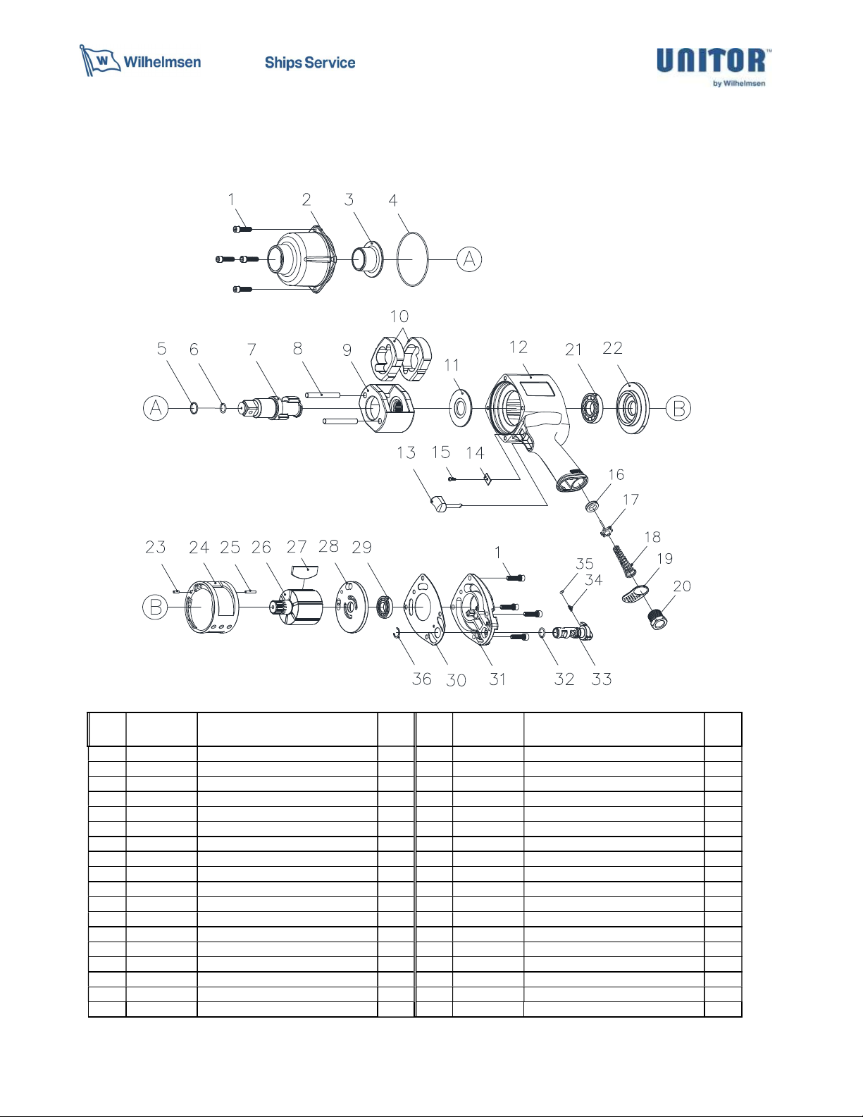
4.4.3 Remove the hexagon socket head screw from hammer housing.
4.4.4 Take off the hammer housing, put grease in the impact system.
4.4.5 Assemble the hammer housing, tighten the hexagon socket head screw.
4.4.6 Reconnect the air supply to the impact wrench and run for 20 to 30 seconds.

Page 8 of 11 Revision: CT/Feb-/2020
5. General Troubleshooting Guide
Symptom Possible Cause(s) Corrective Action
Tool runs slowly or
will not operate
1. Grit or gum in tool.
2. No oil in tool.
3. Low air pressure.
4. Air hose leaks.
5. Pressure drops.
6. Worn ball bearing
in motor.
1.Flush the tool with air tool oil, gum solvent,
or an equal mixture of SAE # 10 motor oil
and kerosene. Lubricate the tool after
cleaning.
2.Lubricate the tool according to the lubrication
instructions in this manual.
3.Adjust the compressor regulator to tool
maximum while the tool is running free.
4.Tighten and seal hose fittings if leaks are
found.
5-1.Be sure the hose is the proper size.
Long hoses or tools using large volumes of
air may require a hose with an I.D. of 10
mm (3/8") or larger depending on the total
length of the hose.
5-2.Do not use a multiple number of hoses
connected together with quick connect
fittings. This causes additional pressure
drops and reduces the tool power Directly
connect the hoses together.
6.Remove and inspect bearing for rust, dirt
and grit or worn race. Clean and regress
bearing with bearing grease.

Page 9 of 11 Revision: CT/Feb-/2020
Symptom Possible Cause(s) Corrective Action
Moisture blowing
out of tool
1.Water in tank.
2.Water in the air
lines/hoses.
1.Drain tank. (See air compressor manual).
Oil tool and run until no water is evident.
Oil tool again and run 1-2 seconds.
2-1.Install a water separator/filter.
Note: Separators only work properly
when the air passing through the
separator is cool. Locate the
separator/filter as far as possible from
the compressor.
2-2.Install an air dryer.
Impacts slowly or
Will not impact
1.Lack of lubrication.
2.Tool regulator set in
wrong position.
3.In-line regulator or
compressor regulator
set too low.
1.Lubricate the air motor and the impact
mechanism.(See lubrication section of
this manual)
2.Adjust the regulator setting of the tool.
3.Adjust regulators in the air system.
Impacts rapidly
But will not remove bolts
1.Worn impact
mechanism.
1-1 Replace impact mechanism.
1-2 Return impact wrench to your supplier for repair.
Does not impact 1.Worn impact
mechanism.
1-1 Replace impact mechanism.
1-2 Return impact wrench to your supplier for repair.

Page 10 of 11 Revision: CT/Feb-/2020
6. Impact Wrench IW-PRO 3/4" NG
REF
NO.
PARTS NO.
DESCRIPTION Q‘TY REF
NO.
PARTS NO. DESCRIPTION Q‘TY
1 T5266A-01 SCREW 8 19 T5266A-19 EXHAUST DEFLECTOR 1
2 T5266A-02 HAMMER HOUSING 1 20 T5266A-20 INLET BUSHING 1
3 T5266A-03 ANVIL BUSHING 1 21 T5266A-21 BALL BEARING 1
4 T5266A-04 “O” RING 1 22 T5266A-22 FRONT END PLATE 1
5 T5266A-05 SOCKET RETAINER 1 23 T5266A-23 SPRING PIN 1
6 T5266A-06 RETAINER “O” RING 1 24 T5266A-24 CYLINDER 1
7 T5266A-07 ANVIL (3/4”) 1 25 T5266A-25 SPRING PIN 1
8 T5266A-08 HAMMER PIN 2 26 T5266A-26 ROTOR 1
9 T5266A-09 HAMMER CAGE 1 27 T5266A-27 ROTOR BLADE 6
10 T5266A-10 HAMMER DOG 2 28 T5266A-28 REAR END PLATE 1
11 T5266A-11 HAMMER FRAME SPACER 1 29 T5266A-29 BALL BEARING 1
12 T5266A-12 MOTOR HOUSING 1 30 T5266A-30 GASKET 1
13 T5266A-13 TRIGGER 1 31 T5266A-31 HOUSING CAP 1
14 T5266A-14 TRIGGER RETAINER 1 32 T5266A-32 “O” RING 1
15 T5266A-15 SCREW 1 33 T5266A-33 REVERSE VALVE 1
16 T5266A-16 THROTTLE BUSHING 1 34 T5266A-34 SPRING 1
17 T5266A-17 VALVE STEM 1 35 T5266A-35 STEEL BALL 1
18 T5266A-18 SPRING 1 36 T5266A-36 RETAINER 1
Others Spare Part Kit: Air Motor Overhaul Kit F/IW-PRO 3/4” NG 407-722220

Page 11 of 11 Revision: CT/Feb-/2020
Attention
Please use these Unitor products exclusively for the purpose indicated by
WSS and only if the operator fully understands current practices
and procedures. If any further information or assistance is required
please contact your local WSS specialist.
www.wilhelmsen.com
Table of contents
Popular Power Tools manuals by other brands

Jet
Jet JWS-20CS Operating instructions and parts manual

PREMIUM BALLON ACCESSORIES
PREMIUM BALLON ACCESSORIES Cool Aire 4 manual

SPERO
SPERO SP 52 Translation from the original instruction manual

Siemens
Siemens SCALANCE M804PB operating instructions

Weber mt
Weber mt CF-2 HD Operating and maintenance manual

Hilti
Hilti DD 160 operating instructions

TYROLIT Hydrostress
TYROLIT Hydrostress HCE150 Original Operating Instruction

Stahlwille
Stahlwille Standard Manoskop 720 Nf/80 instructions

Bauer
Bauer 1826E-B user manual

FINO
FINO 10620 operating instructions

Alpha tools
Alpha tools AOF 1100E operating instructions

Hitachi
Hitachi CG 10DL Handling instructions