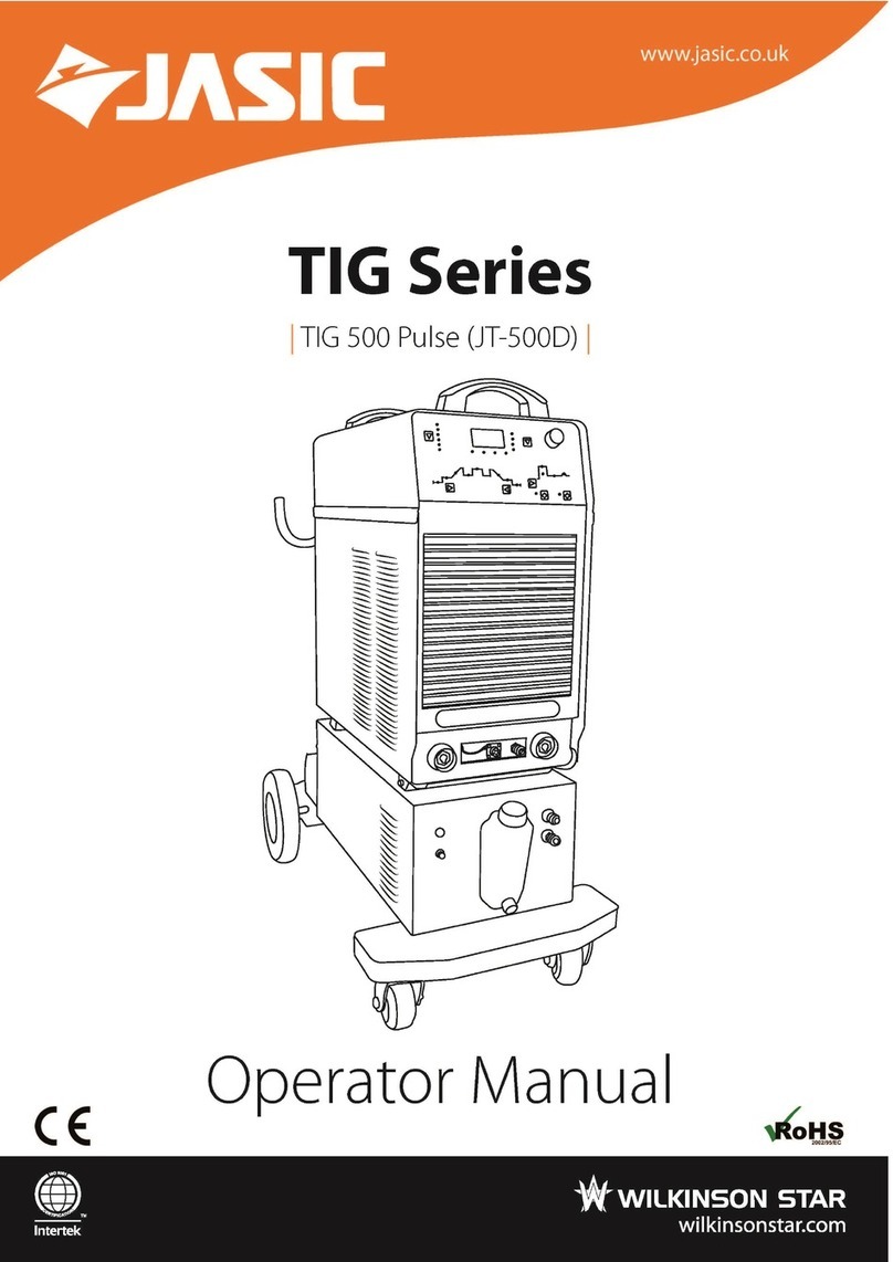
Wilkinson Star Jasic TIG Series User manual

A WILKINSON STAR LIMITED PRODUCT 06-16 ISSUE 2

A WILKINSON STAR LIMITED PRODUCT 06-16 ISSUE 2
Secon Title Page
1Your new product 3
2Safety 4
3Product overview 6
4Panel layouts 7
5Control panel funcons 8
6Unpacking 11
7Input and output connecons 11
8MMA Welding 11
9TIG Welding 13
10 Maintenance and troubleshoong 16
11 Technical Parameters 19
Contents

A WILKINSON STAR LIMITED PRODUCT 06-16 ISSUE 2
Thank you for selecng this Jasic Technology, Wilkinson Star product.
This product manual has been designed to ensure that you get the most from your new product. Please
ensure that you are fully conversant with the informaon provided paying parcular aenon to the
safety precauons. The informaon will help protect yourself and others against the potenal hazards
that you may come across.
Please ensure that you carry out daily and periodic maintenance checks to ensure years of reliable and
trouble free operaon.
Wilkinson Star Limited are a leading supplier of equipment in the UK and our products are supported by
our extensive service network. Call your distributor in the unlikely event of a problem occurring. Please
record below the details from your product as these will be required for warranty purposes and to
ensure you get the correct informaon should you require assistance or
spare parts.
Date purchased ________________________________________
From where ________________________________________
Serial Number ________________________________________
(The serial number will normally be located on the equipment data plate on the top or underside of the
machine )
Disclaimer
Whilst every eort has been made to ensure that the informaon contained within this manual is
complete and accurate, no liability can be accepted for any errors or omissions. Please note products are
subject to connual development and may be subject to change without noce.
This manual should not be copied or reproduced without the wrien permission of Wilkinson Star
Limited

A WILKINSON STAR LIMITED PRODUCT 06-16 ISSUE 2
These general safety norms cover both arc welding
machines and plasma cung machines unless
otherwise noted.
The equipment must only be used for the purpose
it was designed for. Using it in any other way could
result in damage or injury and in breach of the
safety rules.
Only suitably trained and competent persons
should use the equipment. Operators should
respect the safety of other persons.
The equipment should be installed by a qualied
person and in accordance with current standards in
operaon. It is the users responsibility to ensure
that the equipment is connected to a suitable
power supply. Consult with your ulity supplier if
required
If earth grounding of the work piece is required,
ground it directly with a separate cable.
Do not use the equipment with the covers
removed.
Do not touch live electrical parts or parts which are
electrically charged.
Turn o all equipment when not in use.
Cables (both primary supply and welding) should
be
regularly checked for damage and overheang. Do
not use worn, damaged, under sized, or poorly
jointed cables.
Ensure that you wear the correct protecve
clothing, gloves, head and eye protecon.
Insulate yourself from work and ground using dry
insulang mats or covers big enough to prevent
any physical contact with the work ground.
Never touch the electrode if you are in contact
with the work ground, or another electrode from a
dierent machine.
Do not wrap cables over your body.
Ensure that you take addional safety precauons
when you are welding in electrically hazardous
condions such as damp environments, wearing
wet clothing, and metal structures. Try to avoid
welding in cramped or restricted posions.
Ensure that the equipment is well maintained.
Repair or replace damaged or defecve parts
immediately. Carry out any regular maintenance in
accordance with the manufacturers instrucons.
Locate the equipment in a well-venlated posion.
Keep your head out of the fumes. Do not breathe
the fumes.
Ensure the welding zone is in a well-venlated
area. If this is not possible provision should be
made for suitable fume extracon.
If venlaon is poor, wear an approved respirator.
Read and understand the Material Safety Data
Sheets (MSDS’s) and the manufacturer’s
instrucons for metals, consumable, coangs,
cleaners, and de-greasers.
Do not weld in locaons near any de-greasing,
cleaning, or spraying operaons. Be aware that
heat and rays of the arc can react with vapours to
form highly toxic and irritang gases.
Do not weld on coated metals, unless the coang is
removed from the weld area, the area is well
venlated, and while wearing an air-supplied
respirator. The coangs on many metals can give
o toxic fumes if welded.
Arc rays from the welding process produce intense,
visible and invisible (ultraviolet and infrared) rays
that can burn eyes and skin.
Wear an approved welding helmet ed with a
proper shade of lter lens to protect your face and
eyes when welding or watching.

A WILKINSON STAR LIMITED PRODUCT 06-16 ISSUE 2
Wear approved safety glasses with side shields
under your helmet.
Never use broken or faulty welding helmets.
Always ensure there are adequate protecve
screens or barriers to protect others from ash,
glare and sparks from the welding area. Ensure
that there are adequate warnings that welding or
cung is taking place.
Wear suitable protecve ame resistant clothing.
The sparks and spaer from welding, hot work
pieces, and hot equipment can cause res and
burns
Welding on closed containers, such as tanks,
drums, or pipes, can cause them to explode.
Accidental contact of electrode to metal objects
can cause arcs, explosion, overheang, or re.
Check and be sure the area is safe and clear of
inammable material before carrying out any
welding.
Some welding and cung operaons may produce
noise.
Wear safety ear protecon to protect your hearing.
When the machine is in operaon keep away from
moving parts such as motors and fans. Moving
parts, such as the fan, may cut ngers and hands
and snag garments.
Protecons and coverings may be removed for
maintenance and controls only by qualied
personnel, aer rst disconnecng the power
supply cable.
Replace the coverings and protecons and close all
doors when the intervenon is nished, and before
starng the equipment.
Take care to avoid geng ngers trapped when
loading and feeding wire during set up and
operaon.
When feeding wire be careful to avoid poinng it at
other people or toward your body.
Always ensure machine covers and protecve
devices are in operaon.
Avoid causing res due to sparks and hot waste or
molten metal
Ensure that appropriate re safety devices are
available near the cung / welding area.
Remove all ammable and combusble materials
from the cung / welding zone and surrounding
areas
Do not cut/weld fuel and lubricant containers, even
if empty.
These must be carefully cleaned before they can be
cut/ welded.
Always allow the cut/welded material to cool
before touching it or placing it in contact with
combusble or ammable material.
Do not work in atmospheres with high
concentraons of combusble fumes, ammable
gases and dust.
Always check the work area half an hour aer
cung to make sure that no res have begun.
The magnec elds created by high currents may
aect the operaon of pacemakers or
electronically controlled medical equipment.
Wearers of vital electronic equipment should
consult their physician before beginning any arc
welding, cung, gouging or spot welding
operaons.
Do not go near welding equipment with any
sensive electronic equipment as the magnec
elds may cause damage.
Equipment that complies with direcve 2004/108/
EC concerning electromagnec compability (EMC)

A WILKINSON STAR LIMITED PRODUCT 06-16 ISSUE 2
and the technical requirements of EN60974-10 is
designed for use in industrial buildings and not
those for domesc use where electricity is provided
via the low voltage public distribuon system.
Dicules may arise in assuring class A
electromagnec compability for systems installed
in domesc locaons due to conducted and
radiated emissions.
In the case of electromagnec problems, it is the
responsibility of the user to resolve the situaon. It
may be necessary to shield the equipment and t
suitable lters on the mains supply.
Consult the data plate on the equipment for the
power supply requirements.
Due to the elevated absorbance of the primary
current from the power supply network, high power
systems aect the quality of power provided by the
network. Consequently, connecon restricons or
maximum impedance requirements permied by
the network at the public network connecon point
must be applied to these systems.
In this case the installer or the user is responsible
for ensuring the equipment can be connected,
consulng the electricity provider if necessary.
The equipment is manufactured with materials,
which do not contain any toxic or poisonous
materials dangerous to the operator.
When the equipment is scrapped, it should be
dismantled separang components according to the
type of materials.
Do not dispose of the equipment with normal
waste. The European Direcve 2002/96/EC on
Waste Electrical and Electronic Equipment states
the electrical equipment that has reached its end of
life must be collected separately and returned to an
environmentally compable recycling facility.
All cylinders and pressure regulators used in
welding operaons should be handled with care.
Never allow the electrode, electrode holder or any
other electrically “hot” parts to touch a cylinder.
Keep your head and face away from the cylinder
valve outlet when opening the cylinder valve.
Always secure the cylinder safely
Welding modes: DC TIG, Pulse TIG, DC MMA
Operang modes: Spot welding, 2T, 4T, Repeat
Equipped with HF and contact arc ignion.
MMA is equipped with an-sck and VRD.
Program storage in selected channels.
Energy saving intelligent cooling fan.
Advanced IGBT inverter technology
Digital MCU control mode
User friendly control panel
Can be used for a wide range of applicaons

A WILKINSON STAR LIMITED PRODUCT 06-16 ISSUE 2
No. Part name
1Protecve bar for front panel
2Scker on front panel
3Socket for the torch switch
4Socket for remote control
5“+” output terminal
6Rotary knob
7Gas outlet
8“-” output terminal
No. Part name
1Cable inlet
2Fuse holder
3Gas inlet
4Rubber foot
5Fan grill
6Back panel plasc enclosure
7Power switch

A WILKINSON STAR LIMITED PRODUCT 06-16 ISSUE 2
1. Welding mode selecon zone
2. TIG welding parameters selecon zone
3. TIG welding mode selecon zone
4. MMA welding parameters selecon zone
5. Parameters adjustment rotary knob
6. Channel selecon buon
7. Parameters and protecon indicaon display zone
FUNCTIONS
Welding mode selecon zone contains welding
mode indicators and selecon key.
Welding modes include DC TIG, Pulse TIG, DIC
MMA(TIG400 has no pulse TIG funcon). Press the
welding mode selecon key to choose the
according welding mode. The welding mode being
selected LED will be lit when selected and there is
welding current owing.

A WILKINSON STAR LIMITED PRODUCT 06-16 ISSUE 2
This zone contains parameters selecon and VRD
switch-over
1.Press to switch MMA parameters; it can be
circulated among HOT START、CURRENT、ARC
FORCE
2.Press VRD and indicator is on; MMA will enter
VRD mode and OCV is 19V.
This zone contains display, parameters unit
indicator, warning indicator.
1. The window in the middle is a display to show
all parameters.
2. O.C on the le is over current protecon
indicator; O.H is over heat protecon indicator.
3. A、S、%、Hz on the right are parameters’
unit of current, me (second), duty cycle, HZ
respecvely.
This zone include 3 parts: TIG operang mode
selecon, water cooling switch key, arc ignion
switch key ( HF& contact)
1. TIG welding modes: 2T、4T、REPEAT、SPOT,
Press
to select the according welding mode.
2.TIG water cooling witch key
(1)press the key and indictor is on to enter water
cooling mode. In full set welding system, water
tank will give water ow signal and check whether
there is a water-lack; there is E-5 warning and is
with no output in case of water lack; please check
if everything is back to normal and observe
whether there is E-5 when under TIG.
(2)Every me operator presses this key, the gas
valve will work. Therefore, it can be used as gas
detecon.
3.Arc ignion type selecon.
(1)press this key and indicator is on to enter HF
arc ignion.
(2)press this key and indicator is o to enter li
arc ignion. When in this mode, place the torch to
contact workpiece; pull torch trigger then li the
torch slowly to achieve arc ignion.

A WILKINSON STAR LIMITED PRODUCT 06-16 ISSUE 2
1. Press to circulate clockwise and select the
chosen TIG parameter.
2. Parameter descripon:
Tpre—Pre-ow me Is—Inial current
Tup—Up-slope me Ip—Peak current
Ib—Base current Tdown—Down-slope me
If—Final current Tpost—Post-ow me
Hz—Pulse frequency %--Pulse duty factor
Tspot—Spot welding me
Ib、Hz、% when in
Ip is welding current.
Parameter adjustment rotary knob is
for all welding parameter seng.
For simple and ecient welding
processing, this machine is equipped
with 8 welding parameters storage
channels for DC TIG, Pulse TIG and DC
MMA.
The so-called channel is operator’s processing
specicaon plaorm (it contains welding funcon,
welding current, operang mode and other
parameters related with processing.) This machine
is working in certain channel when it’s powered on
and the channel it’s located in is the previous
working channel when the machine is turned o.
Check the channel number: press the channel key
when machine is under standby and the display
window will show the current working channel.
E.g.. When the current working channel is #6, then
the display will show “CH-6”.
To change the channel number: press the channel
key when machine is under standby and the display
window will show the current working channel.
Then adjust the rotary knob to change the working
channel from 1`8.
Exit channel management: re-press the CH key to
exit channel management.
Loading channel parameters :press the channel
key when machine is under standby and the display
window will show the current working channel.
Then adjust the rotary knob to change the working
channel from 1`8. Re-press the CH key aer
selecng the required channel number and system
will show all the parameters under this channel for
operator’s usage.
Channel parameters’ storage: aer choosing the
required channel number and adjusng the
required welding parameters, the operator has to
start welding process to save the current
parameters.
:
’
The water cooler panel includes WORK indicator,
fuse,OUTPUT quick connector and INPUT quick
connector.
1. When WORK indicator is on, it means water
cooler is in operaon; when indicator is o, it
means water cooler is not working.
2. The water cooler operaon status is controlled
by the machine power source. When machine
power source is under TIG water cooling, which is

A WILKINSON STAR LIMITED PRODUCT 06-16 ISSUE 2
to say, the indicator is on, the opons
are:
(1)when there is current output from power
source, water cooler the WORK indicator is on.
(2)when the preset current is lower than 250A
and also there is no current output, the water
cooler will stop working aer 2 minutes and WORK
indicator will be o.
(3)when preset current is higher than 250A and
also there is no current output, the water cooler
will stop working aer 4 minutes and WORK
indicator will be o.
(4)when there is no water ow and also there is
no current output, the water cooler will stop
working aer 10 minutes and WORK indicator will
be o.
3. FUSE—The fuse rang is 5A.
4. OUTPUT (supply) quick connector has a blue
base and is connected to the water supply hose of
the welding torch (the torch’s blue quick
connector).
5. INPUT (return) quick connector has a red base
and is to connected water cooling return—
normally the torch power cable (the torch’s red
quick connector).
Check the packaging for any signs of damage.
Carefully remove the machine and retain the
packaging unl the installaon is complete.
The machine should be located in a suitable
posion and environment. Care should be taken to
avoid moisture, dust, steam, oil or corrosive gases.
Place on a secure level surface and ensure that
there is adequate clearance around the machine to
ensure natural airow.
Before connecng the machine you should ensure
that the correct supply is available. Details of the
machine requirements can be found on the data
plate of the machine or in the technical parameters
shown in the manual.
The equipment should be connected by a suitably
qualied competent person. Always ensure the
equipment has a proper grounding. Never connect
the machine to the mains supply with the panels
removed.
Electrode polarity
In general when using manual arc welding
electrodes the electrode holder is connected the
the posive terminal and the work return to the
negave terminal. Always consult the electrode
manufacturer’s data sheet if you have any doubts.
When using the machine for TIG welding the TIG
torch should be connected to the negave terminal
and the work return to the posive terminal.
Insert the cable plug with electrode holder into the
“+” socket on the front panel of the welding
machine, and ghten it clockwise. Insert the cable
plug of the work return lead into the “-”ve socket
on the front panel of the welding machine, and
ghten it clockwise

A WILKINSON STAR LIMITED PRODUCT 06-16 ISSUE 2
Switch the welding mode switch on the front panel
of the welding machine to “MMA” posion.
Turn on the power switch of the welding machine.
Then, the cooling fan will work, and the current
meter will display the preset welding current.
Adjust the welding parameters to the appropriate
values according to the welding requirements.
Aer the above steps are nished, welding can be
carried out. The current meter will display the actual
welding current when the arc is established
Aenon: This machine is equipped with an-
scking funcon. When arc voltage is too low and a
short circuit occurs the machine output is reduced
to 10A to prevent the electrode scking enabling it
to be broken away easily.
For more details always consult the electrode
material data sheet
Note: This table is suitable for mild steel welding. For other materials,
consult related materials and welding process for reference.
Adjustable
parameter
Adjusng
range Descripon
Arc ignion
current 0~200A
When the selected arc ignion
current is lower than the
welding current, it will output
the welding current
automacally when igning arc;
when the selected arc ignion
current is higher than the
welding current, it will output
the arc ignion current when
igning arc. If the arc ignion arc
is overly low, it is hard to ignite
arc and the success rate in arc
ignion is low; if the arc ignion
current is overly high, the
workpiece will be easily burned
through. Therefore, the arc
ignion current should be set
properly according to praccal
Welding
current 30~400A The output current for stable
welding.
Arc force
current 0~200A
If the arc force current is overly
low, electrode scking will occur
during welding and the arc is
weak; if the arc force current is
overly high, excessive spaer
will be caused. Therefore, the
arc force current should be set
properly according to praccal
Electrode
diameter (mm)
Recommended welding
current (A)
1.0 20~60
1.6 44~84
2.0 60~100
2.5 80~120
3.2 108~148
4.0 140~180
5.0 180~220
6.0 220~260

A WILKINSON STAR LIMITED PRODUCT 06-16 ISSUE 2
Insert the cable plug with the work clamp into the
“+” socket on the front panel of the welding
machine, and ghten it clockwise. Insert the cables
plug of the TIG torch into the “-” socket on the front
panel of the machine and ghten clockwise.
Connect the gas quick connector into the outlet on
the machine front.
Connect the torch switch plug into the socket on
the front panel.
Connect the gas hose to the regulator / owmeter
located on the shield gas cylinder and connect the
other end to the machine.
Switch the welding mode switch on the front panel
of the welding machine to “TIG” or “Pulse” posion.
Turn on the power switch of the welding machine.
Then, the cooling fan will work, and the current
meter will display the preset welding current.
Turn the gas-check/welding switch to “gas-check”
posion, and adjust the gas ow control knob on
the gas regulator to get the desired gas ow. Aer
that, turn the gas-check/welding switch to
“welding” posion.
Select the required operaon mode via the 2T/
repeang/4T / spot switch according to the welding
requirements.
Adjust the welding parameters to the appropriate
values according to the welding requirements.
Aer the above steps are nished, welding can be
carried out. The current meter will display the
actual welding current.
There are 4 operaon modes, namely 2T, 4T and

A WILKINSON STAR LIMITED PRODUCT 06-16 ISSUE 2
repeang are available for this machine in TIG
welding.
The adjustable TIG parameters are below.
In 2T mode, the gas valve opens aer the torch
switch is pressed down. Aer the pre-ow me
ends, discharge begins to ignite arc, and then the
current rises up to the welding current value
gradually. When the torch switch is released, the
current begins to drop gradually. When it drops to
the pilot arc current value, the current output is cut
o. The gas valve closes when the post-ow me
ends, and the welding process ends.
If the torch switch is pressed down during the
current downslope process, the current will rise up
to the welding current value, waing for the torch
switch to be released again.
In 4T mode, the gas valve opens aer the torch
switch is pressed down. Aer the pre-ow me
ends, HF discharge begins to ignite arc. Aer arc is
ignited successfully, the inial current is output.
Aer the torch switch is released, the current rises
up to the welding current value gradually and holds
there with the torch switch released. When the
torch switch is pressed down again, the current
begins to drop gradually to the pilot arc current
value. When the torch switch is released again, the
current output is cut o. Gas ows for the post ow
me
Adjustable
parameter
Adjusng
range Descripon
Pre-ow
me 0~15s
It is suggested to adjust it to
1s or an appropriate value
according to welding
requirements.
Post-ow
me 0~15s
It is suggested to adjust it to
5s or an appropriate value
according to welding
requirements.
Inial
current 5~100A
It is suggested to adjust it to
about 50% of the welding
current or an appropriate
value according to welding
requirements.
Up slope 0~10s To adjust the up slope me.
Welding
current 5~400A To adjust the welding current
in DC TIG and to adjust the
Pulse
duraon
rao
10~90%
To adjust the percentage the
peak current holding in a
period in pulse TIG. Please set
it according to praccal
welding requirements.
Base
current 5~400A To adjust the base current
value in pulse TIG.
Pulse
frequency 0.5~200Hz
To adjust pulse frequency. The
rst half of the knob is low
frequency range within
0.2~10Hz, and the second half
of the knob is high frequency
Downslope 0~10s To adjust the downslope me.
Pilot arc
current 5~400A
It is suggested to adjust it to a
lower value or an appropriate
value according to welding
requirements.

A WILKINSON STAR LIMITED PRODUCT 06-16 ISSUE 2
In repeang mode, the gas valve opens aer the
torch switch is pressed down. Aer the pre-ow
me ends, discharge begins to ignite arc. Aer arc
is ignited successfully, the pilot arc current is
output. Aer the torch switch is released, the
current rises up to the welding current value
gradually. When the torch switch is pressed down
again, the current begins to drop gradually to the
pilot arc current value. When the torch switch is
released again, the current rises up to the welding
current value gradually again. “Repeang” means
the welding current varies between the pilot arc
current value and the welding current value.
To exnguish arc, please keep the torch away
from workpiece to increase arc voltage, the arc
can be exnguished immediately and the current
output will be cut o. The gas valve closes when
the post-ow me ends, and the welding process
ends.
In spot welding mode discharge begins to ignite
arc aer the torch switch is pressed down. Aer
arc is ignited successfully, the welding current is
output . Now no maer if the torch switch is on or
o, the machine will sll output welding current.
When the spot welding me you have set is
over ,the arc will be exnguished. The gas valve
closes when the post-ow me ends, and the
welding process ends.
HF arc ignion is available for the above four
modes. This welder is also equipped with li arc
ignion. In this mode the tungsten is touched to
the work piece, the torch trigger operated and a
very low current ows. When the tungsten is lied
from the work piece the current will rise to the set
condion. Compared to HF ignion though it is
more dicult to get correct as many welders are
taught not to touch the electrode to the work
piece. Li arc ignion is not available in the spot
welding mode.
Shut o the cylinder valve and drain the gas in the
system. Turn of the power of the welding machine
3~5min aer the welding work is nished, so as to
cool the internal components of the machine.
Turn o the power switch on the welding machine
and then switch o the power at the mains
switching box.
Please do not dispose of electrical waste with
normal waste products. In accordance with the
European direcve 2002/96/EC regarding waste
electrical and electronic equipment and its
implementaon into naonal law any electrical or
electronic which has reached its end of life must
be collected separately and disposed of via a
suitable recycling facility.
The owner of the equipment is required to return
the equipment to a suitable recycling facility or to
Wilkinson Star Limited for the correct recycling of
the product.

A WILKINSON STAR LIMITED PRODUCT 06-16 ISSUE 2
In order to guarantee that the arc welding machine
works eciently and in safety, it must be
maintained regularly. Operators should understand
the maintenance methods and means of arc
welding machine operaon. This guide should
enable customers to carry on simple examinaon
and safeguarding by oneself, try to reduce the fault
rate and repair mes of the arc welding machine, so
as to lengthen service life of arc welding machine.
Items Checking requirements Remarks
Front
panel
Whether any of the
components are damaged or
loosely connected;
Whether the cables at the
boom are ghtly connected;
Whether the abnormity
indicator illuminates aer
starng the machine.
If qualied,
check the
interior of the
machine, and
ghten or
replace the
components.
Back
panel
Whether the input power
cable is in good condion;
Whether the air intake is
unobstructed.
Cover
Whether the handle is
damaged or loosely
connected.
If qualied,
ghten or
replace the
components.
Chassis
Whether any chassis
components are damaged or
loose
Fan
Whether the fan or fan guard
is distorted or damaged.
Whether the fan works or
sounds normal when the
machine is running;
If abnormal,
eliminate the
failures or
replace the
fan.
Gas
hose
Whether the gas hose joints
are ght and whether the gas
hose is damaged.
Tighten the
hose joints or
replace the
gas hose.
All maintenance and checking should be carried out
aer the power is completely cut o. Make sure the
power plug of the machine is pulled out before
uncovering the welding machine.
When the machine is powered on, keep hands, hair
and tools away from the moving parts such as the
fan to avoid personal injury or machine damage.
Check periodically whether inner circuit connecon
is in good condion (esp. plugs). Tighten the loose
connecon. If there is oxidizaon, remove it with
sandpaper and then reconnect. Check periodically
whether the insulang layer of all cables is in good
condion. If there is any dilapidaon, rewrap it or
replace it.
In order to protect the semiconductor components
and PCBs from the stac damage, please wear
anstac device or touch the metal part of the
enclosure to remove stac in advance before
contacng the conductors and PCBs of the machine
internal wiring.
Avoid rain, water and vapor inltrang the machine.
If there is, dry it and check the insulaon of the
welding machine (including that between the
connecons and that between the connecon and
the enclosure) with an ohmmeter. Only when there
are no abnormal phenomena anymore, can the
machine be used.
Put the machine into the original packing in dry
locaon if it is not to be used for a long me.
Periodic checks should be carried out to ensure the
long-term normal use of the machine. Be careful
when doing the periodic check, including the
inspecon and cleaning of the machine interior.
Generally, periodic check should be carried out
every 6 months, and it should be carried out every 3
months if the cung environment is dusty or with
heavy oily smoke.
Beware of corrosion
Please clean the plasc parts with neutral
detergent.

A WILKINSON STAR LIMITED PRODUCT 06-16 ISSUE 2
Before arc welding machines are dispatched from
the factory, they have already been checked
thoroughly. The machine should not be tampered
with or altered. Maintenance must be carried out
carefully. If any wire becomes loose or is misplaced,
it maybe potenal danger to user!
Only professional maintenance personnel should
repair the machine!
Ensure the power is disconnected before working
on the machine. Always wait 5 minutes aer power
switch o before opening the case.
There are indicator alarms and meter alarm
funcons available for this machine when a
machine failure occurs.
When over current occurs, the over current
indicator on the front panel will illuminate and the
meter on the front panel will display “E-0”
When overheang occurs, the overheang
indicator on the front panel will illuminate and the
meter on the front panel will display “E-3”
When a problem occurs with the water cooling
system the meter on the front panel will display “E
– 5”

A WILKINSON STAR LIMITED PRODUCT 06-16 ISSUE 2
Phenomena Cause Soluon
The fan does not work or works abnormally
and the meter does not display aer the
machine is started.
Phase failure of the mains power supply
or the power cable is not well
connected.
Solve the phase failure problem or reconnect
the power cable.
MMA
Hard to ignite arc The arc ignion current is too low or the
arc ignion me is too short.
Increase the arc ignion current or prolong
the arc ignion me properly.
Excessive spaer or
the molten pool is too
big.
The arc ignion current is too high or the
arc ignion me is too long.
Reduce the arc ignion current or shorten the
arc ignion me properly.
Normal arc can not be
started.
Phase failure of the mains power supply
or the power cord is not well connected.
Solve the phase failure problem or reconnect
the power cable.
Electrode scking The arc force current is too low. Increase the arc force current properly.
The electrode holder
becomes very hot.
The rated current of the electrode
holder is smaller than its actual working
current.
Replace it with a bigger rated current.
TIG
There is no current
output when pressing
down the torch
switch.
The torch switch circuit fails. Check the torch switch circuit.
The welding circuit is not in good
connecon.
Check the welding circuit and reconnect it if
necessary.
There is no HF
discharge when
pressing down the
torch switch in HF arc
ignion mode.
The torch switch is not connected well. Connect the torch switch well.
The HF discharge nozzle gap is too big. Adjust the discharge nozzle gap to about
1.0mm.
The electrode burns
quickly in TIG welding.
The output polarity connecon is
incorrect. Exchange the polarity.
TIG
Black weld bead The weld bead is not well protected and
is oxidized.
Make sure the gas valve of the cylinder is
open and the pressure inside the cylinder is
high enough. Generally, it is necessary to rell
the cylinder when the pressure is lower than
0.5MPa.
Check if the gas ow is normal. You may
select dierent gas ow according dierent
welding current. However low the current is,
the gas ow is recommended to be not less
than 5L/min. Otherwise, the weld bead may
not be fully covered for lack of shielded gas.
Check if the gas path is airproof and if the gas
is pure enough.
Check if the environment is with strong wind.
Arc is hard to start but
easy to break.
The electrode you use is of poor quality
or is badly oxidized.
Replace it with electrode of beer quality.
Remove the oxidized layer of the electrode.
Prolong the post-ow me to avoid
oxidizaon of the electrode.
Adjust the spark gap on the discharge board
to about 1.0mm.
Unstable current
during welding
Mains voltage uctuates badly, or the
input cable is loosely connected with the
mains power supply.
Check the mains power supply for normal
state, and reconnect the power cable.
There is serious interference from other
electric appliances
Do not connect the machine to the power
cable which is connected to other electric
appliances of serious interference.
Other failures Contact the service centre of our company.
POSSIBLE MACHINE FAILURES

A WILKINSON STAR LIMITED PRODUCT 06-16 ISSUE 2
Parameters Model
TIG400P (W322)
Input
Rated input power supply Three-phase AC400V 50/60Hz
Rated input capacity (KVA) 17.9
Power factor 0.96
MMA output
Rated no-load voltage (V) 68( 15V when under VRD)
Rated maximum output (A/V) 400/36
Welding current range (A) 30~400
Arc force current range (A) 0~200
Arc ignion current range (A) 0~200
Output characterisc CC
TIG output
Rated maximum output (A/V) 400/26
Welding current range (A) 5~400
Pre-ow me range (s) 0~15
Inial current range (A) 5~400
Pilot arc current range (A) 5~400
Up slope me range (s) 0~10
Base current range (A) 5~400
Peak current range (A) 5~400
Downslope me range (s) 0~10
Post-ow me range (s) 0~15
Pulse frequency range (Hz) 0.5~200
Pulse duraon rao range (%) 10~90
Spot welding me 0.1~10
Arc ignion mode HF /Li arc ignion
Output characterisc CC
Environment
Working temperature range (0C) -10~+40
Storage temperature range (0C) -25~+55
Humidity (%) ≤90% (no water condensate)
Structure Enclosure ingress protecon IP21S
Cooling mode Forced air cooling
Rated duty cycle (%) MMA:30 TIG:50
Eciency (%) 85
Insulaon grade F
Overall size (L*W*H) 595*297*528
Weight (Kg) 30

A WILKINSON STAR LIMITED PRODUCT 06-16 ISSUE 2
-
Other manuals for Jasic TIG Series
1
This manual suits for next models
2
Table of contents
Other Wilkinson Star Welding System manuals