WH-2600 SERIES
PATIENT CARE UNITS INSTALLATION & OPERATION MANUAL
PAGE 10 © Rev. 2/2017
1.800.428.4065 TOLL FREE
| www.willoughby-ind.com
Step 6: Install the Stationary Lavatory Top
1.) Apply a bead of silicone caulk around the outer top edge of the fi xed cabinet and between the
lavatory top and the wall.
2.) Set the stationary lavatory top in place on the fi xed cabinet making sure the back is fl ush with
the wall. Clean up excess caulk around the countertop edge.
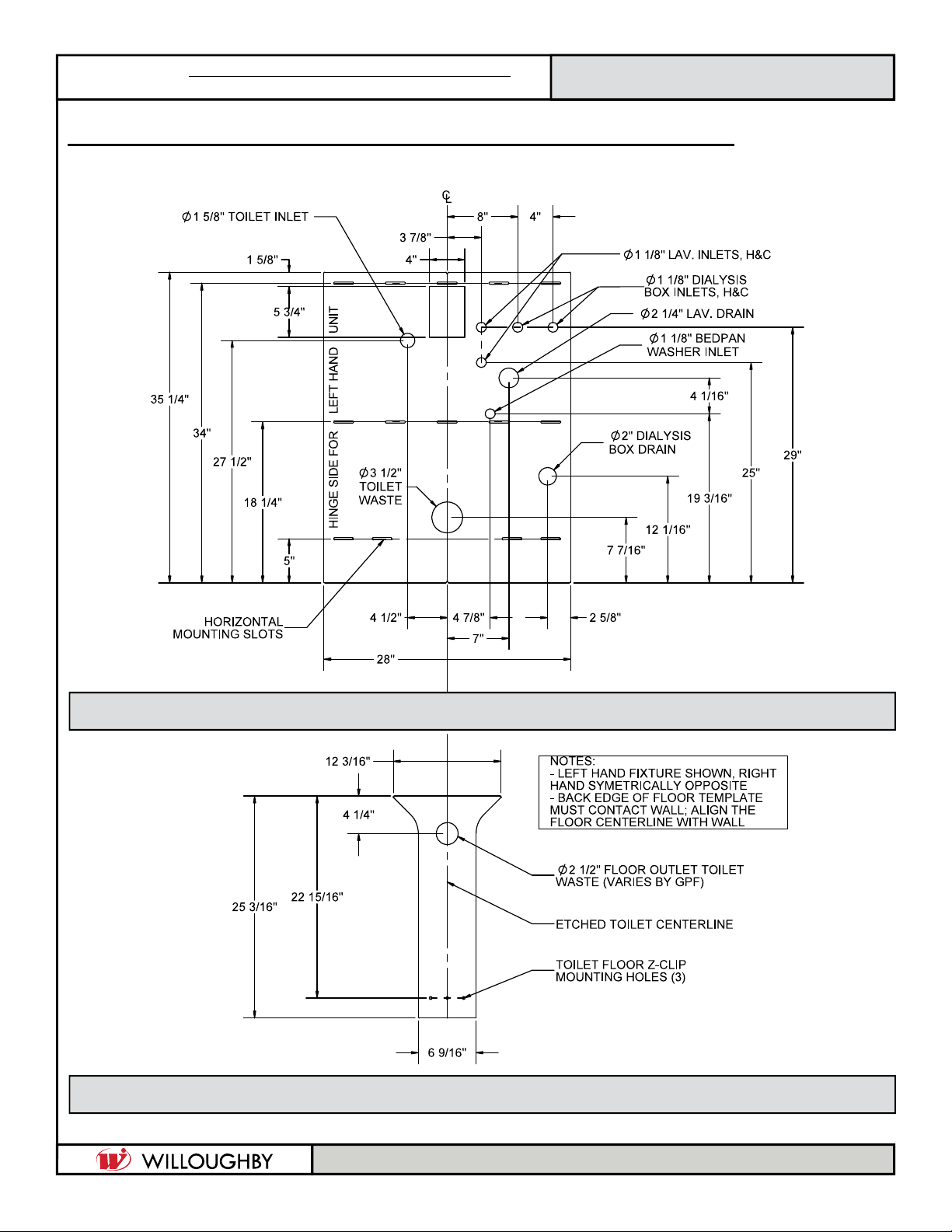
Step 5: Install the Toilet and Waste Connections
1.) Slide toilet into position over the fl oor Z-clip installed in Step 2.
2.) Connect the toilet to the fl oor/wall waste outlet with an appropriate gasket. Be sure to square
the toilet assembly to the back wall.
3.) Level and support the toilet solidly at the four corners using shims, if needed
(shims supplied by installer).
4.) Secure the toilet in place with appropriate hardware.
NOTE: If the waste outlet is through the back, use a no-hub type connector
(available as an option).
5.) On WH-2600 models with a back waste connection, tighten the connector clamps at this time.
INSTALLATION INSTRUCTIONS (CONT.)
Step 7: Install the Sink Lavatory Top to the Toilet Cabinet
1.) Install the drain assembly inside the sink lavatory top.
2.) Apply a bead of silicone caulk around the outer top edge of the toilet cabinet.
3.) With the swinging toilet cabinet closed, set the sink lavatory top in place on the cabinet making
sure the back of the sink latatory top is fl ush with the stationary lavatory top. Clean up excess
caulk around the countertop edge.