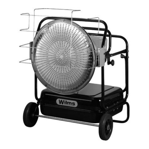
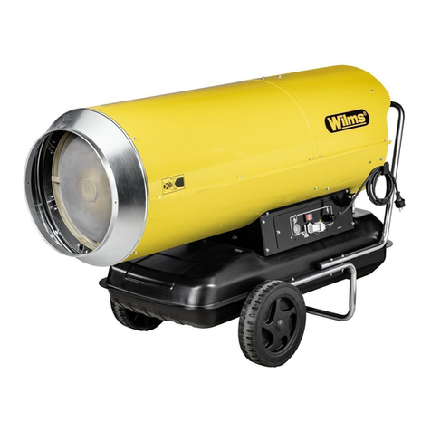
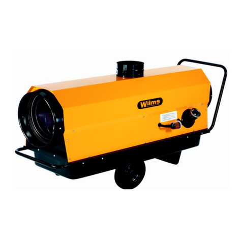
WILMS BV 385 User manual

Operating Manual
Oil Fired Heaters
BV 385
Perfection is our aim

EC –Declaration of Conformity
according to machine directive 2006 / 42 / EEC
appendix II A
Structure of the machine
Mobile oil-fired heaters ( with and without heat exchanger )
Description:
BV 385
is designed, constructed and manufactured in accordance with the above-
mentioned directive and the low voltage directive 2014 / 35 / EEC and also
EMV 2014 / 30 EEC.
The following harmonized standards have been used:
- DIN EN 6100-3-2 Electromagnetic compatibility
- EN 55011 Product standard for wideband interferences
- DIN EN ISO 12100 Safety of machinery
- DIN EN 60335-1 Safety of electrical appliances
- DIN EN ISO 13857 Safety of machinery, safety distances
Note: The observance of DIN EN ISO 13857 refers only to the protection against
accidental contacts of the fan. For the complete fulfillment of EN 13857 the user
resp. installer is responsible.
The following national standards, directives and specifications have been
used:
- DIN EN 13842 „Mobile oil-fired heaters ( with and without heat exchanger )“
Mönchengladbach,
17.04.2020 Managing Director
______________ ______________________ ____________________________
Place, Date Signature

Index Type BV 385 Page
Important Notice 1
To read before operating 2
Technical Specifications 3
1. How to start the heater 4
Attention 4
Operation „Heating“ 4
Operation „Ventilation“ 4
2. How to stop the heater 5
Important 5
3. Safety and control devices 5
Combi control 5
Room-thermostat 5
4. Transport 5
5. Cleaning 5
6. Trouble shooting 6
7. Important notice for set-up 7
8. Length and diameter of fuel lines 8
9. Service position 9
10. Nozzle change 9
11. Adjusting of electrodes 9
12. Adjusting of air flow measurement "B" and "A" 10
Pre-set values 11
Spare Parts List 12-13
Exploded view: Spare Parts List 14
Spare Parts List Burner 15
Exploded view: Spare Parts List Burner 16
Wiring diagram 17

Important Notice!
1. Use only clean (if possible filtered) Heizöl EL (Diesel).
2. Clean fuel filter regularly.
A T T E N T I O N :
Notice: Heizöl EL changes viscosity in low temperature.
Remedy: Use cerosine (petroleum) or mix Diesel and cerosine
(Heizöl / petroleum) 50 : 50.
This heater is standard equipped with a fuel preheating device. This
requires also during the heating interruptions (during the night, on
weekends) tension, so it remains effective. Therefore, leave the plug
into the socket, switch to position "Heizen" (Heating) and set the room
thermostat to a low temperature (frost protection) (230 V only).
When ordering spare parts please give the type, serial number of the
heater and the part number, otherwise a correct delivery is not
possible.
The admissible ambient temperature for securing the function of the
control is –15°C and max. + 50°C. This is to be especially taken
into consideration whilst drying grain or using the heater outdoors.
The heater resp. the flame control has to be protected against direct
influence from the bright sun light.
Technical specifications are subject to changes without any notice!
- 1 of 17 -

Read carefully before starting your heater!
IMPORTANT NOTICE
This unit is a space heater with indirect heating, heat exchanger and exhaust.
The heater may not be set up near explosive or flamable materials and may not
be used in explosion or fire endangered rooms. It may also not be used in areas with
high dust development. The heater should be positioned at adequate distance to
flamable material such as wood etc. It is essential that there is a sufficient ventilation
of the room. The heater may not be worked on or transported during operation.
If the heater is used for drying of grain the set-up has to be in a right angle in front
of the radial fan or alternatively with sufficient distance. This has to be done so that
the function of the heater is not influenced by the immense suction of the radial fan.
The heater is standard equipped with a fuel pre-heating device. This requires also
during the heating interruption (during the night, on weekends) tension so it remains
effective. Therefore leave the plug into the socket, switch to position "Heizen" (Heating)
and set the room thermostat to a low temperature (frost protection).
- 2 of 17 -

T E C H N I C A L D A T A
Type: BV 385
Voltage V/Hz 230/50
Rated current A 10,2
Nominal capacity kW 2,0
Protection IP 44
Capacity kW 110
kcal/h 94.600
Air volume m³ /h 8.200
Max. fuel consumption appr. kg/h 9,2
Dimensions L mm 1985
W mm 895
H mm 1385
Weight kg 305
Cone Ø mm 520
Chimney Ø mm 200
Photo cell standard
Room thermostat standard
for use in high humidity with 10 m cable
Noise level dB (A) 72
(EN ISO 11201)
- 3 of 17 -

1. How to start the heater
a) Fill a drum or a tank with clean Heizöl EL (Diesel) and set it up according to the
local regulation. Connect fuel intake and return line of the heater with the drum
or tank. Open the valve at the fuel filter.
b) Install exhaust system according to the drawing, see page 7.
c) If warm air hoses are used, avoid sharp bendings.
d) Power supply: Connect heater to the 230 V - 50 Hz power supply.
e) Put room thermostat on suitable place in the room and set to desired
temperature. (Must be above ambient temperature).
A T T E N T I O N
The heater is standard equipped with a fuel preheating device. The function of the
preheating is only given if the heater remains on stand-by with plugged-in electrical
plug for appr. 15-20 min. before the first starting.
During this time the oil is preheated so that the sorting out of paraffine is avoided.
Start the heater only with connected fuel hoses. Otherwise the fuel pump will be
destroyed.
During service always obbey the surface temperature from the fuel preheating
device. Disconnect the heater first from the power supply and let it cool down
(danger of burning).
Operation "Heating"
Set main switch to position "Heating" (Heizen).
The automatic heating operation is started when the switch is set to position "Heating"
(Heizen).
The oil burner starts and heats first the heat exchanger to appr. 35°C, only then the
fan starts and supplies immediately warm air.
Operation "Ventilation"
Set main switch to position "Ventilation" (Lüften).
In this case only the fan runs in continuous operation and blows cold air. Therefore the
heater can be used during the summertime for ventilation. The room thermostat does
not function during this kind of operation.
- 4 of 17 -

2. How to stop the heater
Set main switch to pos. "0".
If the heater has been running on position "Heating" (Heizen) it has an automatic
cooling of the heater until it completely shuts off.
Important!
Pull the main plug only after the heater has cooled down and stopped.
Before repairing or servicing always pull the main plug.
On operation "Ventilation" (Lüften) the unit shuts off immediately.
3. Safety and control devices
In case there is no flame - for example caused by lack of fuel - the oil burner relay
shuts off the heater. The control lamp on the side of the burner reset button lights up.
After the cause of the malfunction has been cleared the reset button can be pushed
after a waiting time of appr. 60 sec. and the burner can be restarted.
Combi control
The combi control is equipped with 3 temperature sensors which are straight in the
warm air stream.
The first sensor controls the starting retardation and the postpurge of the fan.
The second sensor controls the operation temperature. If the max. operating
temperature of 80° C is exceeded, the sensor shuts the burner off while the fan
continues to run for cooling.
The third sensor serves as a safety thermostat against overheating, for example in
case of malfunction of the fan.
After the cause of overheating has been eliminated the reset button of the safety
thermostat has to be pushed in order to restart the heater.
Room thermostat
The thermostat has a temperature regulation range of 5° C - 30° C and shuts the
burner off after the preset temperature has been reached. The fan continues to run
in order to cool the heater down to a temperature of appr. 30° C before it stops. After
the room temperature drops several °C the heater automatically starts running again.
4. Transport
The heater can be transported and is equipped with hooks for crane transportation.
These hooks are especially marked. Please use only these devices.
5. Cleaning
The heater should be cleaned minimum once a year. Therefore remove the lid of the
insert (Pos. 10 page 12).
- 5 of 17 -

Before repairing or servicing the heater pull the main plug!
Repair or service of electrical components may only be made by authorized
specialists!!!
6. Trouble Shooting
Fault Cause Remedy
Main switch on position No electricity. Check if there is power.
"Heating" (Heizen). Check main fuse.
Heater does not start. Setting of room Reset thermostat.
thermostat. The preset
temperature is lower than
the ambient temperature.
Safety thermostat Push reset button of
shuts off. safety thermostat.
Restart heater.
Burner starts shortly and Lack of fuel. Check fuel intake and
shutts off. The red lamp return line.
lights up. Air bubbles in the Check oil level in tank.
suction line. Check if the valve at the
fuel filter is opened.
Push reset button.
On initial start the burner Lack of fuel. Push the rest button until
runs shortly and shutts off. enough fuel is injected.
Air bubbles in the
suction line.
There is not enough
fuel.
Burner shuts off during Fuel filter dirty. Clean (replace) fuel
operation. filter.
Photo cell dirty. Clean the photo cell
carefully.
Safety thermostat shuts Sharp bendings in warm Use warm air hoses
off during operation. air hoses. properly. Push reset
button of safety
thermostat. Restart heater.
If your heater does not work properly in spite of these checks, call your nearest
service.
- 6 of 17 -

6. Important Notice
These units are oil fired space heaters, equipped with a chimney connection. If
connected to a chimney the installation should be made only according to the below
drawing.
The connection should be made only with a fixed chimney according to the regulations
or an installed exhaust pipe as shown in the drawing.
Never start the heaters connected to just an exhaust pipe which has been lead through
the wall.
Use it only with an additional exhaust pipe, minimum above the ridge. In case of
horizontal outlet through the wall, use only with T-shaped pipe, refer below drawing.
Top of exhaust pipe or chimney
should be 0,5 m above ridge.
Exhaust pipe should have upgrade of minimum 10 cm per meter pipe.
- 7 of 17 -

8. Length and diameter of fuel lines
The table refers to Heizöl EL4,3 cST and inside diameter of the fuel
lines. In regard of the length of the fuel lines 4 elbows, 1 valve and
1 relief valve were considered for the resistance.
- 8 of 17 -

9. Service position
- Turn out 2 socket head screws SW 4 (1) appr. 1 cm.
- Demount 3 socket head screws SW 4 (2).
- Pull base plate out of the housing.
During assembly put the base plate into the
housing and fasten with the 5 socket head screws.
A T T E N T I O N !!! Watch for correct
position of the base plate in the housing.
10. Change of nozzle - Disconnect ignition wire from the electrode.
- Disconnect baffle plate and pull upside.
- Loosen nozzle (spanner SW 16) and secure
nozzle block with a spanner SW 19 against
turning (picture).
- Replace nozzle.
Assembly in reverse sequence.
When mounting the baffle plate take care that
the distance nozzle - baffle plate is exactly
8 mm (refer "11. Adjustments")
11. Adjusting of electrodes
The electrodes are preset. The given
measurements are for control only.
- 9 of 17 -
A
1 - 4 mm
B
4 - 5 mm

12. Adjusting of air flow measurement "B" and measurement "A"
Measurement "B"
The scale serves as assistance for easier ad-
justment of the air flow. With a socket head
wrench (SW 4) the air flow is changed
depending on the output according to the
adjustment index.
With excess pressure in the combustion
chamber the value has to be adjusted higher.
On low pressure the value has to be reduced.
In any case a readjustment is necessary
according to the heater set-up.
In order to reach equal combustion values we
recommend the use of a draught regulator.
Measurement "A"
The measurement "A" (refer adjustment table)
serves as assistance for the burner
adjustment.
Measurement "A" describes the position of the
nozzle plate with baffle plate in the burner
cone.
Example: Right turn of the adjustment screw,
the air flow is increased, the CO² - content in
the exhaust drops and the air pressure in front
of the baffle plate also drops. By measuring
the CO² at the measuring point in the exhaust
pipe the correct setting of measurement "B"
and measurement "A" are checked.
Adjustment marking
- 10 of 17 -

WILMS BV - SERIES Issue: 14.10.1999
Pre-set values
Type BV 385
Burner GG175-WLE
Width of turbulator 42 mm
Date 14.10.99
Adjustment specifications
Nozzle Danfoss
Spray character fully
Nozzle size USgal/h 2,25
Spray angle ° 60
Nozzle type EN
Pump pressure bar 12,5
Fuel throughput kg/h 9,185
Delivered capacity kW 108,43
Exhausts
CO² % -
O² % 2,9
CO² from O² % 13,2
CO ppm 0
NOx ppm 87,0
CO mg/kWh
NOx mg/kWh
Soot Ba 0,1
Temperature
Exhaust °C 220,1
Ambient °C 23,7
Combustion chamber °C -
Various informations
Pressure baffle plate hPa 4,3
Press. combust. chamber hPa 0,78
Pressure exhaust hPa 0,12
Loss through exhaust % 8,82
Efficiency % 91,18
Measurement A mm 14,0
Measurement B mm 15,9
Measurement C mm 35
Nozzle-baffle plate 8 mm
These dates are from the test set-up. Different conditions for the heaters can result in
variations of these values.
- 11 of 17 -

Spare Parts List
BV 385
Pos. Order-No. D E S C R I P T I O N Qty.
01 6163951 Housing incl. front and rear 01
02 6163952 Cover Top 01
03 6162953 Cone 01
04 6163776 Burner Protection Bar 01
05 6163955 Fan Protection Bar 01
06 6163956 Burner Housing 01
07 6163957 Cover for Burner Housing 01
08 6161414 Handle 01
09 6163958 Combustion Chamber complete 01
10 6163959 Cleaning Lid 01
11 6162834 Wheel 02
12 6163810 Axial Fan 01
13 6169604 Cap for Inspection Hole 01
14 6162511 Switch 01
15 6162811 Reset Botton 01
16 6161318 Safety Thermostat 01
17 6162509 Min. Thermostat 01
18 6162510 Control Thermostat 01
19 6162510 Control Thermostat 01
20 6163811 Condensor 01
21 6162821 Special Room Thermostat for high humidity
with cable and plug 01
22 6162616 Power Cord with Plug 01
23 6162812 Preheater 01
24 6162813 Oil Preheating Spiral 01
25 6162808 Quick Coupling for Room Thermostat 01
26 6162613 Oil Filter - double line 01
27 6162627 Filter Insert 01
28 6162589 Filter Bowl 01
29 6162588 Gasket for Filter Bowl 01
30 6162814 Coupling - return line 01
31 6162815 Nipple Intake 01
32 6162816 Hose Nipple Return 01
33 6162817 Hose Coupling Intake 01
34 6162818 Suction Line with Coupling 01
35 6162617 Plastic Valve 01
36 6162819 Return Line incl. Nipple 01
37 6163893 Cap for Tank Opening 01
38 6163894 Plastic Cap - upper part 01
39 6163895 Pipe 01
40 6163896 Plastic Cap - lower part 01
41 6163961 Changeable Plate 01
43 6163963 Swivel Wheel 01
43 a 6163964 Swivel Wheel with break 01
44 6162840 Elbow Screwing 01
- 12 of 17 -

Spare Parts List
BV 385
Pos. Order-No. D E S C R I P T I O N Qty.
45 6162841 Screwing 02
46 6162842 T-Bar 02
47 6162674 Hose Nipple 02
48 6162843 Red-Piece 02
49 6162845 Valve 01
50 6162846 Clamp 01
51 6162847 Clamp 02
52 6162848 Bypass-Hose 01
53 6162430 Contactor 02
54 6163966 Oil Burner complete 01
- 13 of 17 -

Exploded View BV 385
- 14 of 17 -

Spare Parts List
Burner BV 385
Pos. Order-No. D E S C R I P T I O N Qty.
01 6163970 Burner Pipe 01
02 6163971 Baffle Plate with Holder and Twin Electrode 01
03 6163999 Twin Electrode 01
04 6163974 Nozzle Plate complete 01
05 6163975 Ignition Cable 700 mm 02
06 6163976 Sliding Flange, straight 01
07 6163977 Burner Flange Gasket 01
08 6163978 Air Flap Burner 01
09 6163979 Housing without Suction Absorber 01
12 6163980 Pressure Pipe Pump - Nozzle Plate 01
14 6163981 Fan Wheel 01
16 6162710 Suntec Pump AS 47 D 01
17 6162751 Fuel Hose - 750 mm 02
18 6162644 Ignition Transformer, complete 01
19 6162762 Control Box Socket 01
20 6162763 Control Box LMO 24 01
21 6163983 Bushing, 7-poles 01
23 6162764 Flame Control QRB4 01
24 6162701 Solenoid Valve 01
25 6163985 Motor 01
26 6163986 Coupling 01
27 6162757 Fixing Set 01
28 6163032 Burner Nozzle 2,25 GPH - 60° S 01
6162753 Relay 01
6162765 Misfire Relay
- 15 of 17 -

- 16 of 17 -

- 17 of 17 -
This manual suits for next models
1
Table of contents
Other WILMS Heater manuals
Popular Heater manuals by other brands

Airflow
Airflow EPO-V Series Manual for installation, use and maintenance

ITM Italia
ITM Italia D 15 PV Operator's manual

Evantair
Evantair FH-201 instruction manual

Kambrook
Kambrook CERAMIC KCE440 Instruction booklet

Desa
Desa Master BV 470 FS Operation and maintenance manual

DR. Heater
DR. Heater DR-P130 owner's manual