WILMS B 380 User manual

Operating Manual
Oil Fired Heater
B 380
Perfection on principle

Operating- and Installation Manual B 380 - Hans Wilms GmbH & Co. KG
EC - Declaration of Conformity
according to machine directive ( 2006 / 42 / EC ), appendix III B
We herewith declare that the below described machine is designed, constructed and manufactured in
accordance with the above mentioned EC directive. In case of an none authorized change of the machine
this declaration loses its validity.
Distributor Hans Wilms GmbH & Co. KG
Erftstr. 34
D - 41238 Mönchengladbach
Structure of the machine Portable oil fired heater without heat exchanger
Description Portable heater
Product name B 380
Relevant EC-Directives Machine directive 2006 / 42 / EC
EMC directive 2014 / 30 / EU
Low voltage directive 2014/ 35 / EU
Following harmonized standards have been used:
DIN EN 62233:2008 Electromagnetic compatibility (EMC)
DIN EN 61000-3-2:2014 Electromagnetic compatibility (EMC)
DIN EN 61000-3-3:201 Electromagnetic compatability (EMC)
DIN EN 55014-1:2006/A2:2011 Electromagnetic compatability (EMC)
DIN EN 55014-2 :2015 Electromagnetic compatability (EMC)
DIN EN 60335-1:2012/A11:2014 Safety of electrical appliances for use at home or similar purposes
DIN EN 60335-2-102:2016 Safety of electrical appliances for use at home or similar purposes
Mönchengladbach, 20.05.2022 Jochen Wilms, Managing Director

Operating- and Installation Manual B 380 - Hans Wilms GmbH & Co. KG
Contents Operating Manual B 380
1. Important Notice Page 1
2. Information in this Operating Manual Page 2
3. Safety Information Page 2
4. Important Notice –Read carefully before operating Page 3
5. Functional Description Page 5
6. Assembly Page 6
7. Fuel System Page 6
8. Set up Page 6
9. Operation Page 7
10. Maintenance Page 7
11. Storage and Transport Page 8
12. Environmental Protection and Recycling Page 9
13. Possible Faults and Solving Page 9
14. Technical Data Page 10
15. Spare-Parts List B 380 Page 11
16. Wiring Diagram Page 15

Operating- and Installation Manual B 380 - Hans Wilms GmbH & Co. KG
1. Important Notice !
Use only clean (if possible filtered) Heizöl EL (Diesel).
Clean fuel filter regularly.
ATTENTION !
Notice: Heizöl EL changes viscosity in low temperature.
This heater is standard equipped with a fuel preheating device. This requires also during the
heating interruptions (during the night, on weekends) tension, so it remains effective. Therefore,
leave the plug into the socket.
When ordering spare parts please give the type, serial number of the heater and the part number,
otherwise a correct delivery is not possible.
The admissible ambient temperature for securing the function of the control is –15°C and
max. + 50°C. This is to be especially taken into consideration whilst drying grain or using
the heater outdoors.
The heater resp. the flame control has to be protected against direct influence from the
bright sun light.
Technical specifications are subject to changes without any notice!
Page 1 of 15

Operating- and Installation Manual B 380 - Hans Wilms GmbH & Co. KG
2. Information in this Operating Manual
This manual contains information and procedures for the safe operation and maintenance of Hans Wilms
GmbH & Co. KG hot air turbines series B 380. For your own safety and to protect yourself from injury, you
must read the safety instructions in this manual carefully to familiarize yourself with them and to observe them
at all times.
The manufacturer expressly reserves the right to make unannounced technical changes if they serve to
improve the performance or the safety standards of the device.
The information contained in this manual is based on devices that were manufactured up to the time of printing.
The manufacturer reserves the right to make unannounced changes to this information.
Aspare parts list is included for ordering spare parts. If these operating instructions are missing, a replacement
can be requested from Hans Wilms GmbH & Co. KG.
All rights reserved, especially the right of reproduction and distribution.
Copyright 2022 Hans Wilms GmbH & Co. KG
This manual refers to approved spare parts, additional devices and changes. The use or implementation of
non-approved components, accessories or modifications can have the following consequences:
•Risk of serious injuries to the operator and other people in the work area
•Permanent damage to the device that is not covered by the guarantee
3. Safety Information
Important! Please read these operating instructions carefully before putting the device into
operation.
Keep these instructions for future reference and spare parts orders.
Important! This air heater was developed for mobile and temporary professional applications.
It is not intended for domestic use or for the thermal comfort of humans!
Important! The device is not intended for use by persons (including children) with limited physical,
sensory or mental abilities, lack of experience or knowledge unless they are supervised by a person
responsible for their safety. Children must be supervised to make sure they are not playing with the
device.
Danger! Poisoning by carbon monoxide can be fatal. The first symptoms of carbon monoxide
poisoning is similar to flu with headache, dizziness and/or nausea.
These symptoms could have been caused by incorrect functioning of the heater.
In this case, you should immediately turn off the device, go outside and have the heater checked
by a customer service as soon as possible.
- When using the heater, comply with all local requirements and the applicable legislation.
- Only use in well-ventilated areas. In accordance with the applicable regulations, to ensure
appropriate opening, through which fresh air can be supplied from the outside.
Page 2 of 15

Operating- and Installation Manual B 380 - Hans Wilms GmbH & Co. KG
- Use only grounded and sufficiently sized extension cables.
- Recommended minimum safety distances between the heater and flammable substances:
front exit = 2.5 m; side, top and back = 1.5 m.
- Place the hot or operating heater on a stable and flat surface to avoid danger of fire.
- Keep animals at a safe distance from the heater.
- Disconnect the heater from the mains socket when not in use.
- Attention! If the heater is controlled by a thermostat, it can start in any
turn on the moment.
- Never block the air inlet opening (at the back) and the air outlet opening (at the front) of the
the heater or change it with pipes or ducts.
- Keep an appropriate distance between flammable or heat-sensitive objects (including the supply line)
and the hot parts of the heater.
- If the supply line is damaged, it must be replaced by technical support.
NOTE: The packaging material is not a toy for children. Keep the plastic bag out of the reach of
children, there is a risk of choking!
- Remove all packaging materials using for packaging and shipping of the heater.
Dispose of them in accordance with the applicable regulations.
- If the heater was delivered on a pallet, lift it carefully down from it.
- Check the device for any transport damage. If the heater appears damaged,
immediately notify the dealer from whom it was purchased.
4. Important Notice –Read carefully before operating
The B 380 warm air heater (WLE) is an oil-fired hot air turbine without heat exchanger in a mobile version.
The hot air turbine must not be placed near explosive or highly flammable materials and must not be used in
explosive and fire-hazardous rooms. It is also prohibited to install it in rooms with a large amount of dust. A
sufficient safety distance from combustible material, such as wood, etc., must be ensured. Good ventilation
of the rooms is a condition. Any handling or transport of the running device must be omitted.
When using the hot air turbine for grain drying, the installation in front of the dry blower must be carried out
at right angles or at a sufficient distance so that the function of the heater is not impaired by the large suction
power of the drying blower.
When using the hot air turbine, the manufacturer's operating and maintenance regulations, the local building
police, fire protection and professional association regulations must be observed.
Page 3 of 15

Operating- and Installation Manual B 380 - Hans Wilms GmbH & Co. KG
When operating the hot air turbine, the accident prevention regulation "Heating, flaming and melting
equipment for construction and assembly work" must be observed, according to which the devices may
only be installed in rooms if
•the appliances are used for combustion sufficient amount of air is supplied and
•the exhaust gases are guided via exhaust trains into the open air.
A sufficient natural air supply for combustion is given if, for example:
•the volume in m3 corresponds to at least 10 times the nominal heat output in kW of all devices in
operation in the room, and
•a natural air exchange is ensured by windows and doors. Agood, natural ventilation is given, if e.g.
•the volume in m3corresponds to at least 30 times the nominal heat output in kW of all devices in
operation in the room and a natural air exchange is ensured by windows and doors, or
•there are non-closable openings for supply and exhaust air near the ceiling and floor,
the size of which in m2corresponds to at least 0.003 times the nominal heat load in kW of all devices
in operation in the room
.
An unfavorable concentration of harmful substances in the breathing air is not to be expected as long as the
MAK values are below and the oxygen content of the air is more than 17 vol. %.
Note: If the two above possibilities for good, natural ventilation are given, it can be assumed that the limit
values for oxygen content and concentration of harmful substances (MAK values) are complied with.
The hot air turbine may only be operated by persons who are instructed in the operation and maintenance of
the equipment.
Persons instructed are those persons who, if necessary, have been trained and informed of the tasks
assigned to them and of any possible dangers.
On construction sites, the device may only be connected via special supply points, generally construction
power distributors with RCDs (VDE 0100, Part 704).
Repair and maintenance work on the electrical equipment may only be carried out by an electrician.
The devices must be tested for their safe working condition according to the conditions of use as required, but
at least once a year by an expert. The results of the examination must be recorded in writing and kept until
the next examination.
Page 4 of 15

Operating- and Installation Manual B 380 - Hans Wilms GmbH & Co. KG
5. Functional Description
The unit is equipped with an attached fuel tank, low-maintenance axial fan, a high-pressure atomization
burner with automatic flame monitoring, connection cable with plug, room thermostat socket and quadruple
filter system.
Functioning:
After switching on the device or when heat is required (room thermostat), the fan switches on. After the pre-
ventilation time of about 10 seconds (the control lamp of the control unit flashes red), the solenoid valve
opens the fuel supply to the nozzle. The fuel is atomized via the nozzle and ignited with a fixed amount of
oxygen mixed by an electrical spark.
If the flame burns properly, the control unit takes over the flame and switches off the ignition. The control
lamp (simultaneously reset button) of the controller lights up green.
In case of possible malfunctions or unstable combustion, the device is switched off by flame monitoring.
The interference lamp of the control unit lights up permanently red. A restart can only take place after
manual unlocking (about 2 seconds pressing the reset button) of the controller.
If the device overheats, the safety thermostat (STB) interrupts the current supply to the solenoid valve and
triggers a fault in the control unit due to the absence of a flame.
After switching off, the device runs time-controlled for about 1 minute.
6. Assembly
The device is delivered assembled, and can thus be put into operation. For better drivability with a full tank, it
is recommended to move the chassis (before refueling) as shown in figure 1.
Page 5 of 15
Fig. 1

Operating- and Installation Manual B 380 - Hans Wilms GmbH & Co. KG
Operation with room thermostat:
For temperature-dependent control, room or damp room thermostats with plug and approx. 10 m cable are
optionally available. If a thermostat is to be connected, the bridge plug must be removed from the thermostat
socket, and the thermostat plug must be plugged in there, and fixed with the bracket (Fig. 2). If the
thermostat is not in use, the bridge plug must be plugged back in, as the device will not work without it.
7. Fuel System
- The personnel responsible for refuelling must be qualified and fully familiar with the manufacturer’s
instructions and the applicable regulations regarding the safe refuelling of the heaters.
- Use only the type of fuel indicated on the type plate of the heater. Use the tank filling screen
and do not remove it, for example, to speed up the refueling process!
- Before refuelling, turn off the heater and wait for it to cool down.
- The storage tanks for the fuel must be located in a separate room.
-All fuel tanks must maintain a sufficient safety distance from the heater in accordance with the applicable
regulations.
- The storage of the fuel must be carried out in accordance with the applicable legal regulations.
8. Set Up
The B 380 heater is installed at the place of use. Fill the fuel tank with clean, light heating oil EL or
comparable fuel. Do not overfill, maximum 95 liters.
The electrical connection is made via an attached power cable with safety plug to a 230V/50 Hz
power supply. On construction sites, the device is only connected via special supply points, generally
construction power distributors with FI-protection switches (DIN VDE 0100-704).
When using a room thermostat, place it in a suitable place (preferably not in direct hot air flow) and
connect it to the thermostat socket after the bridge plug has been removed. The thermostat is equipped
with a cable length of about 10 m, and should be hung within the room to be heated. If the set temperature
is above the actual room temperature, the heater (when the power button is switched on) starts
automatically and switches off again automatically when this temperature is reached.
Page 6 of 15
Fig. 2

Operating- and Installation Manual B 380 - Hans Wilms GmbH & Co. KG
9. Operation
Starting:
Switch the power button to position "1", if a room thermostat is used, set it to a temperature above the
actually existing room temperature.
The blower motor starts, and after a pre-aeration phase of about 10 seconds, the flame is formed.
Stopping:
Switch the power button to position "0", if a room thermostat is used, set it to a temperature below the actual
room temperature. The device runs time-controlled for about 60 seconds to cool down. Only when the follow-
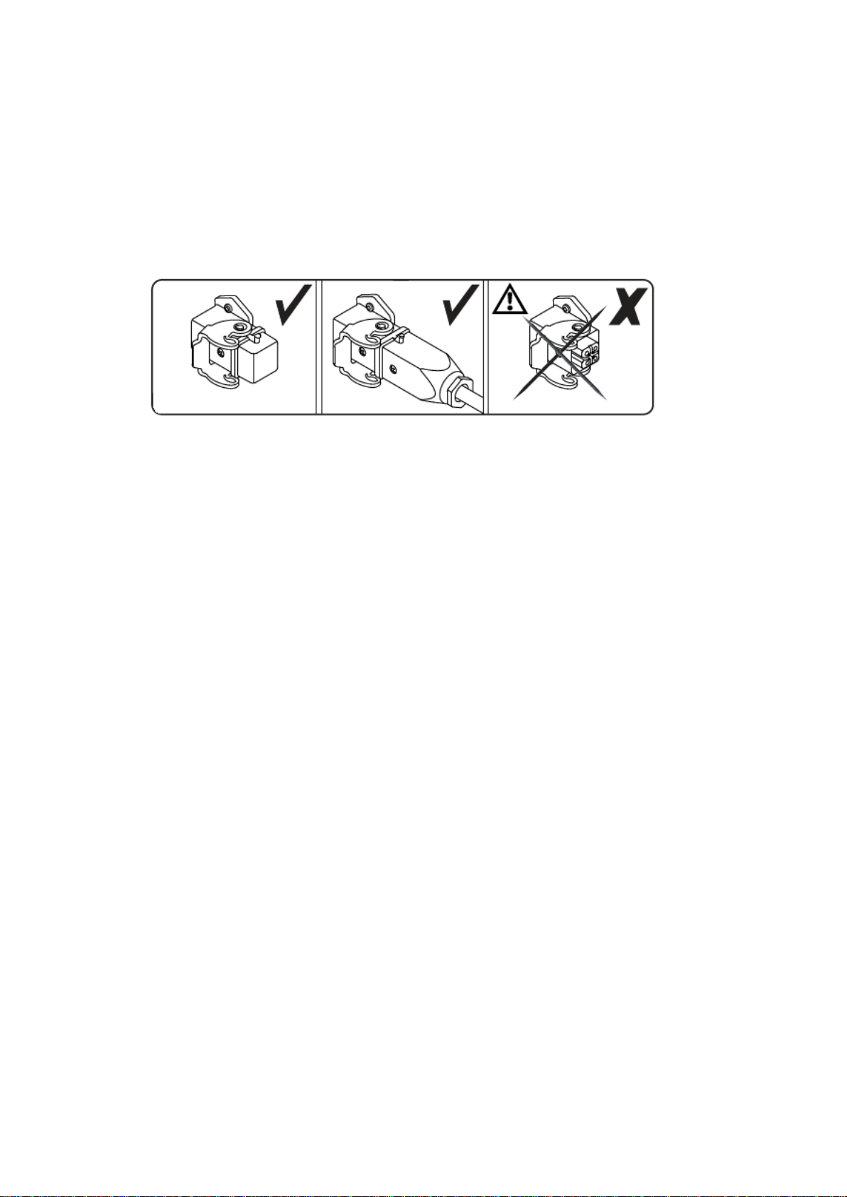
up is finished, the device may be disconnected from the mains!
Malfunction:
In case of an empty tank, abnormal combustion, dirty photocell, overheating or other defects, the control unit
detects a problem, interrupts the operating process, and indicates a fault caused by permanent red light of
the indicator light. This also serves as a reset button for acknowledging the fault, which is retained even after
the mains voltage has been switched off.
First determine and eliminate the cause of the fault before you disturb the control (by pressing the remaining
button for about 2 seconds).
10. Maintenance
Depending on the conditions of use and frequency of use, the maintenance intervals can be very different.
However, the device should be cleaned at least once a year and tested for function and safety. Maintenance
and repair work should only be carried out by persons with the necessary expertise.
Clean the fan wheel, the burner, the storage disc, the electrodes and the fuel filters in the tank filler neck,
filter housing, fuel pump and nozzle.
Replace defective or worn parts with original spare parts immediately. When ordering spare parts, always
specify the device type and serial number.
During cleaning work, always disconnect the device from the mains and work only on the cooled device.
Note that the device does not burn correctly when the burner cover is open because of the lower amount of
air.
Check the fuel tank and the filter housing A (Fig. 3) for contamination and condensation, and empty and
clean if necessary. Clean the filter insert B with appropriate means or replace it. Check the condition and
correct fit of the seals and replace them if necessary. A repair kit is available for this purpose (spare parts
list).
Check - and correct, if necessary - the adjustment of the air volume (Fig. 4), the oil pressure and the
electrodes (Fig. 5 + 6), and pay attention to the installation of a burner nozzle of the correct type, size and
spray angle. The correct values can be found in the drawings, spare parts lists and technical data.
Page 7 of 15

Operating- and Installation Manual B 380 - Hans Wilms GmbH & Co. KG
11. Storage and Transport
Note: Before any change of location, the device must be switched off and cool down sufficiently. Unplug it
from the outlet, make sure that the fuel cap and drain plug are tightly closed, and transport the device
straight.
When unloading, loading and transporting with forklifts, use forks that completely drive under the pallet.
Severe personal injury or property damage caused by crashing loads. Observe the safety regulations of the
conveyor vehicles and means of transport. Do not stop under floating loads!
If possible, store the device with an emptied and cleaned tank, and dustproof, but not airtight (condensation
moisture) packed in a dry and safe place.
Page 8 of 15
Fig.3
Fig. 4
Fig. 5
Fig. 6

Operating- and Installation Manual B 380 - Hans Wilms GmbH & Co. KG
12. Environmental Protection and Recycling
The heater is made exclusively from high-quality materials, most of which are recyclable.
Dispose of packaging material
Dispose of the packaging material in accordance with the locally applicable
environmental regulations.
Disposal of waste electrical and electronic equipment (WEEE)
For customers in EU countries
This device is subject to the European Directive 2012/19/EC on Waste Electrical and Electronic Equipment
(WEEE) and the corresponding national laws. The WEEE directive provides the framework for an EU-wide
treatment of waste electrical equipment.
The device is marked with the symbol of a crossed-out waste bin. This means that you must
not dispose of it with normal household waste, but rather dispose of it in an environmentally
friendly manner in a separate collection.
This device is intended as a professional electrical tool for exclusively commercial use (so-called B2B device
according to the WEEE Directive). In contrast to devices predominantly used in private households (so-called
B2C devices), this device may therefore not be handed over to the collection points of the public waste
disposal providers (e.g. municipal recycling centres) in some EU countries, e.g. in Germany. In case of doubt,
please inform yourself at your point of sale about the prescribed disposal route for B2B electrical appliances
in your country and ensure disposal in accordance with the applicable legal regulations. Please also note
any information on this in the purchase contract or in the general terms and conditions of your point of sale.
Proper disposal of this device avoids negative effects on people and the environment, serves the targeted
treatment of pollutants and enables the reuse of valuable raw materials.
Note: The electronic components are subject to special regulations for disposal.
Help protect the environment by ensuring that your old device is only disposed off in an
environmental-acceptable way!
13. Possible Faults and Solving
Fault
Cause
Remedy
Device plugged-in, power button
on "I", device does not start
No mains voltage available
Check socket/extension/cable
drum
When using a room thermostat,
the temperature in the room is
higher than the set temperature
Setting room thermostat to higher
temperature
Power supply or power button
defective
Check by customer service
Bridge plug of the thermostat
socket not plugged in
Attaching the bridge plug
Control indicates fault
Determine and eliminate the
cause, suppress control
Page 9 of 15

Operating- and Installation Manual B 380 - Hans Wilms GmbH & Co. KG
Fault
Cause
Remedy
Device starts, flame is formed,
control goes to fault after a few
seconds
Flame too dark, irregular or poor
combustion
Check the setting, check the filter
and nozzle for dirt
Photocell dirty, flame is not
detected
Clean photocell
Device starts, no flame formation,
control goes after a few seconds
on fault
Tank empty
Check tank level, refuel
Unclean, restless combustion,
smoke formation
Filter/nozzle dirty
Clean or replace the filter and
nozzle
Unsuitable or polluted fuel
Check the tank, empty and clean,
fill with clean heating oil EL
Device goes on fault after a long
runtime
Filters, oil pipes or tank ventilation
clogged
Check and clean
Lack of oxygen due to lack of
ventilation
Ensure sufficient ventilation, check
room size
Overheating of the device
Keep supply and exhaust air paths
clear, check fan and grille for
contamination, as well as setting
oil pressure / air volume and
nozzle size
Please note that maintenance and repair work may only be carried out by experts with appropriate
expertise. If in doubt, contact your dealer, your customer service center or the manufacturer!
Technical specifications are subject to changes without prior notice!
14. Technical Data
Type: B 380
Order number: 1081380
Capacity: 111,0 kW / 95460 kcal/h / 379.000 BTU/h
Air volume: 3300 m³/h
Fuel consumption: 8,83 kg/h
Burner nozzle: 2,0 GpH 80°H Danfoss
Pump pressure: 13 bar
Voltage: 230 V / 50 Hz
Power consumption: 4,6 A
Rated current: 1,06 kW
Weight: 82 kg
Tank capacity: 105 l
Dimensions: 1605 x 685 x 930 mm
Diameter air outlet: 400 mm
Protection class: IP 44
Page 10 of 15

Operating- and Installation Manual B 380 - Hans Wilms GmbH & Co. KG
15. Spare Parts List B 380
Pos. Order-No. D E S C R I P T I O N Qty.
2 6163601 Combustion chamber 1
3 6163602 Air regulation 1
4 6163603 Cage nut 1
5 6163604 Spacer 1
6 6163605 Safety thermostat 1
7 6163606 Photocell 1
8 6163607 Burner head 1
9 6163608 Nozzle 1
10 1138060 Screw M6x18 1
11 6163610 Burner head diffuser 1
12 6163615 Twin electrode 1
13 5940331 Screw M5x16 1
14 6163617 Spring ring 5 mm 1
15 6163618 Disk 1
16 6163619 Cable gland 1
17 6163620 Outlet cone 1
18 6163625 Cover 1
19 6163626 Air deflector 2
20 6163628 Upper shell 1
21 6163629 Grommet 2
22 6163630 Lower shell 1
23 6163631 Double nipple 2
24 6163632 Filter with oil preheater 1
25 6163636 Fuel pipe tank filter 1
26 6163637 Holder filter 1
27 6163638 Lateral panel –right 1
28 6163639 Air deflector 1
29 6163640 Front panel 1
30 6163641 Fuel gauge 1
31 6163642 Lateral control panel –left 1
32 6163643 Breath valve 1
33 6163644 Clip 2
34 1139254 Nut 2
35 6160593 Strain relief bushing 2
36 6163645 Rubber pipe 1
38 6163646 90° Air connection 1
39 6163647 Straight connection 1
40 6163648 Suction pipe 1
41 6163649 Rear panel 1
42 6163650 Power cord bracket 1
43 6163655 Fan wheel 1
44 6163656 Motor support 1
45 6163657 Motor 1
Use only original parts from the manufacturer for repair!
Page 11 of 15

Operating- and Installation Manual B 380 - Hans Wilms GmbH & Co. KG
Exploded View B 380
Page 12 of 15

Operating- and Installation Manual B 380 - Hans Wilms GmbH & Co. KG
15. Spare Parts List B 380 Page 2
Pos. Order-No. D E S C R I P T I O N Qty.
46 3308072 Coupling 1
47 6163658 Fuel pump 1
48 6160591 Reduction sleeve 1
49 6163659 90° Fuel connection 2
50 6163660 Fuel flexible pipe 1
51 6163661 Grille 1
52 6163662 Fuel pipe pump filter 1
53 6163663 Fuel pipe pump tank 1
54 6163664 Pump valve power cord 1
55 6163655 Handle 1
56 6163666 Handle cap 2
57 6163667 Tank cap 1
58 6163668 Tank filter 1
59 6163669 Tank 1
60 6163670 Tank drain cap 1
61 6163675 Chassis 1
62 6163676 Axle 1
63 6163677 Wheel 2
64 6163678 Block washer 4
65 6163679 Wheel cap 2
66 6160452 Cable bushing 4
67 6163680 Housing 1
68 6163681 Ignition cable 2
69 6160464 Plug distributor earth 1
70 6163682 Fuse F10A 2
71 6163683 Fuse holder 1
72 6163684 Transformer 1
73 6163685 Control panel base 1
74 6163686 Cord 1
75 6163687 Relay 1
76 6163688 Power cord 1
77 6163689 Control box 1
78 6163635 Filter insert 1
79 6163633 Gasket kit filter 1
80 6160160 Jumper 1
81 6160532 Plug insert 1
82 6160533 Jack housing 1
83 6163690 Switch 1
84 6163691 Cap 1
85 6163692 Sticker 1
86 6163693 Control panel 1
not illustrated 6163694 Screw (Housing) 30
Use only original parts from the manufacturer for repair!
Page 13 of 15

Operating- and Installation Manual B 380 - Hans Wilms GmbH & Co. KG
Exploded View B 380
Page 14 of 15

Operating- and Installation Manual B 380 - Hans Wilms GmbH & Co. KG
17. Wiring Diagram
Pos.
Order-No.
Description
Qty.
FO
6163606
Photocell
1
TA
6160160
Jumper (or room thermostat - optional, see accessories list)
1
IG
6163684
Ignition transformer
1
FPH
6163632
Filter with oil preheater
1
M
6163657
Motor
1
R
6163687
Relay
1
IN
6163690
Switch
1
FU
6163682
Fuse F10A
1
EV
6162701
Solenoid valve complete
1
TS
6163605
Safety thermostat
Safety thermostat
Safety thermostat
1
Page 15 of 15
This manual suits for next models
1
Table of contents
Other WILMS Heater manuals
Popular Heater manuals by other brands

VOLTOMAT HEATING
VOLTOMAT HEATING CH-111017.1 instruction manual

Certikin
Certikin MB055 Operating, installation and servicing instructions

RADSON
RADSON MENAI E - MOUNTING Instruction

Snugger
Snugger SF2300 user manual

Chromalox
Chromalox V-2020 Installation and rewnewal parts identification

Thermoheat
Thermoheat LPFA125/L User's manual and operating instructions